(27.8)
m = d sin θ
λ .
Taking sin θ = 1 and substituting the values of d and λ from the preceding example gives
(27.9)
m = (0.0100 mm)(1)
633 nm
≈ 15.8.
Therefore, the largest integer m can be is 15, or
m
(27.10)
= 15.
Discussion
The number of fringes depends on the wavelength and slit separation. The number of fringes will be very large for large slit separations.
However, if the slit separation becomes much greater than the wavelength, the intensity of the interference pattern changes so that the screen
has two bright lines cast by the slits, as expected when light behaves like a ray. We also note that the fringes get fainter further away from the
center. Consequently, not all 15 fringes may be observable.
27.4 Multiple Slit Diffraction
An interesting thing happens if you pass light through a large number of evenly spaced parallel slits, called a diffraction grating. An interference
pattern is created that is very similar to the one formed by a double slit (see Figure 27.16). A diffraction grating can be manufactured by scratching glass with a sharp tool in a number of precisely positioned parallel lines, with the untouched regions acting like slits. These can be photographically
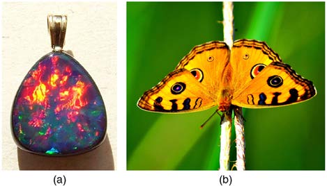
mass produced rather cheaply. Diffraction gratings work both for transmission of light, as in Figure 27.16, and for reflection of light, as on butterfly
wings and the Australian opal in Figure 27.17 or the CD pictured in the opening photograph of this chapter, Figure 27.1. In addition to their use as
novelty items, diffraction gratings are commonly used for spectroscopic dispersion and analysis of light. What makes them particularly useful is the
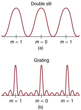
fact that they form a sharper pattern than double slits do. That is, their bright regions are narrower and brighter, while their dark regions are darker.
Figure 27.18 shows idealized graphs demonstrating the sharper pattern. Natural diffraction gratings occur in the feathers of certain birds. Tiny, finger-like structures in regular patterns act as reflection gratings, producing constructive interference that gives the feathers colors not solely due to their
pigmentation. This is called iridescence.
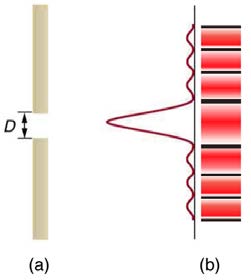
Figure 27.16 A diffraction grating is a large number of evenly spaced parallel slits. (a) Light passing through is diffracted in a pattern similar to a double slit, with bright regions at various angles. (b) The pattern obtained for white light incident on a grating. The central maximum is white, and the higher-order maxima disperse white light into a rainbow
of colors.
966 CHAPTER 27 | WAVE OPTICS
Figure 27.17 (a) This Australian opal and (b) the butterfly wings have rows of reflectors that act like reflection gratings, reflecting different colors at different angles. (credits: (a) Opals-On-Black.com, via Flickr (b) whologwhy, Flickr)
Figure 27.18 Idealized graphs of the intensity of light passing through a double slit (a) and a diffraction grating (b) for monochromatic light. Maxima can be produced at the
same angles, but those for the diffraction grating are narrower and hence sharper. The maxima become narrower and the regions between darker as the number of slits is
increased.
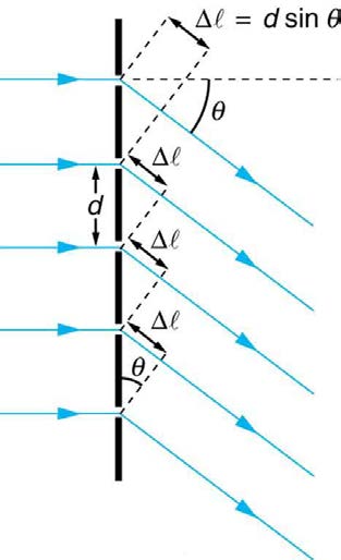
The analysis of a diffraction grating is very similar to that for a double slit (see Figure 27.19). As we know from our discussion of double slits in
Young's Double Slit Experiment, light is diffracted by each slit and spreads out after passing through. Rays traveling in the same direction (at an angle θ relative to the incident direction) are shown in the figure. Each of these rays travels a different distance to a common point on a screen far
away. The rays start in phase, and they can be in or out of phase when they reach a screen, depending on the difference in the path lengths traveled.
As seen in the figure, each ray travels a distance d sin θ different from that of its neighbor, where d is the distance between slits. If this distance
equals an integral number of wavelengths, the rays all arrive in phase, and constructive interference (a maximum) is obtained. Thus, the condition
necessary to obtain constructive interference for a diffraction grating is
d
(27.11)
sin θ = mλ, for m = 0, 1, –1, 2, –2, … (constructive),
where d is the distance between slits in the grating, λ is the wavelength of light, and m is the order of the maximum. Note that this is exactly the
same equation as for double slits separated by d . However, the slits are usually closer in diffraction gratings than in double slits, producing fewer
maxima at larger angles.
CHAPTER 27 | WAVE OPTICS 967
Figure 27.19 Diffraction grating showing light rays from each slit traveling in the same direction. Each ray travels a different distance to reach a common point on a screen (not shown). Each ray travels a distance d sin θ different from that of its neighbor.
Where are diffraction gratings used? Diffraction gratings are key components of monochromators used, for example, in optical imaging of particular
wavelengths from biological or medical samples. A diffraction grating can be chosen to specifically analyze a wavelength emitted by molecules in
diseased cells in a biopsy sample or to help excite strategic molecules in the sample with a selected frequency of light. Another vital use is in optical
fiber technologies where fibers are designed to provide optimum performance at specific wavelengths. A range of diffraction gratings are available for
selecting specific wavelengths for such use.
Take-Home Experiment: Rainbows on a CD
The spacing d of the grooves in a CD or DVD can be well determined by using a laser and the equation
d sin θ = mλ, for m = 0, 1, –1, 2, –2, … . However, we can still make a good estimate of this spacing by using white light and the
rainbow of colors that comes from the interference. Reflect sunlight from a CD onto a wall and use your best judgment of the location of a
strongly diffracted color to find the separation d .
Example 27.3 Calculating Typical Diffraction Grating Effects
Diffraction gratings with 10,000 lines per centimeter are readily available. Suppose you have one, and you send a beam of white light through it
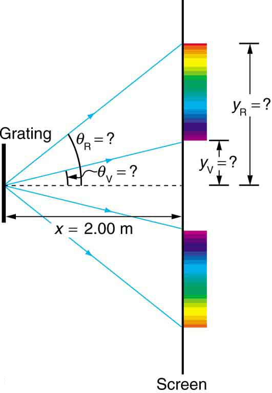
to a screen 2.00 m away. (a) Find the angles for the first-order diffraction of the shortest and longest wavelengths of visible light (380 and 760
nm). (b) What is the distance between the ends of the rainbow of visible light produced on the screen for first-order interference? (See Figure
968 CHAPTER 27 | WAVE OPTICS
Figure 27.20 The diffraction grating considered in this example produces a rainbow of colors on a screen a distance x = 2.00 m from the grating. The distances
along the screen are measured perpendicular to the x -direction. In other words, the rainbow pattern extends out of the page.
Strategy
The angles can be found using the equation
d
(27.12)
sin θ = mλ (for m = 0, 1, –1, 2, –2, …)
once a value for the slit spacing d has been determined. Since there are 10,000 lines per centimeter, each line is separated by 1/10,000 of a
centimeter. Once the angles are found, the distances along the screen can be found using simple trigonometry.
Solution for (a)
The distance between slits is d = (1 cm) / 10 , 000 = 1.00×10⁻⁴ cm or 1.00×10⁻⁶ m . Let us call the two angles θ V for violet (380 nm)
and θ R for red (760 nm). Solving the equation d sin θ V = mλ for sin θ V ,
(27.13)
sin θ V = mλ V
d ,
where m = 1 for first order and λ V = 380 nm = 3.80×10⁻⁷ m . Substituting these values gives
(27.14)
sin θ V = 3.80×10⁻⁷ m = 0.380.
1.00×10⁻⁶ m
Thus the angle θ V is
(27.15)
θ V = sin−1 0.380 = 22.33º.
Similarly,
(27.16)
sin θ R = 7.60×10⁻⁷ m.
1.00×10⁻⁶ m
Thus the angle θ R is
(27.17)
θ R = sin−1 0.760 = 49.46º.
Notice that in both equations, we reported the results of these intermediate calculations to four significant figures to use with the calculation in
part (b).
Solution for (b)
The distances on the screen are labeled y V and y R in Figure 27.20. Noting that tan θ = y / x , we can solve for y V and y R . That is, y
(27.18)
V = x tan θ V = (2.00 m)(tan 22.33º) = 0.815 m
CHAPTER 27 | WAVE OPTICS 969
and
y
(27.19)
R = x tan θ R = (2.00 m)(tan 49.46º) = 2.338 m.
The distance between them is therefore
y
(27.20)
R − y V = 1.52 m.
Discussion
The large distance between the red and violet ends of the rainbow produced from the white light indicates the potential this diffraction grating has
as a spectroscopic tool. The more it can spread out the wavelengths (greater dispersion), the more detail can be seen in a spectrum. This
depends on the quality of the diffraction grating—it must be very precisely made in addition to having closely spaced lines.
27.5 Single Slit Diffraction
Light passing through a single slit forms a diffraction pattern somewhat different from those formed by double slits or diffraction gratings. Figure 27.21
shows a single slit diffraction pattern. Note that the central maximum is larger than those on either side, and that the intensity decreases rapidly on
either side. In contrast, a diffraction grating produces evenly spaced lines that dim slowly on either side of center.
Figure 27.21 (a) Single slit diffraction pattern. Monochromatic light passing through a single slit has a central maximum and many smaller and dimmer maxima on either side.
The central maximum is six times higher than shown. (b) The drawing shows the bright central maximum and dimmer and thinner maxima on either side.
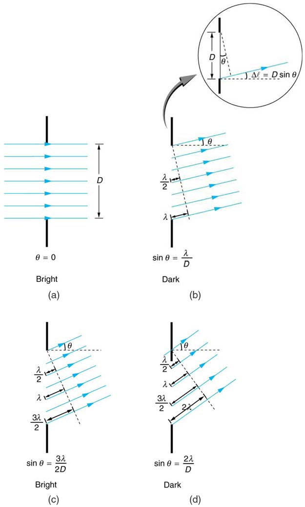
The analysis of single slit diffraction is illustrated in Figure 27.22. Here we consider light coming from different parts of the same slit. According to Huygens’s principle, every part of the wavefront in the slit emits wavelets. These are like rays that start out in phase and head in all directions. (Each
ray is perpendicular to the wavefront of a wavelet.) Assuming the screen is very far away compared with the size of the slit, rays heading toward a
common destination are nearly parallel. When they travel straight ahead, as in Figure 27.22(a), they remain in phase, and a central maximum is
obtained. However, when rays travel at an angle θ relative to the original direction of the beam, each travels a different distance to a common
location, and they can arrive in or out of phase. In Figure 27.22(b), the ray from the bottom travels a distance of one wavelength λ farther than the ray from the top. Thus a ray from the center travels a distance λ / 2 farther than the one on the left, arrives out of phase, and interferes destructively.
A ray from slightly above the center and one from slightly above the bottom will also cancel one another. In fact, each ray from the slit will have
another to interfere destructively, and a minimum in intensity will occur at this angle. There will be another minimum at the same angle to the right of
the incident direction of the light.
970 CHAPTER 27 | WAVE OPTICS
Figure 27.22 Light passing through a single slit is diffracted in all directions and may interfere constructively or destructively, depending on the angle. The difference in path length for rays from either side of the slit is seen to be D sin θ .
At the larger angle shown in Figure 27.22(c), the path lengths differ by 3λ / 2 for rays from the top and bottom of the slit. One ray travels a distance λ different from the ray from the bottom and arrives in phase, interfering constructively. Two rays, each from slightly above those two, will also add
constructively. Most rays from the slit will have another to interfere with constructively, and a maximum in intensity will occur at this angle. However,
all rays do not interfere constructively for this situation, and so the maximum is not as intense as the central maximum. Finally, in Figure 27.22(d), the angle shown is large enough to produce a second minimum. As seen in the figure, the difference in path length for rays from either side of the slit is
D sin θ , and we see that a destructive minimum is obtained when this distance is an integral multiple of the wavelength.
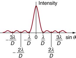
Figure 27.23 A graph of single slit diffraction intensity showing the central maximum to be wider and much more intense than those to the sides. In fact the central maximum is
six times higher than shown here.
CHAPTER 27 | WAVE OPTICS 971
Thus, to obtain destructive interference for a single slit,
D
(27.21)
sin θ = mλ, for m = 1, –1, 2, –2, 3, … (destructive),
where D is the slit width, λ is the light’s wavelength, θ is the angle relative to the original direction of the light, and m is the order of the minimum.
Figure 27.23 shows a graph of intensity for single slit interference, and it is apparent that the maxima on either side of the central maximum are much less intense and not as wide. This is consistent with the illustration in Figure 27.21(b).
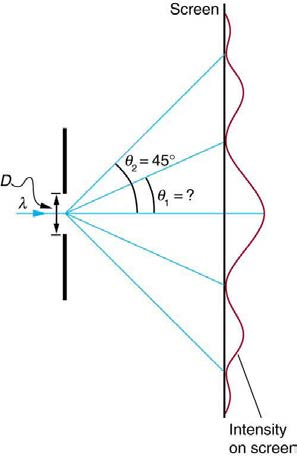
Example 27.4 Calculating Single Slit Diffraction
Visible light of wavelength 550 nm falls on a single slit and produces its second diffraction minimum at an angle of 45.0º relative to the incident
direction of the light. (a) What is the width of the slit? (b) At what angle is the first minimum produced?
Figure 27.24 A graph of the single slit diffraction pattern is analyzed in this example.
Strategy
From the given information, and assuming the screen is far away from the slit, we can use the equation D sin θ = mλ first to find D , and
again to find the angle for the first minimum θ 1 .
Solution for (a)
We are given that λ = 550 nm , m = 2 , and θ 2 = 45.0º . Solving the equation D sin θ = mλ for D and substituting known values gives (27.22)
D =
mλ
sin θ = 2(550 nm)
2
sin 45.0º
= 1100×10−9
0.707
= 1.56×10⁻⁶.
Solution for (b)
Solving the equation D sin θ = mλ for sin θ 1 and substituting the known values gives
(27.23)
1⎛
sin θ
⎝550×10−9 m⎞⎠
1 = mλ
D =
.
1.56×10⁻⁶ m
Thus the angle θ 1 is
(27.24)
θ 1 = sin−1 0.354 = 20.7º.
Discussion
We see that the slit is narrow (it is only a few times greater than the wavelength of light). This is consistent with the fact that light must interact
with an object comparable in size to its wavelength in order to exhibit significant wave effects such as this single slit diffraction pattern. We also
see that the central maximum extends 20.7º on either side of the original beam, for a width of about 41º . The angle between the first and
second minima is only about 24º (45.0º − 20.7º) . Thus the second maximum is only about half as wide as the central maximum.
972 CHAPTER 27 | WAVE OPTICS
27.6 Limits of Resolution: The Rayleigh Criterion
Light diffracts as it moves through space, bending around obstacles, interfering constructively and destructively. While this can be used as a
spectroscopic tool—a diffraction grating disperses light according to wavelength, for example, and is used to produce spectra—diffraction also limits
the detail we can obtain in images. Figure 27.25(a) shows the effect of passing light through a small circular aperture. Instead of a bright spot with sharp edges, a spot with a fuzzy edge surrounded by circles of light is obtained. This pattern is caused by diffraction similar to that produced by a
single slit. Light from different parts of the circular aperture interferes constructively and destructively. The effect is most noticeable when the aperture
is small, but the effect is there for large apertures, too.
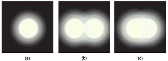
Figure 27.25 (a) Monochromatic light passed through a small circular aperture produces this diffraction pattern. (b) Two point light sources that are close to one another
produce overlapping images because of diffraction. (c) If they are closer together, they cannot be resolved or distinguished.
How does diffraction affect the detail that can be observed when light passes through an aperture? Figure 27.25(b) shows the diffraction pattern
produced by two point light sources that are close to one another. The pattern is similar to that for a single point source, and it is just barely possible
to tell that there are two light sources rather than one. If they were closer together, as in Figure 27.25(c), we could not distinguish them, thus limiting
the detail or resolution we can obtain. This limit is an inescapable consequence of the wave nature of light.
There are many situations in which diffraction limits the resolution. The acuity of our vision is limited because light passes through the pupil, the
circular aperture of our eye. Be aware that the diffraction-like spreading of light is due to the limited diameter of a light beam, not the interaction with
an aperture. Thus light passing through a lens with a diameter D shows this effect and spreads, blurring the image, just as light passing through an
aperture of diameter D does. So diffraction limits the resolution of any system having a lens or mirror. Telescopes are also limited by diffraction,
because of the finite diameter D of their primary mirror.
Take-Home Experiment: Resolution of the Eye
Draw two lines on a white sheet of paper (several mm apart). How far away can you be and still distinguish the two lines? What does this tell you
about the size of the eye’s pupil? Can you be quantitative? (The size of an adult’s pupil is discussed in Physics of the Eye.)
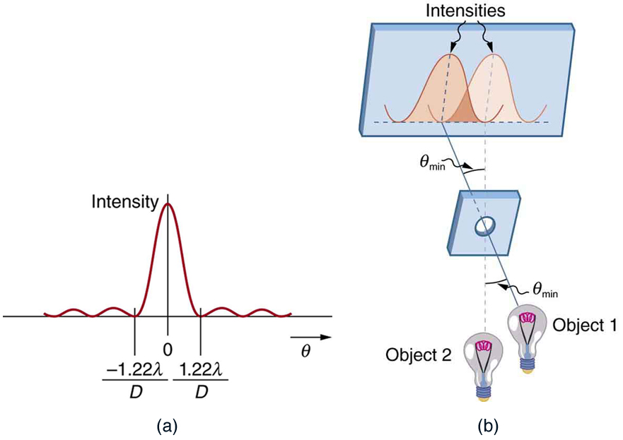
Just what is the limit? To answer that question, consider the diffraction pattern for a circular aperture, which has a central maximum that is wider and
brighter than the maxima surrounding it (similar to a slit) [see Figure 27.26(a)]. It can be shown that, for a circular aperture of diameter D , the first minimum in the diffraction pattern occurs at θ = 1.22 λ / D (providing the aperture is large compared with the wavelength of light, which is the case
for most optical instruments). The accepted criterion for determining the diffraction limit to resolution based on this angle was developed by Lord
Rayleigh in the 19th century. The Rayleigh criterion for the diffraction limit to resolution states that two images are just resolvable when the center of
the diffraction pattern of one is directly over the first minimum of the diffraction pattern of the other. See Figure 27.26(b). The first minimum is at an
angle of θ = 1.22 λ / D , so that two point objects are just resolvable if they are separated by the angle
(27.25)
θ = 1.22 λD,
where λ is the wavelength of light (or other electromagnetic radiation) and D is the diameter of the aperture, lens, mirror, etc., with which the two
objects are observed. In this expression, θ has units of radians.
CHAPTER 27 | WAVE OPTICS 973
Figure 27.26 (a) Graph of intensity of the diffraction pattern for a circular aperture. Note that, similar to a single slit, the central maximum is wider and brighter than those to the sides. (b) Two point objects produce overlapping diffraction patterns. Shown here is the Rayleigh criterion for being just resolvable. The central maximum of one pattern lies on
the first minimum of the other.
Connections: Limits to Knowledge
All attempts to observe the size and shape of objects are limited by the wavelength of the probe. Even the small wavelength of light prohibits
exact precision. When extremely small wavelength probes as with an electron microscope are used, the system is disturbed, still limiting our
knowledge, much as making an electrical measurement alters a circuit. Heisenberg’s uncertainty principle asserts that this limit is fundamental
and inescapable, as we shall see in quantum mechanics.
Example 27.5 Calculating Diffraction Limits of the Hubble Space Telescope
The primary mirror of the orbiting Hubble Space Telescope has a diameter of 2.40 m. Being in orbit, this telescope avoids the degrading effects
of atmospheric distortion on its resolution. (a) What is the angle between two just-resolvable point light sources (perhaps two stars)? Assume an
average light wavelength of 550 nm. (b) If these two stars are at the 2 million light year distance of the Andromeda galaxy, how close together
can they be and still be resolved? (A light year, or ly, is the distance light travels in 1 year.)
Strategy
The Rayleigh criterion stated in the equation θ = 1.22 λ
D gives the smallest possible angle θ between point sources, or the best obtainable
resolution. Once this angle is found, the distance between stars can be calculated, since we are given how far away they are.
Solution for (a)
The Rayleigh criterion for the minimum resolvable angle is
(27.26)
θ = 1.22 λD. <
Describe what you're looking for in as much detail as you'd like.
Our AI reads your request and finds the best matching books for you.
Popular searches:
Join 2.9 million readers and get unlimited free ebooks