jobs that use thin film interference to produce colors that change with angle. This expensive option is based on variation of thin film path length
differences with angle. Security features on credit cards, banknotes, driving licenses and similar items prone to forgery use thin film interference,
diffraction gratings, or holograms. Australia led the way with dollar bills printed on polymer with a diffraction grating security feature making the
currency difficult to forge. Other countries such as New Zealand and Taiwan are using similar technologies, while the United States currency includes
a thin film interference effect.
Making Connections: Take-Home Experiment—Thin Film Interference
One feature of thin film interference and diffraction gratings is that the pattern shifts as you change the angle at which you look or move your
head. Find examples of thin film interference and gratings around you. Explain how the patterns change for each specific example. Find
examples where the thickness changes giving rise to changing colors. If you can find two microscope slides, then try observing the effect shown
in Figure 27.34. Try separating one end of the two slides with a hair or maybe a thin piece of paper and observe the effect.
Problem-Solving Strategies for Wave Optics
Step 1. Examine the situation to determine that interference is involved. Identify whether slits or thin film interference are considered in the problem.
Step 2. If slits are involved, note that diffraction gratings and double slits produce very similar interference patterns, but that gratings have narrower
(sharper) maxima. Single slit patterns are characterized by a large central maximum and smaller maxima to the sides.
Step 3. If thin film interference is involved, take note of the path length difference between the two rays that interfere. Be certain to use the
wavelength in the medium involved, since it differs from the wavelength in vacuum. Note also that there is an additional λ / 2 phase shift when light
reflects from a medium with a greater index of refraction.
Step 4. Identify exactly what needs to be determined in the problem (identify the unknowns). A written list is useful. Draw a diagram of the situation.
Labeling the diagram is useful.
Step 5. Make a list of what is given or can be inferred from the problem as stated (identify the knowns).
980 CHAPTER 27 | WAVE OPTICS
Step 6. Solve the appropriate equation for the quantity to be determined (the unknown), and enter the knowns. Slits, gratings, and the Rayleigh limit
involve equations.
Step 7. For thin film interference, you will have constructive interference for a total shift that is an integral number of wavelengths. You will have
destructive interference for a total shift of a half-integral number of wavelengths. Always keep in mind that crest to crest is constructive whereas crest
to trough is destructive.
Step 8. Check to see if the answer is reasonable: Does it make sense? Angles in interference patterns cannot be greater than 90º , for example.
27.8 Polarization
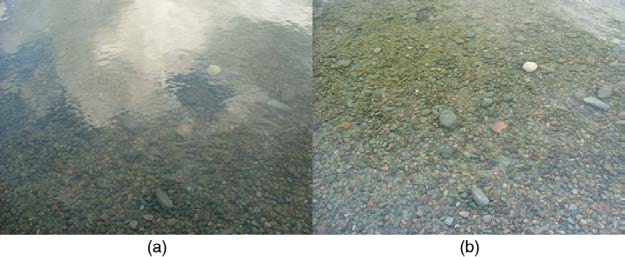
Polaroid sunglasses are familiar to most of us. They have a special ability to cut the glare of light reflected from water or glass (see Figure 27.36).
Polaroids have this ability because of a wave characteristic of light called polarization. What is polarization? How is it produced? What are some of its
uses? The answers to these questions are related to the wave character of light.
Figure 27.36 These two photographs of a river show the effect of a polarizing filter in reducing glare in light reflected from the surface of water. Part (b) of this figure was taken with a polarizing filter and part (a) was not. As a result, the reflection of clouds and sky observed in part (a) is not observed in part (b). Polarizing sunglasses are particularly
useful on snow and water. (credit: Amithshs, Wikimedia Commons)
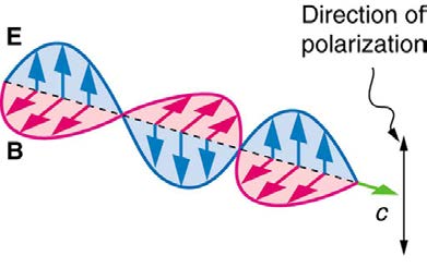
Light is one type of electromagnetic (EM) wave. As noted earlier, EM waves are transverse waves consisting of varying electric and magnetic fields
that oscillate perpendicular to the direction of propagation (see Figure 27.37). There are specific directions for the oscillations of the electric and
magnetic fields. Polarization is the attribute that a wave’s oscillations have a definite direction relative to the direction of propagation of the wave.
(This is not the same type of polarization as that discussed for the separation of charges.) Waves having such a direction are said to be polarized.
For an EM wave, we define the direction of polarization to be the direction parallel to the electric field. Thus we can think of the electric field arrows
as showing the direction of polarization, as in Figure 27.37.
Figure 27.37 An EM wave, such as light, is a transverse wave. The electric and magnetic fields are perpendicular to the direction of propagation.
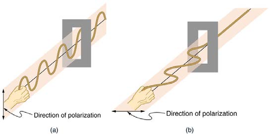
To examine this further, consider the transverse waves in the ropes shown in Figure 27.38. The oscillations in one rope are in a vertical plane and are said to be vertically polarized. Those in the other rope are in a horizontal plane and are horizontally polarized. If a vertical slit is placed on the
first rope, the waves pass through. However, a vertical slit blocks the horizontally polarized waves. For EM waves, the direction of the electric field is
analogous to the disturbances on the ropes.
Figure 27.38 The transverse oscillations in one rope are in a vertical plane, and those in the other rope are in a horizontal plane. The first is said to be vertically polarized, and the other is said to be horizontally polarized. Vertical slits pass vertically polarized waves and block horizontally polarized waves.
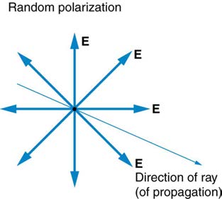
The Sun and many other light sources produce waves that are randomly polarized (see Figure 27.39). Such light is said to be unpolarized because it is composed of many waves with all possible directions of polarization. Polaroid materials, invented by the founder of Polaroid Corporation, Edwin

CHAPTER 27 | WAVE OPTICS 981
Land, act as a polarizing slit for light, allowing only polarization in one direction to pass through. Polarizing filters are composed of long molecules
aligned in one direction. Thinking of the molecules as many slits, analogous to those for the oscillating ropes, we can understand why only light with a
specific polarization can get through. The axis of a polarizing filter is the direction along which the filter passes the electric field of an EM wave (see
Figure 27.39 The slender arrow represents a ray of unpolarized light. The bold arrows represent the direction of polarization of the individual waves composing the ray. Since
the light is unpolarized, the arrows point in all directions.
Figure 27.40 A polarizing filter has a polarization axis that acts as a slit passing through electric fields parallel to its direction. The direction of polarization of an EM wave is defined to be the direction of its electric field.
Figure 27.41 shows the effect of two polarizing filters on originally unpolarized light. The first filter polarizes the light along its axis. When the axes of the first and second filters are aligned (parallel), then all of the polarized light passed by the first filter is also passed by the second. If the second
polarizing filter is rotated, only the component of the light parallel to the second filter’s axis is passed. When the axes are perpendicular, no light is
passed by the second.
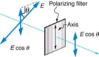
Only the component of the EM wave parallel to the axis of a filter is passed. Let us call the angle between the direction of polarization and the axis of
a filter θ . If the electric field has an amplitude E , then the transmitted part of the wave has an amplitude E cos θ (see Figure 27.42). Since the intensity of a wave is proportional to its amplitude squared, the intensity I of the transmitted wave is related to the incident wave by
(27.44)
I = I 0 cos2 θ,
where I 0 is the intensity of the polarized wave before passing through the filter. (The above equation is known as Malus’s law.)

982 CHAPTER 27 | WAVE OPTICS
Figure 27.41 The effect of rotating two polarizing filters, where the first polarizes the light. (a) All of the polarized light is passed by the second polarizing filter, because its axis is parallel to the first. (b) As the second is rotated, only part of the light is passed. (c) When the second is perpendicular to the first, no light is passed. (d) In this photograph, a polarizing filter is placed above two others. Its axis is perpendicular to the filter on the right (dark area) and parallel to the filter on the left (lighter area). (credit: P.P. Urone) Figure 27.42 A polarizing filter transmits only the component of the wave parallel to its axis, E cos θ , reducing the intensity of any light not polarized parallel to its axis.
Example 27.8 Calculating Intensity Reduction by a Polarizing Filter
What angle is needed between the direction of polarized light and the axis of a polarizing filter to reduce its intensity by 90.0% ?
Strategy
When the intensity is reduced by 90.0% , it is 10.0% or 0.100 times its original value. That is, I = 0.100 I 0 . Using this information, the
equation I = I 0 cos2 θ can be used to solve for the needed angle.
Solution
Solving the equation I = I 0 cos2 θ for cos θ and substituting with the relationship between I and I 0 gives
(27.45)
cos θ = II = 0.100 I 0 = 0.3162.
0
I 0
Solving for θ yields
(27.46)
θ = cos−1 0.3162 = 71.6º.
Discussion
A fairly large angle between the direction of polarization and the filter axis is needed to reduce the intensity to 10.0% of its original value. This
seems reasonable based on experimenting with polarizing films. It is interesting that, at an angle of 45º , the intensity is reduced to 50% of its
original value (as you will show in this section’s Problems & Exercises). Note that 71.6º is 18.4º from reducing the intensity to zero, and that at
an angle of 18.4º the intensity is reduced to 90.0% of its original value (as you will also show in Problems & Exercises), giving evidence of
symmetry.
Polarization by Reflection
By now you can probably guess that Polaroid sunglasses cut the glare in reflected light because that light is polarized. You can check this for yourself
by holding Polaroid sunglasses in front of you and rotating them while looking at light reflected from water or glass. As you rotate the sunglasses, you
CHAPTER 27 | WAVE OPTICS 983
will notice the light gets bright and dim, but not completely black. This implies the reflected light is partially polarized and cannot be completely
blocked by a polarizing filter.
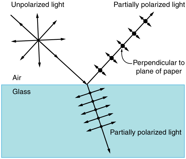
Figure 27.43 illustrates what happens when unpolarized light is reflected from a surface. Vertically polarized light is preferentially refracted at the surface, so that the reflected light is left more horizontally polarized. The reasons for this phenomenon are beyond the scope of this text, but a
convenient mnemonic for remembering this is to imagine the polarization direction to be like an arrow. Vertical polarization would be like an arrow
perpendicular to the surface and would be more likely to stick and not be reflected. Horizontal polarization is like an arrow bouncing on its side and
would be more likely to be reflected. Sunglasses with vertical axes would then block more reflected light than unpolarized light from other sources.
Figure 27.43 Polarization by reflection. Unpolarized light has equal amounts of vertical and horizontal polarization. After interaction with a surface, the vertical components are preferentially absorbed or refracted, leaving the reflected light more horizontally polarized. This is akin to arrows striking on their sides bouncing off, whereas arrows striking on
their tips go into the surface.
Since the part of the light that is not reflected is refracted, the amount of polarization depends on the indices of refraction of the media involved. It can
be shown that reflected light is completely polarized at a angle of reflection θ b , given by
(27.47)
tan θ b = n 2
n ,
1
where n 1 is the medium in which the incident and reflected light travel and n 2 is the index of refraction of the medium that forms the interface that
reflects the light. This equation is known as Brewster’s law, and θ b is known as Brewster’s angle, named after the 19th-century Scottish physicist
who discovered them.
Things Great and Small: Atomic Explanation of Polarizing Filters
Polarizing filters have a polarization axis that acts as a slit. This slit passes electromagnetic waves (often visible light) that have an electric field
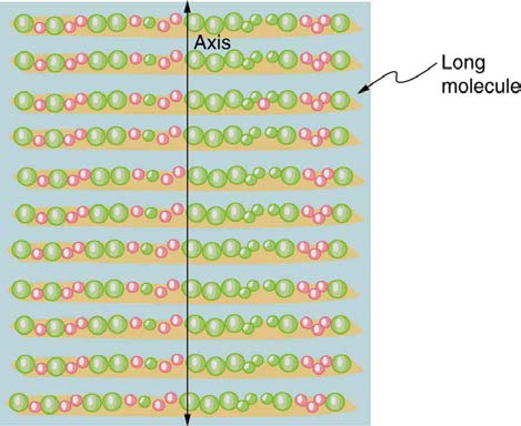
parallel to the axis. This is accomplished with long molecules aligned perpendicular to the axis as shown in Figure 27.44.
Figure 27.44 Long molecules are aligned perpendicular to the axis of a polarizing filter. The component of the electric field in an EM wave perpendicular to these
molecules passes through the filter, while the component parallel to the molecules is absorbed.
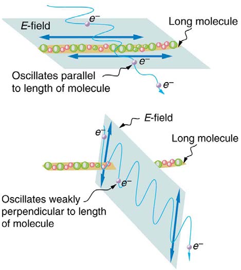
Figure 27.45 illustrates how the component of the electric field parallel to the long molecules is absorbed. An electromagnetic wave is composed
of oscillating electric and magnetic fields. The electric field is strong compared with the magnetic field and is more effective in exerting force on
charges in the molecules. The most affected charged particles are the electrons in the molecules, since electron masses are small. If the
electron is forced to oscillate, it can absorb energy from the EM wave. This reduces the fields in the wave and, hence, reduces its intensity. In
long molecules, electrons can more easily oscillate parallel to the molecule than in the perpendicular direction. The electrons are bound to the
984 CHAPTER 27 | WAVE OPTICS
molecule and are more restricted in their movement perpendicular to the molecule. Thus, the electrons can absorb EM waves that have a
component of their electric field parallel to the molecule. The electrons are much less responsive to electric fields perpendicular to the molecule
and will allow those fields to pass. Thus the axis of the polarizing filter is perpendicular to the length of the molecule.
Figure 27.45 Artist’s conception of an electron in a long molecule oscillating parallel to the molecule. The oscillation of the electron absorbs energy and reduces the
intensity of the component of the EM wave that is parallel to the molecule.
Example 27.9 Calculating Polarization by Reflection
(a) At what angle will light traveling in air be completely polarized horizontally when reflected from water? (b) From glass?
Strategy
All we need to solve these problems are the indices of refraction. Air has n 1 = 1.00, water has n 2 = 1.333, and crown glass has
n′2 = 1.520 . The equation tan θ b = n 2
n can be directly applied to find θ
1
b in each case.
Solution for (a)
Putting the known quantities into the equation
(27.48)
tan θ b = n 2
n 1
gives
(27.49)
tan θ b = n 2
n = 1.333
1
1.00 = 1.333.
Solving for the angle θ b yields
(27.50)
θ b = tan−1 1.333 = 53.1º.
Solution for (b)
Similarly, for crown glass and air,
(27.51)
tan θ′b = n′2
n = 1.520
1
1.00 = 1.52.
Thus,
(27.52)
θ′b = tan−1 1.52 = 56.7º.
Discussion
Light reflected at these angles could be completely blocked by a good polarizing filter held with its axis vertical. Brewster’s angle for water and air
are similar to those for glass and air, so that sunglasses are equally effective for light reflected from either water or glass under similar
circumstances. Light not reflected is refracted into these media. So at an incident angle equal to Brewster’s angle, the refracted light will be

CHAPTER 27 | WAVE OPTICS 985
slightly polarized vertically. It will not be completely polarized vertically, because only a small fraction of the incident light is reflected, and so a
significant amount of horizontally polarized light is refracted.
Polarization by Scattering
If you hold your Polaroid sunglasses in front of you and rotate them while looking at blue sky, you will see the sky get bright and dim. This is a clear
indication that light scattered by air is partially polarized. Figure 27.46 helps illustrate how this happens. Since light is a transverse EM wave, it vibrates the electrons of air molecules perpendicular to the direction it is traveling. The electrons then radiate like small antennae. Since they are
oscillating perpendicular to the direction of the light ray, they produce EM radiation that is polarized perpendicular to the direction of the ray. When
viewing the light along a line perpendicular to the original ray, as in Figure 27.46, there can be no polarization in the scattered light parallel to the original ray, because that would require the original ray to be a longitudinal wave. Along other directions, a component of the other polarization can be
projected along the line of sight, and the scattered light will only be partially polarized. Furthermore, multiple scattering can bring light to your eyes
from other directions and can contain different polarizations.
Figure 27.46 Polarization by scattering. Unpolarized light scattering from air molecules shakes their electrons perpendicular to the direction of the original ray. The scattered light therefore has a polarization perpendicular to the original direction and none parallel to the original direction.
Photographs of the sky can be darkened by polarizing filters, a trick used by many photographers to make clouds brighter by contrast. Scattering
from other particles, such as smoke or dust, can also polarize light. Detecting polarization in scattered EM waves can be a useful analytical tool in
determining the scattering source.
There is a range of optical effects used in sunglasses. Besides being Polaroid, other sunglasses have colored pigments embedded in them, while
others use non-reflective or even reflective coatings. A recent development is photochromic lenses, which darken in the sunlight and become clear
indoors. Photochromic lenses are embedded with organic microcrystalline molecules that change their properties when exposed to UV in sunlight, but
become clear in artificial lighting with no UV.
Take-Home Experiment: Polarization
Find Polaroid sunglasses and rotate one while holding the other still and look at different surfaces and objects. Explain your observations. What
is the difference in angle from when you see a maximum intensity to when you see a minimum intensity? Find a reflective glass surface and do
the same. At what angle does the glass need to be oriented to give minimum glare?
Liquid Crystals and Other Polarization Effects in Materials
While you are undoubtedly aware of liquid crystal displays (LCDs) found in watches, calculators, computer screens, cellphones, flat screen
televisions, and other myriad places, you may not be aware that they are based on polarization. Liquid crystals are so named because their
molecules can be aligned even though they are in a liquid. Liquid crystals have the property that they can rotate the polarization of light passing
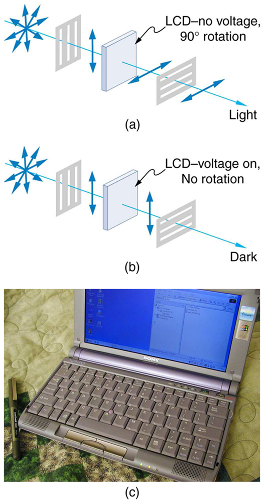
through them by 90º . Furthermore, this property can be turned off by the application of a voltage, as illustrated in Figure 27.47. It is possible to manipulate this characteristic quickly and in small well-defined regions to create the contrast patterns we see in so many LCD devices.
In flat screen LCD televisions, there is a large light at the back of the TV. The light travels to the front screen through millions of tiny units called pixels
(picture elements). One of these is shown in Figure 27.47 (a) and (b). Each unit has three cells, with red, blue, or green filters, each controlled independently. When the voltage across a liquid crystal is switched off, the liquid crystal passes the light through the particular filter. One can vary the
picture contrast by varying the strength of the voltage applied to the liquid crystal.
986 CHAPTER 27 | WAVE OPTICS
Figure 27.47 (a) Polarized light is rotated 90º by a liquid crystal and then passed by a polarizing filter that has its axis perpendicular to the original polarization direction. (b) When a voltage is applied to the liquid crystal, the polarized light is not rotated and is blocked by the filter, making the region dark in comparison with its surroundings. (c) LCDs
can be made color specific, small, and fast enough to use in laptop computers and TVs. (credit: Jon Sullivan)
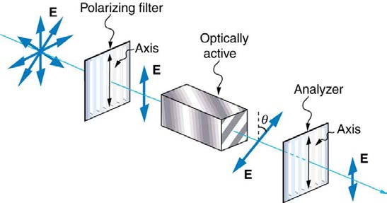
Many crystals and solutions rotate the plane of polarization of light passing through them. Such substances are said to be optically active. Examples
include sugar water, insulin, and collagen (see Figure 27.48). In addition to depending on the type of substance, the amount and direction of rotation depends on a number of factors. Among these is the concentration of the substance, the distance the light travels through it, and the wavelength of
light. Optical activity is due to the asymmetric shape of molecules in the substance, such as being helical. Measurements of the rotation of polarized
light passing through substances can thus be used to measure concentrations, a standard technique for sugars. It can also give information on the
shapes of molecules, such as proteins, and factors that affect their shapes, such as temperature and pH.
Figure 27.48 Optical activity is the ability of some substances to rotate the plane of polarization of light passing through them. The rotation is detected with a polarizing filter or analyzer.
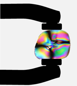
Glass and plastic become optically active when stressed; the greater the stress, the greater the effect. Optical stress analysis on complicated shapes
can be performed by making plastic models of them and observing them through crossed filters, as seen in Figure 27.49. It is apparent that the effect depends on wavelength as well as stress. The wavelength dependence is sometimes also used for artistic purposes.
CHAPTER 27 | WAVE OPTICS 987
Figure 27.49 Optical stress analysis of a plastic lens placed between crossed polarizers. (credit: Infopro, Wikimedia Commons)
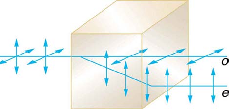
Another interesting phenomenon associated with polarized light is the ability of some crystals to split an unpolarized beam of light into two. Such
crystals are said to be birefringent (see Figure 27.50
Describe what you're looking for in as much detail as you'd like.
Our AI reads your request and finds the best matching books for you.
Popular searches:
Join 2.9 million readers and get unlimited free ebooks