Which assumptions are unreasonable or inconsistent?
nm) wavelengths goes from polystyrene to air, striking the surface at a
30.0º incident angle. What is the angle between the colors when they
928 CHAPTER 25 | GEOMETRIC OPTICS
emerge? (b) How far would they have to travel to be separated by 1.00
(a) What is the closest object that can be photographed? (b) What is the
mm?
magnification of this closest object?
32. A parallel beam of light containing orange (610 nm) and violet (410
46. Suppose your 50.0 mm focal length camera lens is 51.0 mm away
nm) wavelengths goes from fused quartz to water, striking the surface
from the film in the camera. (a) How far away is an object that is in focus?
between them at a 60.0º incident angle. What is the angle between the
(b) What is the height of the object if its image is 2.00 cm high?
two colors in water?
47. (a) What is the focal length of a magnifying glass that produces a
33. A ray of 610 nm light goes from air into fused quartz at an incident
magnification of 3.00 when held 5.00 cm from an object, such as a rare
angle of 55.0º . At what incident angle must 470 nm light enter flint glass coin? (b) Calculate the power of the magnifier in diopters. (c) Discuss
how this power compares to those for store-bought reading glasses
to have the same angle of refraction?
(typically 1.0 to 4.0 D). Is the magnifier’s power greater, and should it
34. A narrow beam of light containing red (660 nm) and blue (470 nm)
be?
wavelengths travels from air through a 1.00 cm thick flat piece of crown
48. What magnification will be produced by a lens of power –4.00 D
glass and back to air again. The beam strikes at a 30.0º incident angle.
(such as might be used to correct myopia) if an object is held 25.0 cm
(a) At what angles do the two colors emerge? (b) By what distance are
away?
the red and blue separated when they emerge?
49. In Example 25.7, the magnification of a book held 7.50 cm from a
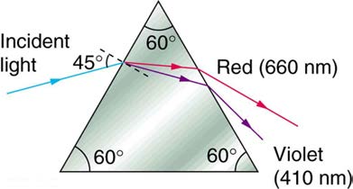
35. A narrow beam of white light enters a prism made of crown glass at a
10.0 cm focal length lens was found to be 3.00. (a) Find the magnification
45.0º incident angle, as shown in Figure 25.57. At what angles, θ R
for the book when it is held 8.50 cm from the magnifier. (b) Do the same
for when it is held 9.50 cm from the magnifier. (c) Comment on the trend
and θ V , do the red (660 nm) and violet (410 nm) components of the
in m as the object distance increases as in these two calculations.
light emerge from the prism?
50. Suppose a 200 mm focal length telephoto lens is being used to
photograph mountains 10.0 km away. (a) Where is the image? (b) What
is the height of the image of a 1000 m high cliff on one of the mountains?
51. A camera with a 100 mm focal length lens is used to photograph the
sun and moon. What is the height of the image of the sun on the film,
given the sun is 1.40×10⁶ km in diameter and is 1.50×10⁸ km
away?
52. Combine thin lens equations to show that the magnification for a thin
lens is determined by its focal length and the object distance and is given
by m = f / ⎛⎝ f − d o⎞⎠ .
Figure 25.57 This prism will disperse the white light into a rainbow of colors. The
incident angle is 45.0º , and the angles at which the red and violet light emerge are
25.7 Image Formation by Mirrors
θ R and θ V .
53. What is the focal length of a makeup mirror that has a power of 1.50
D?
25.6 Image Formation by Lenses
54. Some telephoto cameras use a mirror rather than a lens. What radius
36. What is the power in diopters of a camera lens that has a 50.0 mm
of curvature mirror is needed to replace a 800 mm focal length telephoto
focal length?
lens?
37. Your camera’s zoom lens has an adjustable focal length ranging from
55. (a) Calculate the focal length of the mirror formed by the shiny back
80.0 to 200 mm. What is its range of powers?
of a spoon that has a 3.00 cm radius of curvature. (b) What is its power in
38. What is the focal length of 1.75 D reading glasses found on the rack
diopters?
in a pharmacy?
56. Find the magnification of the heater element in Example 25.9. Note
39. You note that your prescription for new eyeglasses is –4.50 D. What
that its large magnitude helps spread out the reflected energy.
will their focal length be?
57. What is the focal length of a makeup mirror that produces a
40. How far from the lens must the film in a camera be, if the lens has a
magnification of 1.50 when a person’s face is 12.0 cm away? Explicitly
35.0 mm focal length and is being used to photograph a flower 75.0 cm
show how you follow the steps in the Problem-Solving Strategy for
away? Explicitly show how you follow the steps in the Problem-Solving
Strategy for lenses.
58. A shopper standing 3.00 m from a convex security mirror sees his
41. A certain slide projector has a 100 mm focal length lens. (a) How far
image with a magnification of 0.250. (a) Where is his image? (b) What is
away is the screen, if a slide is placed 103 mm from the lens and
the focal length of the mirror? (c) What is its radius of curvature?
produces a sharp image? (b) If the slide is 24.0 by 36.0 mm, what are the
Explicitly show how you follow the steps in the Problem-Solving
dimensions of the image? Explicitly show how you follow the steps in the
Problem-Solving Strategy for lenses.
59. An object 1.50 cm high is held 3.00 cm from a person’s cornea, and
42. A doctor examines a mole with a 15.0 cm focal length magnifying
its reflected image is measured to be 0.167 cm high. (a) What is the
glass held 13.5 cm from the mole (a) Where is the image? (b) What is its
magnification? (b) Where is the image? (c) Find the radius of curvature of
magnification? (c) How big is the image of a 5.00 mm diameter mole?
the convex mirror formed by the cornea. (Note that this technique is used
by optometrists to measure the curvature of the cornea for contact lens
43. How far from a piece of paper must you hold your father’s 2.25 D
fitting. The instrument used is called a keratometer, or curve measurer.)
reading glasses to try to burn a hole in the paper with sunlight?
60. Ray tracing for a flat mirror shows that the image is located a
44. A camera with a 50.0 mm focal length lens is being used to
distance behind the mirror equal to the distance of the object from the
photograph a person standing 3.00 m away. (a) How far from the lens
mirror. This is stated d
must the film be? (b) If the film is 36.0 mm high, what fraction of a 1.75 m
i = –d o , since this is a negative image distance
tall person will fit on it? (c) Discuss how reasonable this seems, based on
(it is a virtual image). (a) What is the focal length of a flat mirror? (b) What
your experience in taking or posing for photographs.
is its power?
45. A camera lens used for taking close-up photographs has a focal
61. Show that for a flat mirror h i = h o , knowing that the image is a
length of 22.0 mm. The farthest it can be placed from the film is 33.0 mm.
distance behind the mirror equal in magnitude to the distance of the
object from the mirror.
CHAPTER 25 | GEOMETRIC OPTICS 929
62. Use the law of reflection to prove that the focal length of a mirror is
half its radius of curvature. That is, prove that f = R / 2 . Note this is
true for a spherical mirror only if its diameter is small compared with its
radius of curvature.
63. Referring to the electric room heater considered in the first example
in this section, calculate the intensity of IR radiation in W/m2 projected
by the concave mirror on a person 3.00 m away. Assume that the heating
element radiates 1500 W and has an area of 100 cm2 , and that half of
the radiated power is reflected and focused by the mirror.
64. Consider a 250-W heat lamp fixed to the ceiling in a bathroom. If the
filament in one light burns out then the remaining three still work.
Construct a problem in which you determine the resistance of each
filament in order to obtain a certain intensity projected on the bathroom
floor. The ceiling is 3.0 m high. The problem will need to involve concave
mirrors behind the filaments. Your instructor may wish to guide you on the
level of complexity to consider in the electrical components.
930 CHAPTER 25 | GEOMETRIC OPTICS
CHAPTER 26 | VISION AND OPTICAL INSTRUMENTS 931
26
VISION AND OPTICAL INSTRUMENTS
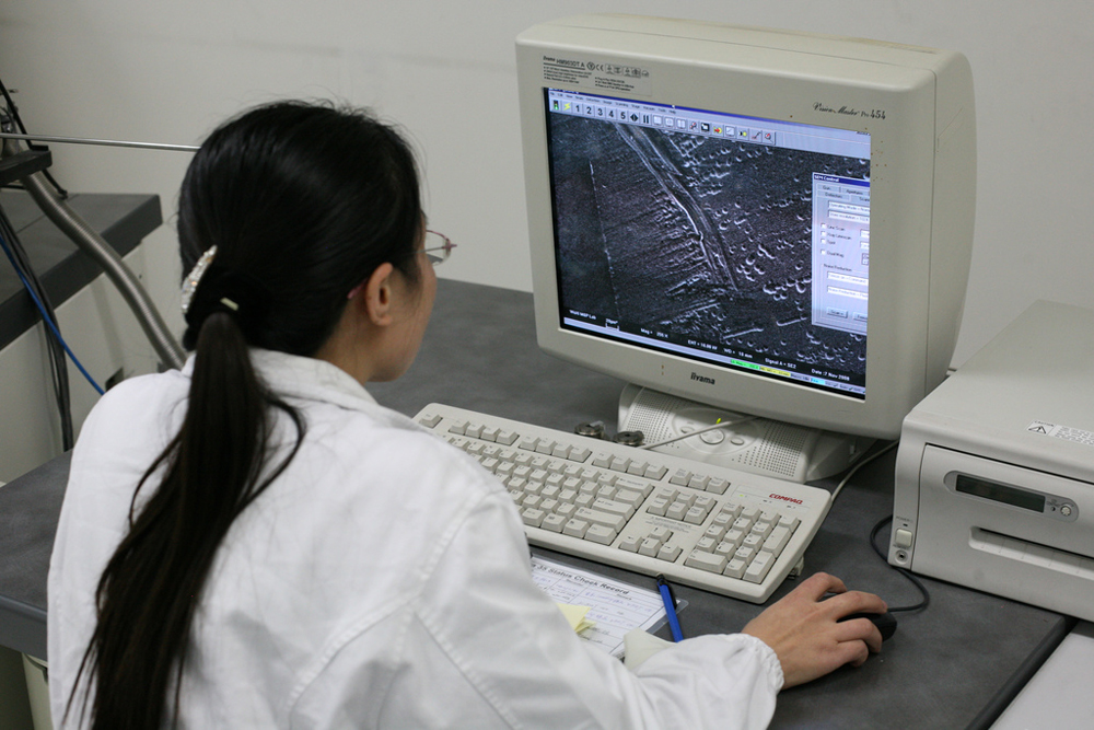
Figure 26.1 A scientist examines minute details on the surface of a disk drive at a magnification of 100,000 times. The image was produced using an electron microscope.
(credit: Robert Scoble)
Learning Objectives
• Explain the image formation by the eye.
• Explain why peripheral images lack detail and color.
• Define refractive indices.
• Analyze the accommodation of the eye for distant and near vision.
• Identify and discuss common vision defects.
• Explain nearsightedness and farsightedness corrections.
• Explain laser vision correction.
• Explain the simple theory of color vision.
• Outline the coloring properties of light sources.
• Describe the retinex theory of color vision.
• Investigate different types of microscopes.
• Learn how image is formed in a compound microscope.
• Outline the invention of a telescope.
• Describe the working of a telescope.
• Describe optical aberration.
Introduction to Vision and Optical Instruments
Explore how the image on the computer screen is formed. How is the image formation on the computer screen different from the image formation in
your eye as you look down the microscope? How can videos of living cell processes be taken for viewing later on, and by many different people?
932 CHAPTER 26 | VISION AND OPTICAL INSTRUMENTS
Seeing faces and objects we love and cherish is a delight—one’s favorite teddy bear, a picture on the wall, or the sun rising over the mountains.
Intricate images help us understand nature and are invaluable for developing techniques and technologies in order to improve the quality of life. The
image of a red blood cell that almost fills the cross-sectional area of a tiny capillary makes us wonder how blood makes it through and not get stuck.
We are able to see bacteria and viruses and understand their structure. It is the knowledge of physics that provides fundamental understanding and
models required to develop new techniques and instruments. Therefore, physics is called an enabling science—a science that enables development
and advancement in other areas. It is through optics and imaging that physics enables advancement in major areas of biosciences. This chapter
illustrates the enabling nature of physics through an understanding of how a human eye is able to see and how we are able to use optical instruments
to see beyond what is possible with the naked eye. It is convenient to categorize these instruments on the basis of geometric optics (see Geometric
Optics) and wave optics (see Wave Optics).
26.1 Physics of the Eye
The eye is perhaps the most interesting of all optical instruments. The eye is remarkable in how it forms images and in the richness of detail and color
it can detect. However, our eyes commonly need some correction, to reach what is called “normal” vision, but should be called ideal rather than
normal. Image formation by our eyes and common vision correction are easy to analyze with the optics discussed in Geometric Optics.
Figure 26.2 shows the basic anatomy of the eye. The cornea and lens form a system that, to a good approximation, acts as a single thin lens. For
clear vision, a real image must be projected onto the light-sensitive retina, which lies at a fixed distance from the lens. The lens of the eye adjusts its
power to produce an image on the retina for objects at different distances. The center of the image falls on the fovea, which has the greatest density
of light receptors and the greatest acuity (sharpness) in the visual field. The variable opening (or pupil) of the eye along with chemical adaptation
allows the eye to detect light intensities from the lowest observable to 1010 times greater (without damage). This is an incredible range of detection.
Our eyes perform a vast number of functions, such as sense direction, movement, sophisticated colors, and distance. Processing of visual nerve
impulses begins with interconnections in the retina and continues in the brain. The optic nerve conveys signals received by the eye to the brain.
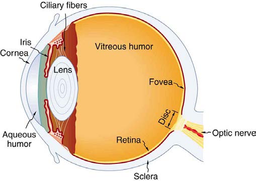
Figure 26.2 The cornea and lens of an eye act together to form a real image on the light-sensing retina, which has its densest concentration of receptors in the fovea and a
blind spot over the optic nerve. The power of the lens of an eye is adjustable to provide an image on the retina for varying object distances. Layers of tissues with varying
indices of refraction in the lens are shown here. However, they have been omitted from other pictures for clarity.
Refractive indices are crucial to image formation using lenses. Table 26.1 shows refractive indices relevant to the eye. The biggest change in the
refractive index, and bending of rays, occurs at the cornea rather than the lens. The ray diagram in Figure 26.3 shows image formation by the cornea and lens of the eye. The rays bend according to the refractive indices provided in Table 26.1. The cornea provides about two-thirds of the power of the eye, owing to the fact that speed of light changes considerably while traveling from air into cornea. The lens provides the remaining power
needed to produce an image on the retina. The cornea and lens can be treated as a single thin lens, even though the light rays pass through several
layers of material (such as cornea, aqueous humor, several layers in the lens, and vitreous humor), changing direction at each interface. The image
formed is much like the one produced by a single convex lens. This is a case 1 image. Images formed in the eye are inverted but the brain inverts
them once more to make them seem upright.
Table 26.1 Refractive Indices Relevant to the Eye
Material
Index of Refraction
Water
1.33
Air
1.0
Cornea
1.38
Aqueous humor 1.34
Lens
1.41 average (varies throughout the lens, greatest in center)
Vitreous humor 1.34
CHAPTER 26 | VISION AND OPTICAL INSTRUMENTS 933
Figure 26.3 An image is formed on the retina with light rays converging most at the cornea and upon entering and exiting the lens. Rays from the top and bottom of the object
are traced and produce an inverted real image on the retina. The distance to the object is drawn smaller than scale.
As noted, the image must fall precisely on the retina to produce clear vision — that is, the image distance d i must equal the lens-to-retina distance.
Because the lens-to-retina distance does not change, the image distance d i must be the same for objects at all distances. The eye manages this by
varying the power (and focal length) of the lens to accommodate for objects at various distances. The process of adjusting the eye’s focal length is
called accommodation. A person with normal (ideal) vision can see objects clearly at distances ranging from 25 cm to essentially infinity. However,
although the near point (the shortest distance at which a sharp focus can be obtained) increases with age (becoming meters for some older people),
we will consider it to be 25 cm in our treatment here.
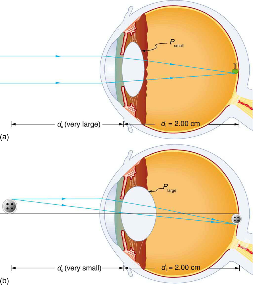
Figure 26.4 shows the accommodation of the eye for distant and near vision. Since light rays from a nearby object can diverge and still enter the eye, the lens must be more converging (more powerful) for close vision than for distant vision. To be more converging, the lens is made thicker by the
action of the ciliary muscle surrounding it. The eye is most relaxed when viewing distant objects, one reason that microscopes and telescopes are
designed to produce distant images. Vision of very distant objects is called totally relaxed, while close vision is termed accommodated, with the
closest vision being fully accommodated.
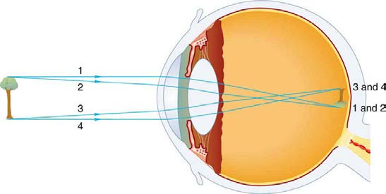
Figure 26.4 Relaxed and accommodated vision for distant and close objects. (a) Light rays from the same point on a distant object must be nearly parallel while entering the
eye and more easily converge to produce an image on the retina. (b) Light rays from a nearby object can diverge more and still enter the eye. A more powerful lens is needed
to converge them on the retina than if they were parallel.
934 CHAPTER 26 | VISION AND OPTICAL INSTRUMENTS
We will use the thin lens equations to examine image formation by the eye quantitatively. First, note the power of a lens is given as p = 1 / f , so we
rewrite the thin lens equations as
(26.1)
P = 1
d + 1
o
d i
and
h
(26.2)
i
h = − d i = m.
o
d o
We understand that d i must equal the lens-to-retina distance to obtain clear vision, and that normal vision is possible for objects at distances
d o = 25 cm to infinity.
Take-Home Experiment: The Pupil
Look at the central transparent area of someone’s eye, the pupil, in normal room light. Estimate the diameter of the pupil. Now turn off the lights
and darken the room. After a few minutes turn on the lights and promptly estimate the diameter of the pupil. What happens to the pupil as the
eye adjusts to the room light? Explain your observations.
The eye can detect an impressive amount of detail, considering how small the image is on the retina. To get some idea of how small the image can
be, consider the following example.
Example 26.1 Size of Image on Retina
What is the size of the image on the retina of a 1.20×10⁻² cm diameter human hair, held at arm’s length (60.0 cm) away? Take the lens-to-
retina distance to be 2.00 cm.
Strategy
We want to find the height of the image h i , given the height of the object is h o = 1.20×10⁻² cm. We also know that the object is 60.0 cm
away, so that d o = 60.0 cm . For clear vision, the image distance must equal the lens-to-retina distance, and so d i = 2.00 cm . The equation
h i
h = − d i = m can be used to find h
o
d o
i with the known information.
Solution
h
The only unknown variable in the equation
i
h = − d i = m is h
o
d o
i :
h
(26.3)
i
h = − d i .
o
d o
Rearranging to isolate h i yields
(26.4)
h i = − h o ⋅ d i
d .
o
Substituting the known values gives
(26.5)
h i = −(1.20×10⁻² cm)2.00 cm
60.0 cm
= −4.00×10⁻⁴ cm.
Discussion
This truly small image is not the smallest discernible—that is, the limit to visual acuity is even smaller than this. Limitations on visual acuity have
to do with the wave properties of light and will be discussed in the next chapter. Some limitation is also due to the inherent anatomy of the eye
and processing that occurs in our brain.
Example 26.2 Power Range of the Eye
Calculate the power of the eye when viewing objects at the greatest and smallest distances possible with normal vision, assuming a lens-to-
retina distance of 2.00 cm (a typical value).
Strategy
CHAPTER 26 | VISION AND OPTICAL INSTRUMENTS 935
For clear vision, the image must be on the retina, and so d i = 2.00 cm here. For distant vision, d o ≈ ∞ , and for close vision,
d o = 25.0 cm , as discussed earlier. The equation P = 1 d + 1 as written just above, can be used directly to solve for P in both cases,
o
d i
since we know d i and d o . Power has units of diopters, where 1 D = 1/m , and so we should express all distances in meters.
Solution
For distant vision,
(26.6)
P = 1
d + 1 = 1
o
d
∞ +
1
i
0.0200 m.
Since 1 / ∞ = 0 , this gives
P
(26.7)
= 0 + 50.0 / m = 50.0 D (distant vision).
Now, for close vision,
(26.8)
P = 1
d + 1 =
1
o
d i 0.250 m +
1
0.0200 m
= 4.00
m + 50.0
m = 4.00 D + 50.0 D
Describe what you're looking for in as much detail as you'd like.
Our AI reads your request and finds the best matching books for you.
Popular searches:
Join 2.9 million readers and get unlimited free ebooks