1
d + 1 = 1
o
d i f .
Rearranging to isolate d o gives
(25.47)
1
d = 1
.
o
f − 1 d i
Entering known quantities gives a value for 1/ d o :
(25.48)
1
d =
1
o
0.250 m − 1
3.00 m = 3.667
m .
This must be inverted to find d o :
(25.49)
d o = 1 m
3.667 = 27.3 cm.
Discussion
Note that the object (the filament) is farther from the mirror than the mirror’s focal length. This is a case 1 image ( d o > f and f positive),
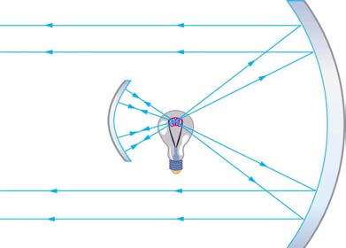
consistent with the fact that a real image is formed. You will get the most concentrated thermal energy directly in front of the mirror and 3.00 m
away from it. Generally, this is not desirable, since it could cause burns. Usually, you want the rays to emerge parallel, and this is accomplished
by having the filament at the focal point of the mirror.
Note that the filament here is not much farther from the mirror than its focal length and that the image produced is considerably farther away.
This is exactly analogous to a slide projector. Placing a slide only slightly farther away from the projector lens than its focal length produces an
image significantly farther away. As the object gets closer to the focal distance, the image gets farther away. In fact, as the object distance
approaches the focal length, the image distance approaches infinity and the rays are sent out parallel to one another.
Example 25.10 Solar Electric Generating System
One of the solar technologies used today for generating electricity is a device (called a parabolic trough or concentrating collector) that
concentrates the sunlight onto a blackened pipe that contains a fluid. This heated fluid is pumped to a heat exchanger, where its heat energy is
transferred to another system that is used to generate steam—and so generate electricity through a conventional steam cycle. Figure 25.44
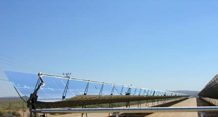
CHAPTER 25 | GEOMETRIC OPTICS 919
shows such a working system in southern California. Concave mirrors are used to concentrate the sunlight onto the pipe. The mirror has the
approximate shape of a section of a cylinder. For the problem, assume that the mirror is exactly one-quarter of a full cylinder.
a. If we wish to place the fluid-carrying pipe 40.0 cm from the concave mirror at the mirror’s focal point, what will be the radius of curvature of
the mirror?
b. Per meter of pipe, what will be the amount of sunlight concentrated onto the pipe, assuming the insolation (incident solar radiation) is
0.900 kW/m2 ?
c. If the fluid-carrying pipe has a 2.00-cm diameter, what will be the temperature increase of the fluid per meter of pipe over a period of one
minute? Assume all the solar radiation incident on the reflector is absorbed by the pipe, and that the fluid is mineral oil.
Strategy
To solve an Integrated Concept Problem we must first identify the physical principles involved. Part (a) is related to the current topic. Part (b)
involves a little math, primarily geometry. Part (c) requires an understanding of heat and density.
Solution to (a)
To a good approximation for a concave or semi-spherical surface, the point where the parallel rays from the sun converge will be at the focal
point, so R = 2 f = 80.0 cm .
Solution to (b)
The insolation is 900 W/m2 . We must find the cross-sectional area A of the concave mirror, since the power delivered is 900 W/m2×A .
The mirror in this case is a quarter-section of a cylinder, so the area for a length L of the mirror is A = 14(2 πR)L . The area for a length of 1.00
m is then
(25.50)
A = π 2 R(1.00 m) = (3.14)
2 (0.800 m)(1.00 m) = 1.26 m2.
The insolation on the 1.00-m length of pipe is then
(25.51)
⎛
⎞⎛
⎝9.00×10² W
m2⎠⎝1.26 m2⎞⎠ = 1130 W.
Solution to (c)
The increase in temperature is given by Q = mcΔ T . The mass m of the mineral oil in the one-meter section of pipe is
2
(25.52)
m = ρ V = ρπ⎛ d⎞
⎝2⎠ (1.00 m)
= ⎛⎝8.00×10² kg/m3⎞⎠(3.14)(0.0100 m)2(1.00 m)
= 0.251 kg.
Therefore, the increase in temperature in one minute is
(25.53)
Δ T = Q / m c
=
(1130 W)(60.0 s)
(0.251 kg)(1670 J·kg/ºC)
= 162ºC.
Discussion for (c)
An array of such pipes in the California desert can provide a thermal output of 250 MW on a sunny day, with fluids reaching temperatures as high
as 400ºC . We are considering only one meter of pipe here, and ignoring heat losses along the pipe.
Figure 25.44 Parabolic trough collectors are used to generate electricity in southern California. (credit: kjkolb, Wikimedia Commons)
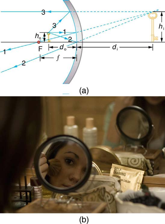
What happens if an object is closer to a concave mirror than its focal length? This is analogous to a case 2 image for lenses ( d o < f and f
positive), which is a magnifier. In fact, this is how makeup mirrors act as magnifiers. Figure 25.45(a) uses ray tracing to locate the image of an
object placed close to a concave mirror. Rays from a common point on the object are reflected in such a manner that they appear to be coming
920 CHAPTER 25 | GEOMETRIC OPTICS
from behind the mirror, meaning that the image is virtual and cannot be projected. As with a magnifying glass, the image is upright and larger
than the object. This is a case 2 image for mirrors and is exactly analogous to that for lenses.
Figure 25.45 (a) Case 2 images for mirrors are formed when a converging mirror has an object closer to it than its focal length. Ray 1 approaches parallel to the axis, ray
2 strikes the center of the mirror, and ray 3 approaches the mirror as if it came from the focal point. (b) A magnifying mirror showing the reflection. (credit: Mike Melrose,
Flickr)
All three rays appear to originate from the same point after being reflected, locating the upright virtual image behind the mirror and showing it to
be larger than the object. (b) Makeup mirrors are perhaps the most common use of a concave mirror to produce a larger, upright image.
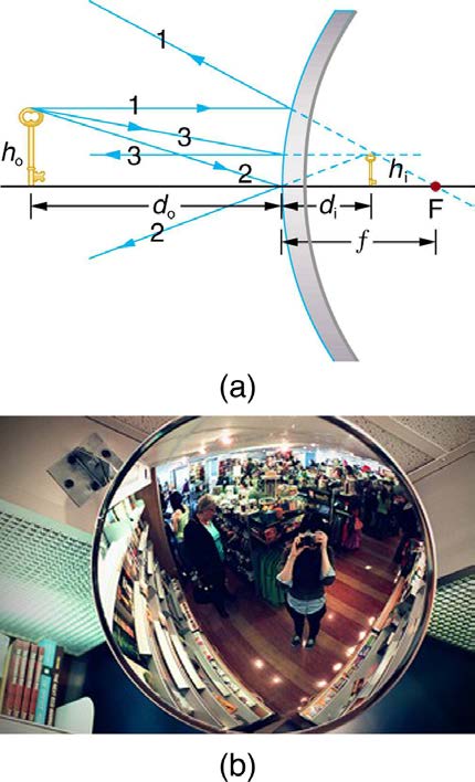
A convex mirror is a diverging mirror ( f is negative) and forms only one type of image. It is a case 3 image—one that is upright and smaller
than the object, just as for diverging lenses. Figure 25.46(a) uses ray tracing to illustrate the location and size of the case 3 image for mirrors.
Since the image is behind the mirror, it cannot be projected and is thus a virtual image. It is also seen to be smaller than the object.
CHAPTER 25 | GEOMETRIC OPTICS 921
Figure 25.46 Case 3 images for mirrors are formed by any convex mirror. Ray 1 approaches parallel to the axis, ray 2 strikes the center of the mirror, and ray 3
approaches toward the focal point. All three rays appear to originate from the same point after being reflected, locating the upright virtual image behind the mirror and
showing it to be smaller than the object. (b) Security mirrors are convex, producing a smaller, upright image. Because the image is smaller, a larger area is imaged
compared to what would be observed for a flat mirror (and hence security is improved). (credit: Laura D’Alessandro, Flickr)
Example 25.11 Image in a Convex Mirror
A keratometer is a device used to measure the curvature of the cornea, particularly for fitting contact lenses. Light is reflected from the cornea,
which acts like a convex mirror, and the keratometer measures the magnification of the image. The smaller the magnification, the smaller the
radius of curvature of the cornea. If the light source is 12.0 cm from the cornea and the image’s magnification is 0.0320, what is the cornea’s
radius of curvature?
Strategy
If we can find the focal length of the convex mirror formed by the cornea, we can find its radius of curvature (the radius of curvature is twice the
focal length of a spherical mirror). We are given that the object distance is d o = 12.0 cm and that m = 0.0320 . We first solve for the image
distance d i , and then for f .
Solution
m = –d i / d o . Solving this expression for d i gives
d
(25.54)
i = − md o.
Entering known values yields
d
(25.55)
i = – (0.0320)(12.0 cm) = –0.384 cm.
(25.56)
1 f = 1 d + 1
o
d i
Substituting known values,
(25.57)
1 f = 1
12.0 cm +
1
−0.384 cm = −2.52
cm .
This must be inverted to find f :
(25.58)
f = cm
– 2.52 = –0.400 cm.
922 CHAPTER 25 | GEOMETRIC OPTICS
The radius of curvature is twice the focal length, so that
R
(25.59)
= 2 ∣ f ∣ = 0.800 cm.
Discussion
Although the focal length f of a convex mirror is defined to be negative, we take the absolute value to give us a positive value for R . The
radius of curvature found here is reasonable for a cornea. The distance from cornea to retina in an adult eye is about 2.0 cm. In practice, many
corneas are not spherical, complicating the job of fitting contact lenses. Note that the image distance here is negative, consistent with the fact
that the image is behind the mirror, where it cannot be projected. In this section’s Problems and Exercises, you will show that for a fixed object
distance, the smaller the radius of curvature, the smaller the magnification.
The three types of images formed by mirrors (cases 1, 2, and 3) are exactly analogous to those formed by lenses, as summarized in the table at
convex lenses, whereas convex mirrors act like concave lenses.
Take-Home Experiment: Concave Mirrors Close to Home
Find a flashlight and identify the curved mirror used in it. Find another flashlight and shine the first flashlight onto the second one, which is turned
off. Estimate the focal length of the mirror. You might try shining a flashlight on the curved mirror behind the headlight of a car, keeping the
headlight switched off, and determine its focal length.
Problem-Solving Strategy for Mirrors
Step 1. Examine the situation to determine that image formation by a mirror is involved.
Step 2. Refer to the Problem-Solving Strategies for Lenses. The same strategies are valid for mirrors as for lenses with one qualification—use the
ray tracing rules for mirrors listed earlier in this section.
Glossary
converging lens: a convex lens in which light rays that enter it parallel to its axis converge at a single point on the opposite side
converging mirror: a concave mirror in which light rays that strike it parallel to its axis converge at one or more points along the axis
corner reflector: an object consisting of two mutually perpendicular reflecting surfaces, so that the light that enters is reflected back exactly
parallel to the direction from which it came
critical angle: incident angle that produces an angle of refraction of 90º
dispersion: spreading of white light into its full spectrum of wavelengths
diverging lens: a concave lens in which light rays that enter it parallel to its axis bend away (diverge) from its axis
diverging mirror: a convex mirror in which light rays that strike it parallel to its axis bend away (diverge) from its axis
fiber optics: transmission of light down fibers of plastic or glass, applying the principle of total internal reflection
focal length: distance from the center of a lens or curved mirror to its focal point
focal point: for a converging lens or mirror, the point at which converging light rays cross; for a diverging lens or mirror, the point from which
diverging light rays appear to originate
geometric optics: part of optics dealing with the ray aspect of light
index of refraction: for a material, the ratio of the speed of light in vacuum to that in the material
law of reflection: angle of reflection equals the angle of incidence
law of reflection: angle of reflection equals the angle of incidence
magnification: ratio of image height to object height
mirror: smooth surface that reflects light at specific angles, forming an image of the person or object in front of it
power: inverse of focal length
rainbow: dispersion of sunlight into a continuous distribution of colors according to wavelength, produced by the refraction and reflection of
sunlight by water droplets in the sky
ray: straight line that originates at some point
real image: image that can be projected
refraction: changing of a light ray’s direction when it passes through variations in matter
virtual image: image that cannot be projected
CHAPTER 25 | GEOMETRIC OPTICS 923
zircon: natural gemstone with a large index of refraction
Section Summary
• A straight line that originates at some point is called a ray.
• The part of optics dealing with the ray aspect of light is called geometric optics.
• Light can travel in three ways from a source to another location: (1) directly from the source through empty space; (2) through various media; (3)
after being reflected from a mirror.
• The angle of reflection equals the angle of incidence.
• A mirror has a smooth surface and reflects light at specific angles.
• Light is diffused when it reflects from a rough surface.
• Mirror images can be photographed and videotaped by instruments.
• The changing of a light ray’s direction when it passes through variations in matter is called refraction.
• The speed of light in vacuum c = 2.9972458×10⁸ m/s ≈ 3.00×10⁸ m/s.
• Index of refraction n = cv , where v is the speed of light in the material, c is the speed of light in vacuum, and n is the index of refraction.
• Snell’s law, the law of refraction, is stated in equation form as n 1 sin θ 1 = n 2 sin θ 2 .
25.4 Total Internal Reflection
• The incident angle that produces an angle of refraction of 90º is called critical angle.
• Total internal reflection is a phenomenon that occurs at the boundary between two mediums, such that if the incident angle in the first medium is
greater than the critical angle, then all the light is reflected back into that medium.
• Fiber optics involves the transmission of light down fibers of plastic or glass, applying the principle of total internal reflection.
• Endoscopes are used to explore the body through various orifices or minor incisions, based on the transmission of light through optical fibers.
• Cladding prevents light from being transmitted between fibers in a bundle.
• Diamonds sparkle due to total internal reflection coupled with a large index of refraction.
25.5 Dispersion: The Rainbow and Prisms
• The spreading of white light into its full spectrum of wavelengths is called dispersion.
• Rainbows are produced by a combination of refraction and reflection and involve the dispersion of sunlight into a continuous distribution of
colors.
• Dispersion produces beautiful rainbows but also causes problems in certain optical systems.
25.6 Image Formation by Lenses
• Light rays entering a converging lens parallel to its axis cross one another at a single point on the opposite side.
• For a converging lens, the focal point is the point at which converging light rays cross; for a diverging lens, the focal point is the point from which
diverging light rays appear to originate.
• The distance from the center of the lens to its focal point is called the focal length f .
• Power P of a lens is defined to be the inverse of its focal length, P = 1 f .
• A lens that causes the light rays to bend away from its axis is called a diverging lens.
• Ray tracing is the technique of graphically determining the paths that light rays take.
• The image in which light rays from one point on the object actually cross at the location of the image and can be projected onto a screen, a
piece of film, or the retina of an eye is called a real image.
h
• Thin lens equations are 1
i
d + 1 = 1
= − d i = m (magnification).
o
d i f and h o
d o
• The distance of the image from the center of the lens is called image distance.
• An image that is on the same side of the lens as the object and cannot be projected on a screen is called a virtual image.
25.7 Image Formation by Mirrors
• The characteristics of an image formed by a flat mirror are: (a) The image and object are the same distance from the mirror, (b) The image is a
virtual image, and (c) The image is situated behind the mirror.
• Image length is half the radius of curvature.
f = R 2
• A convex mirror is a diverging mirror and forms only one type of image, namely a virtual image.
Conceptual Questions
1. Using the law of reflection, explain how powder takes the shine off of a person’s nose. What is the name of the optical effect?
924 CHAPTER 25 | GEOMETRIC OPTICS
2. Diffusion by reflection from a rough surface is described in this chapter. Light can also be diffused by refraction. Describe how this occurs in a
specific situation, such as light interacting with crushed ice.
3. Why is the index of refraction always greater than or equal to 1?
4. Does the fact that the light flash from lightning reaches you before its sound prove that the speed of light is extremely large or simply that it is
greater than the speed of sound? Discuss how you could use this effect to get an estimate of the speed of light.
5. Will light change direction toward or away from the perpendicular when it goes from air to water? Water to glass? Glass to air?
6. Explain why an object in water always appears to be at a depth shallower than it actually is? Why do people sometimes sustain neck and spinal
injuries when diving into unfamiliar ponds or waters?
7. Explain why a person’s legs appear very short when wading in a pool. Justify your explanation with a ray diagram showing the path of rays from
the feet to the eye of an observer who is out of the water.
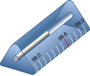
8. Why is the front surface of a thermometer curved as shown?
Figure 25.47 The curved surface of the thermometer serves a purpose.
9. Suppose light were incident from air onto a material that had a negative index of refraction, say –1.3; where does the refracted light ray go?
25.4 Total Internal Reflection
10. A ring with a colorless gemstone is dropped into water. The gemstone becomes invisible when submerged. Can it be a diamond? Explain.
11. A high-quality diamond may be quite clear and colorless, transmitting all visible wavelengths with little absorption. Explain how it can sparkle with
flashes of brilliant color when illuminated by white light.
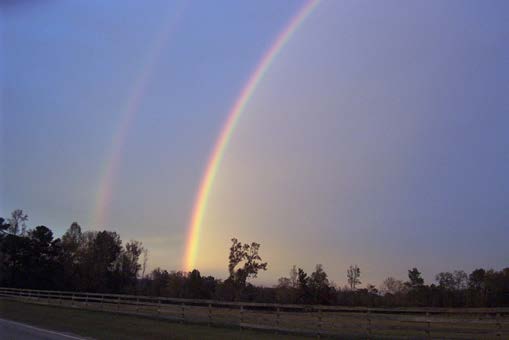
12. Is it possible that total internal reflection plays a role in rainbows? Explain in terms of indices of refraction and angles, perhaps referring to Figure
25.48. Some of us have seen the formation of a double rainbow. Is it physically possible to observe a triple rainbow?
Figure 25.48 Double rainbows are not a very common observance. (credit: InvictusOU812, Flickr)
13. The most common type of mirage is an illusion that light from faraway objects is reflected by a pool of water that is not really there. Mirages are
generally observed in deserts, when there is a hot layer of air near the ground. Given that the refractive index of air is lower for air at higher
temperatures, explain how mirages can be formed.
25.6 Image Formation by Lenses
14. It can be argued that a flat piece of glass, such as in a window, is like a lens with an infinite focal length. If so, where does it form an image? That
is, how are d i and d o related?
15. You can often see a reflection when looking at a sheet of glass, particularly if it is darker on the other side. Explain why you can often see a
double image in such circumstances.
16. When you focus a camera, you adjust the distance of the lens from the film. If the camera lens acts like a thin lens, why can it not be a fixed
distance from the film for both near and distant objects?
17. A thin lens has two focal points, one on either side, at equal distances from its center, and should behave the same for light entering from either
side. Look through your eyeglasses (or those of a friend) backward and forward and comment on whether they are thin lenses.
18. Will the focal length of a lens change when it is submerged in water? Explain.
CHAPTER 25 | GEOMETRIC OPTICS 925
25.7 Image Formation by Mirrors
19. What are the differences between real and virtual images? How can you tell (by looking) whether an image formed by a single lens or mirror is
real or virtual?
20. Can you see a virtual image? Can you photograph one? Can one be projected onto a screen with additional lenses or mirrors? Explain your
responses.
21. Is it necessary to project a real image onto a screen for it to exist?
Describe what you're looking for in as much detail as you'd like.
Our AI reads your request and finds the best matching books for you.
Popular searches:
Join 2.9 million readers and get unlimited free ebooks