906 CHAPTER 25 | GEOMETRIC OPTICS
(25.20)
P = 1 f.
Power P
The power P of a lens is defined to be the inverse of its focal length. In equation form, this is
(25.21)
P = 1 f.
where f is the focal length of the lens, which must be given in meters (and not cm or mm). The power of a lens P has the unit diopters (D),
provided that the focal length is given in meters. That is, 1 D = 1 / m , or 1 m−1 . (Note that this power (optical power, actually) is not the same
as power in watts defined in Work, Energy, and Energy Resources. It is a concept related to the effect of optical devices on light.) Optometrists
prescribe common spectacles and contact lenses in units of diopters.
Example 25.5 What is the Power of a Common Magnifying Glass?
Suppose you take a magnifying glass out on a sunny day and you find that it concentrates sunlight to a small spot 8.00 cm away from the lens.
What are the focal length and power of the lens?
Strategy
The situation here is the same as those shown in Figure 25.27 and Figure 25.28. The Sun is so far away that the Sun’s rays are nearly parallel when they reach Earth. The magnifying glass is a convex (or converging) lens, focusing the nearly parallel rays of sunlight. Thus the focal length
of the lens is the distance from the lens to the spot, and its power is the inverse of this distance (in m).
Solution
The focal length of the lens is the distance from the center of the lens to the spot, given to be 8.00 cm. Thus,
f
(25.22)
= 8.00 cm.
To find the power of the lens, we must first convert the focal length to meters; then, we substitute this value into the equation for power. This
gives
(25.23)
P = 1 f =
1
0.0800 m = 12.5 D.
Discussion
This is a relatively powerful lens. The power of a lens in diopters should not be confused with the familiar concept of power in watts. It is an
unfortunate fact that the word “power” is used for two completely different concepts. If you examine a prescription for eyeglasses, you will note
lens powers given in diopters. If you examine the label on a motor, you will note energy consumption rate given as a power in watts.
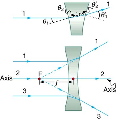
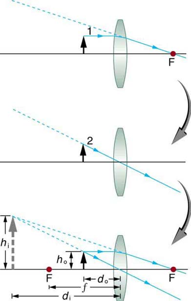
Figure 25.29 shows a concave lens and the effect it has on rays of light that enter it parallel to its axis (the path taken by ray 2 in the figure is the axis of the lens). The concave lens is a diverging lens, because it causes the light rays to bend away (diverge) from its axis. In this case, the lens has
been shaped so that all light rays entering it parallel to its axis appear to originate from the same point, F , defined to be the focal point of a diverging
lens. The distance from the center of the lens to the focal point is again called the focal length f of the lens. Note that the focal length and power of
a diverging lens are defined to be negative. For example, if the distance to F in Figure 25.29 is 5.00 cm, then the focal length is f = –5.00 cm and the power of the lens is P = –20 D . An expanded view of the path of one ray through the lens is shown in the figure to illustrate how the shape
of the lens, together with the law of refraction, causes the ray to follow its particular path and be diverged.
CHAPTER 25 | GEOMETRIC OPTICS 907
Figure 25.29 Rays of light entering a diverging lens parallel to its axis are diverged, and all appear to originate at its focal point F . The dashed lines are not rays—they
indicate the directions from which the rays appear to come. The focal length f of a diverging lens is negative. An expanded view of the path taken by ray 1 shows the
perpendiculars and the angles of incidence and refraction at both surfaces.
Diverging Lens
A lens that causes the light rays to bend away from its axis is called a diverging lens.
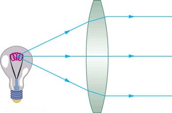
As noted in the initial discussion of the law of refraction in The Law of Refraction, the paths of light rays are exactly reversible. This means that the direction of the arrows could be reversed for all of the rays in Figure 25.27 and Figure 25.29. For example, if a point light source is placed at the focal point of a convex lens, as shown in Figure 25.30, parallel light rays emerge from the other side.
Figure 25.30 A small light source, like a light bulb filament, placed at the focal point of a convex lens, results in parallel rays of light emerging from the other side. The paths are exactly the reverse of those shown in Figure 25.27. This technique is used in lighthouses and sometimes in traffic lights to produce a directional beam of light from a source that emits light in all directions.
Ray Tracing and Thin Lenses
Ray tracing is the technique of determining or following (tracing) the paths that light rays take. For rays passing through matter, the law of refraction
is used to trace the paths. Here we use ray tracing to help us understand the action of lenses in situations ranging from forming images on film to
magnifying small print to correcting nearsightedness. While ray tracing for complicated lenses, such as those found in sophisticated cameras, may
require computer techniques, there is a set of simple rules for tracing rays through thin lenses. A thin lens is defined to be one whose thickness
allows rays to refract, as illustrated in Figure 25.27, but does not allow properties such as dispersion and aberrations. An ideal thin lens has two refracting surfaces but the lens is thin enough to assume that light rays bend only once. A thin symmetrical lens has two focal points, one on either
side and both at the same distance from the lens. (See Figure 25.31.) Another important characteristic of a thin lens is that light rays through its
center are deflected by a negligible amount, as seen in Figure 25.32.
Thin Lens
A thin lens is defined to be one whose thickness allows rays to refract but does not allow properties such as dispersion and aberrations.
Take-Home Experiment: A Visit to the Optician
Look through your eyeglasses (or those of a friend) backward and forward and comment on whether they act like thin lenses.
908 CHAPTER 25 | GEOMETRIC OPTICS
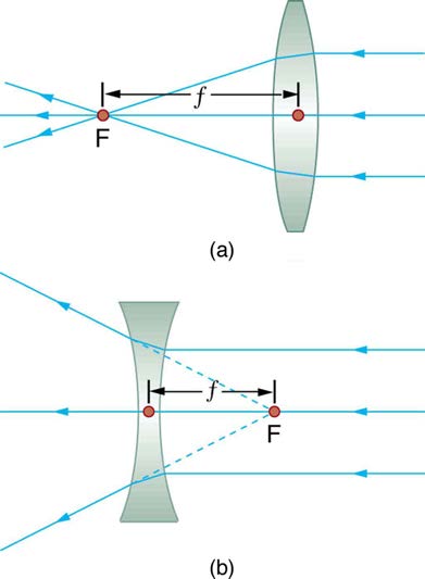
Figure 25.31 Thin lenses have the same focal length on either side. (a) Parallel light rays entering a converging lens from the right cross at its focal point on the left. (b)
Parallel light rays entering a diverging lens from the right seem to come from the focal point on the right.
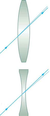
Figure 25.32 The light ray through the center of a thin lens is deflected by a negligible amount and is assumed to emerge parallel to its original path (shown as a shaded line).
Using paper, pencil, and a straight edge, ray tracing can accurately describe the operation of a lens. The rules for ray tracing for thin lenses are
based on the illustrations already discussed:
1. A ray entering a converging lens parallel to its axis passes through the focal point F of the lens on the other side. (See rays 1 and 3 in Figure
25.27.)
2. A ray entering a diverging lens parallel to its axis seems to come from the focal point F. (See rays 1 and 3 in Figure 25.29.)
3. A ray passing through the center of either a converging or a diverging lens does not change direction. (See Figure 25.32, and see ray 2 in
Figure 25.27 and Figure 25.29.)
4. A ray entering a converging lens through its focal point exits parallel to its axis. (The reverse of rays 1 and 3 in Figure 25.27.)
5. A ray that enters a diverging lens by heading toward the focal point on the opposite side exits parallel to the axis. (The reverse of rays 1 and 3 in
Rules for Ray Tracing
1. A ray entering a converging lens parallel to its axis passes through the focal point F of the lens on the other side.
2. A ray entering a diverging lens parallel to its axis seems to come from the focal point F.
3. A ray passing through the center of either a converging or a diverging lens does not change direction.
4. A ray entering a converging lens through its focal point exits parallel to its axis.
5. A ray that enters a diverging lens by heading toward the focal point on the opposite side exits parallel to the axis.
CHAPTER 25 | GEOMETRIC OPTICS 909
Image Formation by Thin Lenses
In some circumstances, a lens forms an obvious image, such as when a movie projector casts an image onto a screen. In other cases, the image is
less obvious. Where, for example, is the image formed by eyeglasses? We will use ray tracing for thin lenses to illustrate how they form images, and
we will develop equations to describe the image formation quantitatively.
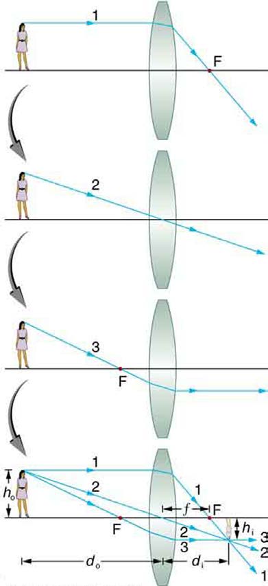
Consider an object some distance away from a converging lens, as shown in Figure 25.33. To find the location and size of the image formed, we
trace the paths of selected light rays originating from one point on the object, in this case the top of the person’s head. The figure shows three rays
from the top of the object that can be traced using the ray tracing rules given above. (Rays leave this point going in many directions, but we
concentrate on only a few with paths that are easy to trace.) The first ray is one that enters the lens parallel to its axis and passes through the focal
point on the other side (rule 1). The second ray passes through the center of the lens without changing direction (rule 3). The third ray passes through
the nearer focal point on its way into the lens and leaves the lens parallel to its axis (rule 4). The three rays cross at the same point on the other side
of the lens. The image of the top of the person’s head is located at this point. All rays that come from the same point on the top of the person’s head
are refracted in such a way as to cross at the point shown. Rays from another point on the object, such as her belt buckle, will also cross at another
common point, forming a complete image, as shown. Although three rays are traced in Figure 25.33, only two are necessary to locate the image. It is best to trace rays for which there are simple ray tracing rules. Before applying ray tracing to other situations, let us consider the example shown in
Figure 25.33 in more detail.
Figure 25.33 Ray tracing is used to locate the image formed by a lens. Rays originating from the same point on the object are traced—the three chosen rays each follow one
of the rules for ray tracing, so that their paths are easy to determine. The image is located at the point where the rays cross. In this case, a real image—one that can be
projected on a screen—is formed.
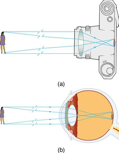
The image formed in Figure 25.33 is a real image, meaning that it can be projected. That is, light rays from one point on the object actually cross at the location of the image and can be projected onto a screen, a piece of film, or the retina of an eye, for example. Figure 25.34 shows how such an image would be projected onto film by a camera lens. This figure also shows how a real image is projected onto the retina by the lens of an eye. Note
that the image is there whether it is projected onto a screen or not.
Real Image
The image in which light rays from one point on the object actually cross at the location of the image and can be projected onto a screen, a piece
of film, or the retina of an eye is called a real image.
910 CHAPTER 25 | GEOMETRIC OPTICS
Figure 25.34 Real images can be projected. (a) A real image of the person is projected onto film. (b) The converging nature of the multiple surfaces that make up the eye
result in the projection of a real image on the retina.
Several important distances appear in Figure 25.33. We define d o to be the object distance, the distance of an object from the center of a lens.
Image distance d i is defined to be the distance of the image from the center of a lens. The height of the object and height of the image are given
the symbols h o and h i , respectively. Images that appear upright relative to the object have heights that are positive and those that are inverted
have negative heights. Using the rules of ray tracing and making a scale drawing with paper and pencil, like that in Figure 25.33, we can accurately
describe the location and size of an image. But the real benefit of ray tracing is in visualizing how images are formed in a variety of situations. To
obtain numerical information, we use a pair of equations that can be derived from a geometric analysis of ray tracing for thin lenses. The thin lens
equations are
(25.24)
1
d + 1 = 1
o
d i f
and
h
(25.25)
i
h = − d i = m.
o
d o
We define the ratio of image height to object height ( h i / h o ) to be the magnification m . (The minus sign in the equation above will be discussed
shortly.) The thin lens equations are broadly applicable to all situations involving thin lenses (and “thin” mirrors, as we will see later). We will explore
many features of image formation in the following worked examples.
Image Distance
The distance of the image from the center of the lens is called image distance.
Thin Lens Equations and Magnification
(25.26)
1
d + 1 = 1
o
d i f
h
(25.27)
i
h = − d i = m
o
d o
Example 25.6 Finding the Image of a Light Bulb Filament by Ray Tracing and by the Thin Lens Equations
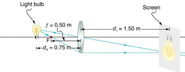
A clear glass light bulb is placed 0.750 m from a convex lens having a 0.500 m focal length, as shown in Figure 25.35. Use ray tracing to get an
approximate location for the image. Then use the thin lens equations to calculate (a) the location of the image and (b) its magnification. Verify
that ray tracing and the thin lens equations produce consistent results.
CHAPTER 25 | GEOMETRIC OPTICS 911
Figure 25.35 A light bulb placed 0.750 m from a lens having a 0.500 m focal length produces a real image on a poster board as discussed in the example above. Ray
tracing predicts the image location and size.
Strategy and Concept
Since the object is placed farther away from a converging lens than the focal length of the lens, this situation is analogous to those illustrated in
Figure 25.33 and Figure 25.34. Ray tracing to scale should produce similar results for d i . Numerical solutions for d i and m can be obtained using the thin lens equations, noting that d o = 0.750 m and f = 0.500 m .
Solutions (Ray tracing)
The ray tracing to scale in Figure 25.35 shows two rays from a point on the bulb’s filament crossing about 1.50 m on the far side of the lens.
Thus the image distance d i is about 1.50 m. Similarly, the image height based on ray tracing is greater than the object height by about a factor
of 2, and the image is inverted. Thus m is about –2. The minus sign indicates that the image is inverted.
The thin lens equations can be used to find d i from the given information:
(25.28)
1
d + 1 = 1
o
d i f .
Rearranging to isolate d i gives
(25.29)
1 d = 1
.
i
f − 1
d o
Entering known quantities gives a value for 1 / d i :
(25.30)
1 d = 1
i
0.500 m −
1
0.750 m = 0.667
m .
This must be inverted to find d i :
(25.31)
d i = m
0.667 = 1.50 m.
Note that another way to find d i is to rearrange the equation:
(25.32)
1 d = 1
.
i
f − 1
d o
This yields the equation for the image distance as:
(25.33)
d i = fd o
d o − f .
Note that there is no inverting here.
The thin lens equations can be used to find the magnification m , since both d i and d o are known. Entering their values gives
(25.34)
m = – d i
d = – 1.50 m
o
0.750 m = – 2.00.
Discussion
Note that the minus sign causes the magnification to be negative when the image is inverted. Ray tracing and the use of the thin lens equations
produce consistent results. The thin lens equations give the most precise results, being limited only by the accuracy of the given information. Ray
tracing is limited by the accuracy with which you can draw, but it is highly useful both conceptually and visually.
Real images, such as the one considered in the previous example, are formed by converging lenses whenever an object is farther from the lens than
its focal length. This is true for movie projectors, cameras, and the eye. We shall refer to these as case 1 images. A case 1 image is formed when
d o > f and f is positive, as in Figure 25.36(a). (A summary of the three cases or types of image formation appears at the end of this section.)
912 CHAPTER 25 | GEOMETRIC OPTICS
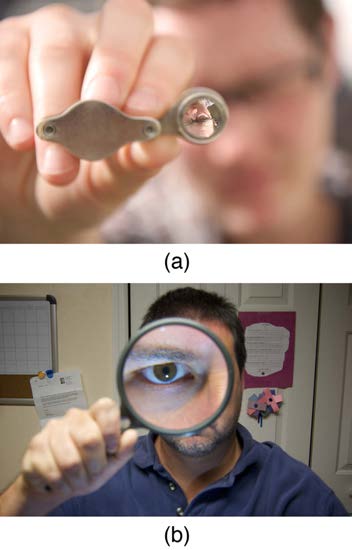
A different type of image is formed when an object, such as a person's face, is held close to a convex lens. The image is upright and larger than the
object, as seen in Figure 25.36(b), and so the lens is called a magnifier. If you slowly pull the magnifier away from the face, you will see that the magnification steadily increases until the image begins to blur. Pulling the magnifier even farther away produces an inverted image as seen in Figure
25.36(a). The distance at which the image blurs, and beyond which it inverts, is the focal length of the lens. To use a convex lens as a magnifier, the object must be closer to the converging lens than its focal length. This is called a case 2 image. A case 2 image is formed when d o < f and f is positive.
Figure 25.36 (a) When a converging lens is held farther away from the face than the lens’s focal length, an inverted image is formed. This is a case 1 image. Note that the
image is in focus but the face is not, because the image is much closer to the camera taking this photograph than the face. (credit: DaMongMan, Flickr) (b) A magnified image
of a face is produced by placing it closer to the converging lens than its focal length. This is a case 2 image. (credit: Casey Fleser, Flickr)
Figure 25.37 uses ray tracing to show how an image is formed when an object is held closer to a converging lens than its focal length. Rays coming
from a common point on the object continue to diverge after passing through the lens, but all appear to originate from a point at the location of the
image. The image is on the same side of the lens as the object and is farther away from the lens than the object. This image, like all case 2 images,
cannot be projected and, hence, is called a virtual image. Light rays only appear to originate at a virtual image; they do not actually pass through
that location in space. A screen placed at the location of a virtual image will receive only diffuse light from the object, not focused rays from the lens.
Additionally, a screen placed on the opposite side of the lens will receive rays that are still diverging, and so no image will be projected on it. We can
see the magnified image with our eyes, because the lens of the eye converges the rays into a real image projected on our retina. Finally, we note that
a virtual image is upright and larger than the object, meaning that the magnification is positive and greater than 1.
CHAPTER 25 | GEOMETRIC OPTICS 913
Figure 25.37 Ray tracing predicts the image location and size for an object held closer to a converging lens than its focal length. Ray 1 enters parallel to the axis and exits
through the focal point on the opposite side, while ray 2 passes through the center of the lens without changing path. The two rays continue to diverge on the other side of the
lens, but both appear to come from a common point, locating the upright, magnified, virtual image. This is a case 2 image.
Virtual Image
An image that is on the same side of the lens as the object and cannot be projected on a screen is called a virtual image.
Example 25.7 Image Produced by a Magnifying Glass
Suppose the book page in Figure 25.37 (a) is held 7.50 cm from a convex lens of focal length 10.0 cm, such as a typical magnifying glass might
have. What magnification is produced?
Strategy and Concept
We are given that d o = 7.50 cm and f = 10.0 cm , so we have a situation where the object is placed closer to the lens than its focal length.
We therefore expect to get a case 2 virtual image with a positive magnification that is greater than 1. Ray tracing produces an image like that
shown in Figure 25.37, but we will use the thin lens equations to get numerical solutions in this example.
Solution
To find the magnification m , we try to use magnification equation, m = –d i / d o . We do not have a value for d i , so that we must first find the location of the image using lens equation. (The procedure is the same as followed in the preceding example, where d o and f were known.)
Rearranging the magnification equation to isolate d i gives
(25.35)
1 d = 1
.
i
f − 1
d o
Entering known values, we obtain a value for 1/ d i :
(25.36)
1 d = 1
i
10.0 cm −<
Describe what you're looking for in as much detail as you'd like.
Our AI reads your request and finds the best matching books for you.
Popular searches:
Join 2.9 million readers and get unlimited free ebooks