The first real evidence that light traveled at a finite speed came from the Danish astronomer Ole Roemer in the late 17th century. Roemer had noted
that the average orbital period of one of Jupiter’s moons, as measured from Earth, varied depending on whether Earth was moving toward or away
from Jupiter. He correctly concluded that the apparent change in period was due to the change in distance between Earth and Jupiter and the time it
took light to travel this distance. From his 1676 data, a value of the speed of light was calculated to be 2.26×10⁸ m/s (only 25% different from
today’s accepted value). In more recent times, physicists have measured the speed of light in numerous ways and with increasing accuracy. One
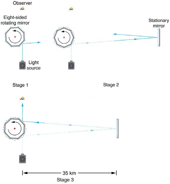
particularly direct method, used in 1887 by the American physicist Albert Michelson (1852–1931), is illustrated in Figure 25.11. Light reflected from a
rotating set of mirrors was reflected from a stationary mirror 35 km away and returned to the rotating mirrors. The time for the light to travel can be
determined by how fast the mirrors must rotate for the light to be returned to the observer’s eye.
CHAPTER 25 | GEOMETRIC OPTICS 893
Figure 25.11 A schematic of early apparatus used by Michelson and others to determine the speed of light. As the mirrors rotate, the reflected ray is only briefly directed at the stationary mirror. The returning ray will be reflected into the observer's eye only if the next mirror has rotated into the correct position just as the ray returns. By measuring the
correct rotation rate, the time for the round trip can be measured and the speed of light calculated. Michelson’s calculated value of the speed of light was only 0.04% different
from the value used today.
The speed of light is now known to great precision. In fact, the speed of light in a vacuum c is so important that it is accepted as one of the basic
physical quantities and has the fixed value
(25.1)
c = 2.9972458×10⁸ m/s ≈ 3.00×10⁸ m/s,
where the approximate value of 3.00×10⁸ m/s is used whenever three-digit accuracy is sufficient. The speed of light through matter is less than it
is in a vacuum, because light interacts with atoms in a material. The speed of light depends strongly on the type of material, since its interaction with
different atoms, crystal lattices, and other substructures varies. We define the index of refraction n of a material to be
(25.2)
n = cv,
where v is the observed speed of light in the material. Since the speed of light is always less than c in matter and equals c only in a vacuum, the
index of refraction is always greater than or equal to one.
Value of the Speed of Light
(25.3)
c = 2.9972458×10⁸ m/s ≈ 3.00×10⁸ m/s
Index of Refraction
(25.4)
n = cv
That is, n ≥ 1 . Table 25.1 gives the indices of refraction for some representative substances. The values are listed for a particular wavelength of light, because they vary slightly with wavelength. (This can have important effects, such as colors produced by a prism.) Note that for gases, n is
close to 1.0. This seems reasonable, since atoms in gases are widely separated and light travels at c in the vacuum between atoms. It is common to
take n = 1 for gases unless great precision is needed. Although the speed of light v in a medium varies considerably from its value c in a
vacuum, it is still a large speed.
894 CHAPTER 25 | GEOMETRIC OPTICS
Table 25.1 Index of Refraction
in Various Media
Medium
n
Gases at 0ºC , 1 atm
Air
1.000293
Carbon dioxide
1.00045
Hydrogen
1.000139
Oxygen
1.000271
Liquids at 20ºC
Benzene
1.501
Carbon disulfide
1.628
Carbon tetrachloride 1.461
Ethanol
1.361
Glycerine
1.473
Water, fresh
1.333
Solids at 20ºC
Diamond
2.419
Fluorite
1.434
Glass, crown
1.52
Glass, flint
1.66
Ice at 20ºC
1.309
Polystyrene
1.49
Plexiglas
1.51
Quartz, crystalline
1.544
Quartz, fused
1.458
Sodium chloride
1.544
Zircon
1.923
Example 25.1 Speed of Light in Matter
Calculate the speed of light in zircon, a material used in jewelry to imitate diamond.
Strategy
The speed of light in a material, v , can be calculated from the index of refraction n of the material using the equation n = c / v .
Solution
The equation for index of refraction states that n = c / v . Rearranging this to determine v gives
(25.5)
v = cn.
The index of refraction for zircon is given as 1.923 in Table 25.1, and c is given in the equation for speed of light. Entering these values in the last expression gives
(25.6)
v = 3.00×10⁸ m/s
1.923
= 1.56×10⁸ m/s.
Discussion
This speed is slightly larger than half the speed of light in a vacuum and is still high compared with speeds we normally experience. The only
substance listed in Table 25.1 that has a greater index of refraction than zircon is diamond. We shall see later that the large index of refraction for zircon makes it sparkle more than glass, but less than diamond.
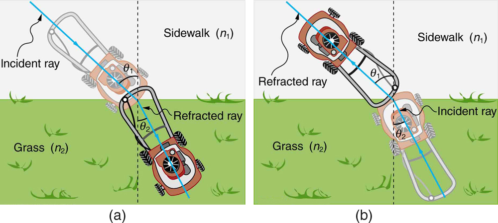
Law of Refraction
Figure 25.12 shows how a ray of light changes direction when it passes from one medium to another. As before, the angles are measured relative to
a perpendicular to the surface at the point where the light ray crosses it. (Some of the incident light will be reflected from the surface, but for now we
will concentrate on the light that is transmitted.) The change in direction of the light ray depends on how the speed of light changes. The change in
CHAPTER 25 | GEOMETRIC OPTICS 895
the speed of light is related to the indices of refraction of the media involved. In the situations shown in Figure 25.12, medium 2 has a greater index
of refraction than medium 1. This means that the speed of light is less in medium 2 than in medium 1. Note that as shown in Figure 25.12(a), the
direction of the ray moves closer to the perpendicular when it slows down. Conversely, as shown in Figure 25.12(b), the direction of the ray moves
away from the perpendicular when it speeds up. The path is exactly reversible. In both cases, you can imagine what happens by thinking about
pushing a lawn mower from a footpath onto grass, and vice versa. Going from the footpath to grass, the front wheels are slowed and pulled to the
side as shown. This is the same change in direction as for light when it goes from a fast medium to a slow one. When going from the grass to the
footpath, the front wheels can move faster and the mower changes direction as shown. This, too, is the same change in direction as for light going
from slow to fast.
Figure 25.12 The change in direction of a light ray depends on how the speed of light changes when it crosses from one medium to another. The speed of light is greater in
medium 1 than in medium 2 in the situations shown here. (a) A ray of light moves closer to the perpendicular when it slows down. This is analogous to what happens when a
lawn mower goes from a footpath to grass. (b) A ray of light moves away from the perpendicular when it speeds up. This is analogous to what happens when a lawn mower
goes from grass to footpath. The paths are exactly reversible.
The amount that a light ray changes its direction depends both on the incident angle and the amount that the speed changes. For a ray at a given
incident angle, a large change in speed causes a large change in direction, and thus a large change in angle. The exact mathematical relationship is
the law of refraction, or “Snell’s Law,” which is stated in equation form as
n
(25.7)
1 sin θ 1 = n 2 sin θ 2.
Here n 1 and n 2 are the indices of refraction for medium 1 and 2, and θ 1 and θ 2 are the angles between the rays and the perpendicular in
medium 1 and 2, as shown in Figure 25.12. The incoming ray is called the incident ray and the outgoing ray the refracted ray, and the associated
angles the incident angle and the refracted angle. The law of refraction is also called Snell’s law after the Dutch mathematician Willebrord Snell
(1591–1626), who discovered it in 1621. Snell’s experiments showed that the law of refraction was obeyed and that a characteristic index of
refraction n could be assigned to a given medium. Snell was not aware that the speed of light varied in different media, but through experiments he
was able to determine indices of refraction from the way light rays changed direction.
The Law of Refraction
n
(25.8)
1 sin θ 1 = n 2 sin θ 2
Take-Home Experiment: A Broken Pencil
A classic observation of refraction occurs when a pencil is placed in a glass half filled with water. Do this and observe the shape of the pencil
when you look at the pencil sideways, that is, through air, glass, water. Explain your observations. Draw ray diagrams for the situation.
Example 25.2 Determine the Index of Refraction from Refraction Data
Find the index of refraction for medium 2 in Figure 25.12(a), assuming medium 1 is air and given the incident angle is 30.0º and the angle of
refraction is 22.0º .
Strategy
The index of refraction for air is taken to be 1 in most cases (and up to four significant figures, it is 1.000). Thus n 1 = 1.00 here. From the given
information, θ 1 = 30.0º and θ 2 = 22.0º . With this information, the only unknown in Snell’s law is n 2 , so that it can be used to find this
unknown.
Solution
Snell’s law is
n
(25.9)
1 sin θ 1 = n 2 sin θ 2.
Rearranging to isolate n 2 gives
(25.10)
n
sin θ 1
2 = n 1sin θ .2
896 CHAPTER 25 | GEOMETRIC OPTICS
Entering known values,
(25.11)
n 2 = 1.00sin 30.0º
sin 22.0º = 0.500
0.375
= 1.33.
Discussion
This is the index of refraction for water, and Snell could have determined it by measuring the angles and performing this calculation. He would
then have found 1.33 to be the appropriate index of refraction for water in all other situations, such as when a ray passes from water to glass.
Today we can verify that the index of refraction is related to the speed of light in a medium by measuring that speed directly.
Example 25.3 A Larger Change in Direction
Suppose that in a situation like that in Example 25.2, light goes from air to diamond and that the incident angle is 30.0º . Calculate the angle of refraction θ 2 in the diamond.
Strategy
Again the index of refraction for air is taken to be n 1 = 1.00 , and we are given θ 1 = 30.0º . We can look up the index of refraction for
diamond in Table 25.1, finding n 2 = 2.419 . The only unknown in Snell’s law is θ 2 , which we wish to determine.
Solution
Solving Snell’s law for sin θ 2 yields
(25.12)
sin θ 2 = n 1
n sin θ
2
1.
Entering known values,
(25.13)
sin θ 2 = 1.00
2.419sin 30.0º=⎛⎝0.413⎞⎠(0.500) = 0.207.
The angle is thus
(25.14)
θ 2 = sin−10.207 = 11.9º.
Discussion
For the same 30º angle of incidence, the angle of refraction in diamond is significantly smaller than in water ( 11.9º rather than 22º —see the
preceding example). This means there is a larger change in direction in diamond. The cause of a large change in direction is a large change in
the index of refraction (or speed). In general, the larger the change in speed, the greater the effect on the direction of the ray.
25.4 Total Internal Reflection
A good-quality mirror may reflect more than 90% of the light that falls on it, absorbing the rest. But it would be useful to have a mirror that reflects all
of the light that falls on it. Interestingly, we can produce total reflection using an aspect of refraction.
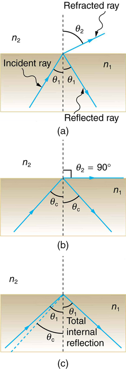
Consider what happens when a ray of light strikes the surface between two materials, such as is shown in Figure 25.13(a). Part of the light crosses
the boundary and is refracted; the rest is reflected. If, as shown in the figure, the index of refraction for the second medium is less than for the first,
the ray bends away from the perpendicular. (Since n1 > n2 , the angle of refraction is greater than the angle of incidence—that is, θ1 > θ2 .) Now
imagine what happens as the incident angle is increased. This causes θ2 to increase also. The largest the angle of refraction θ2 can be is 90º , as
shown in Figure 25.13(b).The critical angle θc for a combination of materials is defined to be the incident angle θ 1 that produces an angle of refraction of 90º . That is, θc is the incident angle for which θ2 = 90º . If the incident angle θ 1 is greater than the critical angle, as shown in
Figure 25.13(c), then all of the light is reflected back into medium 1, a condition called total internal reflection.
Critical Angle
The incident angle θ 1 that produces an angle of refraction of 90º is called the critical angle, θ c .
CHAPTER 25 | GEOMETRIC OPTICS 897
Figure 25.13 (a) A ray of light crosses a boundary where the speed of light increases and the index of refraction decreases. That is, n2 < n1 . The ray bends away from the perpendicular. (b) The critical angle θc is the one for which the angle of refraction is . (c) Total internal reflection occurs when the incident angle is greater than the critical angle.
Snell’s law states the relationship between angles and indices of refraction. It is given by
n
(25.15)
1 sin θ 1 = n 2 sin θ 2.
When the incident angle equals the critical angle ( θ 1 = θc ), the angle of refraction is 90º ( θ 2 = 90º ). Noting that sin 90º=1 , Snell’s law in this case becomes
n
(25.16)
1 sin θ 1 = n 2.
The critical angle θc for a given combination of materials is thus
⎞
(25.17)
θc = sin−1⎛⎝ n 2 / n 1⎠ for n 1 > n 2.
Total internal reflection occurs for any incident angle greater than the critical angle θc , and it can only occur when the second medium has an index
of refraction less than the first. Note the above equation is written for a light ray that travels in medium 1 and reflects from medium 2, as shown in the
figure.
Example 25.4 How Big is the Critical Angle Here?
What is the critical angle for light traveling in a polystyrene (a type of plastic) pipe surrounded by air?
Strategy
898 CHAPTER 25 | GEOMETRIC OPTICS
The index of refraction for polystyrene is found to be 1.49 in Figure 25.14, and the index of refraction of air can be taken to be 1.00, as before.
Thus, the condition that the second medium (air) has an index of refraction less than the first (plastic) is satisfied, and the equation
θc = sin−1⎛
⎞
⎝ n 2 / n 1⎠ can be used to find the critical angle θc . Here, then, n 2 = 1.00 and n 1 = 1.49 .
Solution
The critical angle is given by
⎞
(25.18)
θc = sin−1⎛⎝ n 2 / n 1⎠.
Substituting the identified values gives
(25.19)
θc = sin−1(1.00 / 1.49) = sin−1(0.671)
42.2º.
Discussion
This means that any ray of light inside the plastic that strikes the surface at an angle greater than 42.2º will be totally reflected. This will make
the inside surface of the clear plastic a perfect mirror for such rays without any need for the silvering used on common mirrors. Different
combinations of materials have different critical angles, but any combination with n1 > n2 can produce total internal reflection. The same
calculation as made here shows that the critical angle for a ray going from water to air is 48.6º , while that from diamond to air is 24.4º , and
that from flint glass to crown glass is 66.3º . There is no total reflection for rays going in the other direction—for example, from air to
water—since the condition that the second medium must have a smaller index of refraction is not satisfied. A number of interesting applications
of total internal reflection follow.
Fiber Optics: Endoscopes to Telephones
Fiber optics is one application of total internal reflection that is in wide use. In communications, it is used to transmit telephone, internet, and cable TV
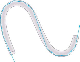
signals. Fiber optics employs the transmission of light down fibers of plastic or glass. Because the fibers are thin, light entering one is likely to strike
the inside surface at an angle greater than the critical angle and, thus, be totally reflected (See Figure 25.14.) The index of refraction outside the fiber
must be smaller than inside, a condition that is easily satisfied by coating the outside of the fiber with a material having an appropriate refractive
index. In fact, most fibers have a varying refractive index to allow more light to be guided along the fiber through total internal refraction. Rays are
reflected around corners as shown, making the fibers into tiny light pipes.
Figure 25.14 Light entering a thin fiber may strike the inside surface at large or grazing angles and is completely reflected if these angles exceed the critical angle. Such rays continue down the fiber, even following it around corners, since the angles of reflection and incidence remain large.
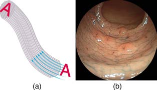
Bundles of fibers can be used to transmit an image without a lens, as illustrated in Figure 25.15. The output of a device called an endoscope is shown in Figure 25.15(b). Endoscopes are used to explore the body through various orifices or minor incisions. Light is transmitted down one fiber
bundle to illuminate internal parts, and the reflected light is transmitted back out through another to be observed. Surgery can be performed, such as
arthroscopic surgery on the knee joint, employing cutting tools attached to and observed with the endoscope. Samples can also be obtained, such as
by lassoing an intestinal polyp for external examination.
Fiber optics has revolutionized surgical techniques and observations within the body. There are a host of medical diagnostic and therapeutic uses.
The flexibility of the fiber optic bundle allows it to navigate around difficult and small regions in the body, such as the intestines, the heart, blood
vessels, and joints. Transmission of an intense laser beam to burn away obstructing plaques in major arteries as well as delivering light to activate
chemotherapy drugs are becoming commonplace. Optical fibers have in fact enabled microsurgery and remote surgery where the incisions are small
and the surgeon’s fingers do not need to touch the diseased tissue.
Figure 25.15 (a) An image is transmitted by a bundle of fibers that have fixed neighbors. (b) An endoscope is used to probe the body, both transmitting light to the interior and returning an image such as the one shown. (credit: Med_Chaos, Wikimedia Commons)
CHAPTER 25 | GEOMETRIC OPTICS 899
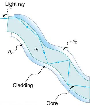
Fibers in bundles are surrounded by a cladding material that has a lower index of refraction than the core. (See Figure 25.16.) The cladding prevents
light from being transmitted between fibers in a bundle. Without cladding, light could pass between fibers in contact, since their indices of refraction
are identical. Since no light gets into the cladding (there is total internal reflection back into the core), none can be transmitted between clad fibers
that are in contact with one another. The cladding prevents light from escaping out of the fiber; instead most of the light is propagated along the
length of the fiber, minimizing the loss of signal and ensuring that a quality image is formed at the other end. The cladding and an additional
protective layer make optical fibers flexible and durable.
Figure 25.16 Fibers in bundles are clad by a material that has a lower index of refraction than the core to ensure total internal reflection, even when fibers are in contact with one another. This shows a single fiber with its cladding.
Cladding
The cladding prevents light from being transmitted between fibers in a bundle.
Special tiny lenses that can be attached to the ends of bundles of fibers are being designed and fabricated. Light emerging from a fiber bundle can be
focused and a tiny spot can be imaged. In some cases the spot can be scanned, allowing quality imaging of a region inside the body. Special minute
optical filters inserted at the end of the fiber bundle have the capacity to image tens of microns below the surface without cutting the surface—non-
intrusive diagnostics. This is particularly useful for determining the extent of cancers in the stomach and bowel.
Most telephone conversations and Internet communications are now carried by laser signals along optical fibers. Extensive optical fiber cables have
been placed on the ocean floor and underground to enable optical communications. Optical fiber communication systems offer several advantages
over electrical (copper) based systems, particularly for long distances. The fibers can be made so transparent that light can travel many kilometers
Describe what you're looking for in as much detail as you'd like.
Our AI reads your request and finds the best matching books for you.
Popular searches:
Join 2.9 million readers and get unlimited free ebooks