Solution for (a)
846 CHAPTER 23 | ELECTROMAGNETIC INDUCTION, AC CIRCUITS, AND ELECTRICAL TECHNOLOGIES
At 60.0 Hz, the values of the reactances were found in Example 23.10 to be XL = 1.13 Ω and in Example 23.11 to be XC = 531 Ω .
Entering these and the given 40.0 Ω for resistance into Z = R 2 + ( XL − XC)2 yields
(23.67)
Z = R 2 + ( XL − XC)2
= (40.0 Ω )2 + (1.13 Ω − 531 Ω )2
= 531 Ω at 60.0 Hz.
Similarly, at 10.0 kHz, XL = 188 Ω and XC = 3.18 Ω , so that
(23.68)
Z = (40.0 Ω )2 + (188 Ω − 3.18 Ω )2
= 190 Ω at 10.0 kHz.
Discussion for (a)
In both cases, the result is nearly the same as the largest value, and the impedance is definitely not the sum of the individual values. It is clear
that XL dominates at high frequency and XC dominates at low frequency.
Solution for (b)
The current I rms can be found using the AC version of Ohm’s law in Equation I rms = V rms / Z :
I rms = V rms
Z = 120 V
531 Ω = 0.226 A at 60.0 Hz
Finally, at 10.0 kHz, we find
I rms = V rms
Z = 120 V
190 Ω = 0.633 A at 10.0 kHz
Discussion for (a)
The current at 60.0 Hz is the same (to three digits) as found for the capacitor alone in Example 23.11. The capacitor dominates at low frequency.
The current at 10.0 kHz is only slightly different from that found for the inductor alone in Example 23.10. The inductor dominates at high
frequency.
Resonance in RLC Series AC Circuits
How does an RLC circuit behave as a function of the frequency of the driving voltage source? Combining Ohm’s law, I rms = V rms / Z , and the
expression for impedance Z from Z = R 2 + ( XL − XC)2 gives
(23.69)
I rms =
V rms
.
R 2 + ( XL − XC)2
The reactances vary with frequency, with XL large at high frequencies and XC large at low frequencies, as we have seen in three previous
examples. At some intermediate frequency f 0 , the reactances will be equal and cancel, giving Z = R —this is a minimum value for impedance,
and a maximum value for I rms results. We can get an expression for f 0 by taking
X
(23.70)
L = XC.
Substituting the definitions of XL and XC ,
(23.71)
2 πf 0 L = 1
2 πf 0 C.
Solving this expression for f 0 yields
(23.72)
f 0 = 1 ,
2π LC
where f 0 is the resonant frequency of an RLC series circuit. This is also the natural frequency at which the circuit would oscillate if not driven by the voltage source. At f 0 , the effects of the inductor and capacitor cancel, so that Z = R , and I rms is a maximum.
Resonance in AC circuits is analogous to mechanical resonance, where resonance is defined to be a forced oscillation—in this case, forced by the
voltage source—at the natural frequency of the system. The receiver in a radio is an RLC circuit that oscillates best at its f 0 . A variable capacitor is
often used to adjust f 0 to receive a desired frequency and to reject others. Figure 23.50 is a graph of current as a function of frequency, illustrating a resonant peak in I rms at f 0 . The two curves are for two different circuits, which differ only in the amount of resistance in them. The peak is lower
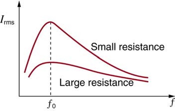
CHAPTER 23 | ELECTROMAGNETIC INDUCTION, AC CIRCUITS, AND ELECTRICAL TECHNOLOGIES 847
and broader for the higher-resistance circuit. Thus the higher-resistance circuit does not resonate as strongly and would not be as selective in a radio
receiver, for example.
Figure 23.50 A graph of current versus frequency for two RLC series circuits differing only in the amount of resistance. Both have a resonance at f 0 , but that for the higher resistance is lower and broader. The driving AC voltage source has a fixed amplitude V 0 .
Example 23.13 Calculating Resonant Frequency and Current
For the same RLC series circuit having a 40.0 Ω resistor, a 3.00 mH inductor, and a 5.00 μF capacitor: (a) Find the resonant frequency. (b)
Calculate I rms at resonance if V rms is 120 V.
Strategy
The resonant frequency is found by using the expression in f 0 =
1
2π
. The current at that frequency is the same as if the resistor alone
LC
were in the circuit.
Solution for (a)
Entering the given values for L and C into the expression given for f 0 in f 0 =
1
2π
yields
LC
(23.73)
f 0 =
1
2π LC
=
1
= 1.30 kHz.
2π (3.00×10⁻³ H)(5.00×10⁻⁶ F)
Discussion for (a)
We see that the resonant frequency is between 60.0 Hz and 10.0 kHz, the two frequencies chosen in earlier examples. This was to be expected,
since the capacitor dominated at the low frequency and the inductor dominated at the high frequency. Their effects are the same at this
intermediate frequency.
Solution for (b)
The current is given by Ohm’s law. At resonance, the two reactances are equal and cancel, so that the impedance equals the resistance alone.
Thus,
(23.74)
I rms = V rms
Z = 120 V
40.0 Ω = 3.00 A.
Discussion for (b)
At resonance, the current is greater than at the higher and lower frequencies considered for the same circuit in the preceding example.
Power in RLC Series AC Circuits
If current varies with frequency in an RLC circuit, then the power delivered to it also varies with frequency. But the average power is not simply
current times voltage, as it is in purely resistive circuits. As was seen in Figure 23.49, voltage and current are out of phase in an RLC circuit. There is a phase angle ϕ between the source voltage V and the current I , which can be found from
(23.75)
cos ϕ = RZ.
For example, at the resonant frequency or in a purely resistive circuit Z = R , so that cos ϕ = 1 . This implies that ϕ = 0 º and that voltage and
current are in phase, as expected for resistors. At other frequencies, average power is less than at resonance. This is both because voltage and
current are out of phase and because I rms is lower. The fact that source voltage and current are out of phase affects the power delivered to the
circuit. It can be shown that the average power is
P
(23.76)
ave = I rms V rms cos ϕ,
848 CHAPTER 23 | ELECTROMAGNETIC INDUCTION, AC CIRCUITS, AND ELECTRICAL TECHNOLOGIES
Thus cos ϕ is called the power factor, which can range from 0 to 1. Power factors near 1 are desirable when designing an efficient motor, for
example. At the resonant frequency, cos ϕ = 1 .
Example 23.14 Calculating the Power Factor and Power
For the same RLC series circuit having a 40.0 Ω resistor, a 3.00 mH inductor, a 5.00 μF capacitor, and a voltage source with a V rms of 120
V: (a) Calculate the power factor and phase angle for f = 60.0Hz . (b) What is the average power at 50.0 Hz? (c) Find the average power at
the circuit’s resonant frequency.
Strategy and Solution for (a)
The power factor at 60.0 Hz is found from
(23.77)
cos ϕ = RZ.
We know Z= 531 Ω from Example 23.12, so that
(23.78)
cos ϕ = 40.0 Ω
531 Ω = 0.0753 at 60.0 Hz.
This small value indicates the voltage and current are significantly out of phase. In fact, the phase angle is
(23.79)
ϕ = cos−1 0.0753 = 85.7º at 60.0 Hz.
Discussion for (a)
The phase angle is close to 90º , consistent with the fact that the capacitor dominates the circuit at this low frequency (a pure RC circuit has its
voltage and current 90º out of phase).
Strategy and Solution for (b)
The average power at 60.0 Hz is
P
(23.80)
ave = I rms V rms cos ϕ.
I rms was found to be 0.226 A in Example 23.12. Entering the known values gives
P
(23.81)
ave = (0.226 A)(120 V)(0.0753) = 2.04 W at 60.0 Hz.
Strategy and Solution for (c)
At the resonant frequency, we know cos ϕ = 1 , and I rms was found to be 6.00 A in Example 23.13. Thus,
P ave = (3.00 A)(120 V)(1) = 360 W at resonance (1.30 kHz)
Discussion
Both the current and the power factor are greater at resonance, producing significantly greater power than at higher and lower frequencies.
Power delivered to an RLC series AC circuit is dissipated by the resistance alone. The inductor and capacitor have energy input and output but do
not dissipate it out of the circuit. Rather they transfer energy back and forth to one another, with the resistor dissipating exactly what the voltage
source puts into the circuit. This assumes no significant electromagnetic radiation from the inductor and capacitor, such as radio waves. Such
radiation can happen and may even be desired, as we will see in the next chapter on electromagnetic radiation, but it can also be suppressed as is
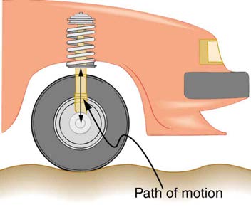
the case in this chapter. The circuit is analogous to the wheel of a car driven over a corrugated road as shown in Figure 23.51. The regularly spaced
bumps in the road are analogous to the voltage source, driving the wheel up and down. The shock absorber is analogous to the resistance damping
and limiting the amplitude of the oscillation. Energy within the system goes back and forth between kinetic (analogous to maximum current, and
energy stored in an inductor) and potential energy stored in the car spring (analogous to no current, and energy stored in the electric field of a
capacitor). The amplitude of the wheels’ motion is a maximum if the bumps in the road are hit at the resonant frequency.
CHAPTER 23 | ELECTROMAGNETIC INDUCTION, AC CIRCUITS, AND ELECTRICAL TECHNOLOGIES 849
Figure 23.51 The forced but damped motion of the wheel on the car spring is analogous to an RLC series AC circuit. The shock absorber damps the motion and dissipates
energy, analogous to the resistance in an RLC circuit. The mass and spring determine the resonant frequency.
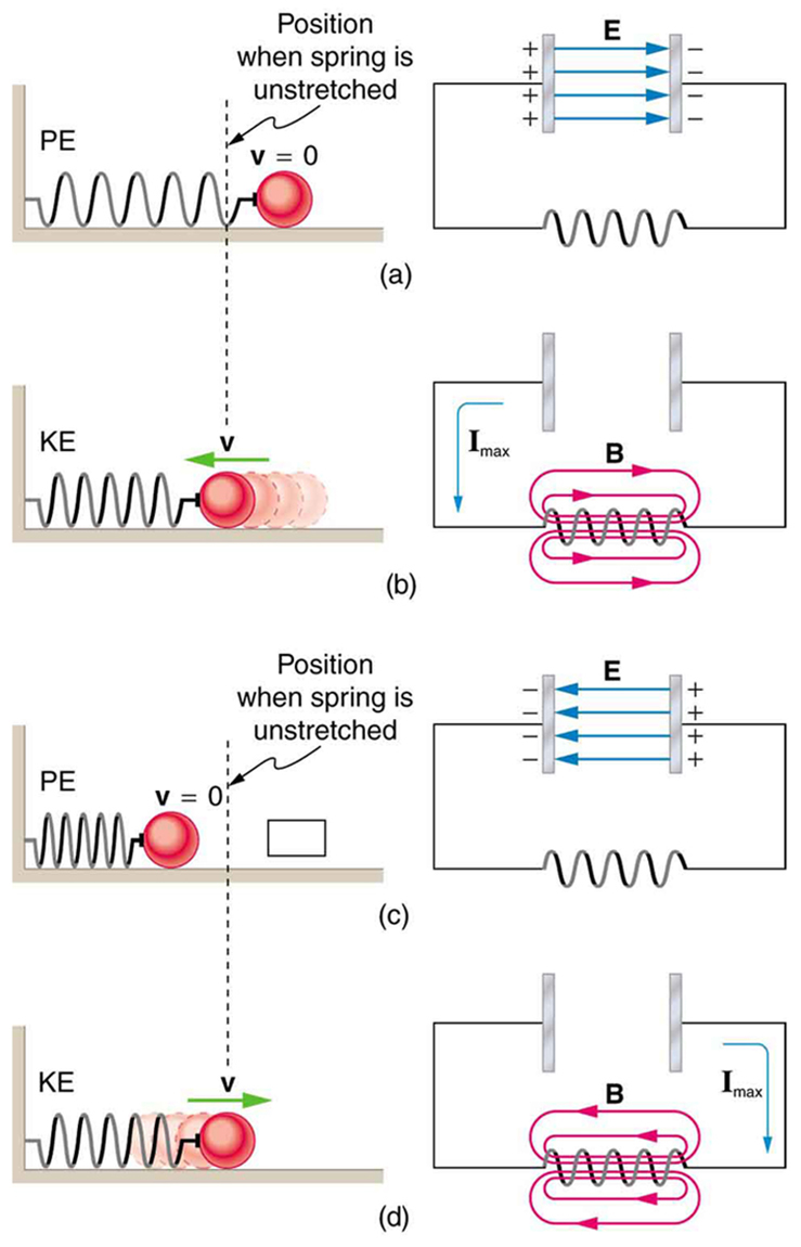
A pure LC circuit with negligible resistance oscillates at f 0 , the same resonant frequency as an RLC circuit. It can serve as a frequency standard or
clock circuit—for example, in a digital wristwatch. With a very small resistance, only a very small energy input is necessary to maintain the
oscillations. The circuit is analogous to a car with no shock absorbers. Once it starts oscillating, it continues at its natural frequency for some time.
Figure 23.52 shows the analogy between an LC circuit and a mass on a spring.
Figure 23.52 An LC circuit is analogous to a mass oscillating on a spring with no friction and no driving force. Energy moves back and forth between the inductor and
capacitor, just as it moves from kinetic to potential in the mass-spring system.
PhET Explorations: Circuit Construction Kit (AC+DC), Virtual Lab
Build circuits with capacitors, inductors, resistors and AC or DC voltage sources, and inspect them using lab instruments such as voltmeters and
ammeters.

850 CHAPTER 23 | ELECTROMAGNETIC INDUCTION, AC CIRCUITS, AND ELECTRICAL TECHNOLOGIES
Glossary
back emf: the emf generated by a running motor, because it consists of a coil turning in a magnetic field; it opposes the voltage powering the
motor
capacitive reactance: the opposition of a capacitor to a change in current; calculated by XC = 1
2π fC
characteristic time constant: denoted by τ , of a particular series RL circuit is calculated by τ = LR , where L is the inductance and R is the resistance
eddy current: a current loop in a conductor caused by motional emf
electric generator: a device for converting mechanical work into electric energy; it induces an emf by rotating a coil in a magnetic field
electromagnetic induction: the process of inducing an emf (voltage) with a change in magnetic flux
emf induced in a generator coil: emf = NABω sin ωt , where A is the area of an N -turn coil rotated at a constant angular velocity ω in a uniform magnetic field B , over a period of time t
energy stored in an inductor: self-explanatory; calculated by E ind = 12 LI 2
Faraday’s law of induction: the means of calculating the emf in a coil due to changing magnetic flux, given by emf = − NΔΦ
Δt
henry: the unit of inductance; 1 H = 1 Ω ⋅ s
impedance: the AC analogue to resistance in a DC circuit; it is the combined effect of resistance, inductive reactance, and capacitive reactance in
the form Z = R 2 + ( XL − XC)2
inductance: a property of a device describing how efficient it is at inducing emf in another device
induction: (magnetic induction) the creation of emfs and hence currents by magnetic fields
inductive reactance: the opposition of an inductor to a change in current; calculated by XL = 2π fL
inductor: a device that exhibits significant self-inductance
Lenz’s law: the minus sign in Faraday’s law, signifying that the emf induced in a coil opposes the change in magnetic flux
magnetic damping: the drag produced by eddy currents
magnetic flux: the amount of magnetic field going through a particular area, calculated with Φ = BA cos θ where B is the magnetic field
strength over an area A at an angle θ with the perpendicular to the area
mutual inductance: how effective a pair of devices are at inducing emfs in each other
peak emf: emf0 = NABω
phase angle: denoted by ϕ , the amount by which the voltage and current are out of phase with each other in a circuit
power factor: the amount by which the power delivered in the circuit is less than the theoretical maximum of the circuit due to voltage and current
being out of phase; calculated by cos ϕ
resonant frequency: the frequency at which the impedance in a circuit is at a minimum, and also the frequency at which the circuit would oscillate
if not driven by a voltage source; calculated by f 0 =
1
2π LC
self-inductance: how effective a device is at inducing emf in itself
CHAPTER 23 | ELECTROMAGNETIC INDUCTION, AC CIRCUITS, AND ELECTRICAL TECHNOLOGIES 851
shock hazard: the term for electrical hazards due to current passing through a human
step-down transformer: a transformer that decreases voltage
step-up transformer: a transformer that increases voltage
thermal hazard: the term for electrical hazards due to overheating
three-wire system: the wiring system used at present for safety reasons, with live, neutral, and ground wires
transformer equation: the equation showing that the ratio of the secondary to primary voltages in a transformer equals the ratio of the number of
V
loops in their coils;
s
V = N s
p
N p
transformer: a device that transforms voltages from one value to another using induction
Section Summary
23.1 Induced Emf and Magnetic Flux
• The crucial quantity in induction is magnetic flux Φ , defined to be Φ = BA cos θ , where B is the magnetic field strength over an area A at an angle θ with the perpendicular to the area.
• Units of magnetic flux Φ are T ⋅ m2 .
• Any change in magnetic flux Φ induces an emf—the process is defined to be electromagnetic induction.
23.2 Faraday’s Law of Induction: Lenz’s Law
• Faraday’s law of induction states that the emfinduced by a change in magnetic flux is
emf = − NΔ Φ
Δ t
when flux changes by Δ Φ in a time Δ t .
• If emf is induced in a coil, N is its number of turns.
• The minus sign means that the emf creates a current I and magnetic field B that oppose the change in flux Δ Φ —this opposition is known
as Lenz’s law.
• An emf induced by motion relative to a magnetic field B is called a motional emf and is given by
emf = Bℓv
( B, ℓ, and v perpendicular),
where ℓ is the length of the object moving at speed v relative to the field.
23.4 Eddy Currents and Magnetic Damping
• Current loops induced in moving conductors are called eddy currents.
• They can create significant drag, called magnetic damping.
• An electric generator rotates a coil in a magnetic field, inducing an emfgiven as a function of time by
emf = NABω sin ωt,
where A is the area of an N -turn coil rotated at a constant angular velocity ω in a uniform magnetic field B .
• The peak emf emf0 of a generator is
emf0 = NABω.
• Any rotating coil will have an induced emf—in motors, this is called back emf, since it opposes the emf input to the motor.
• Transformers use induction to transform voltages from one value to another.
• For a transformer, the voltages across the primary and secondary coils are related by
V s
V = N s,
p
N p
where V p and V s are the voltages across primary and secondary coils having N p and N s turns.
I
N p
• The currents I p and I s in the primary and secondary coils are related by s
I =
.
p
N s
• A step-up transformer increases voltage and decreases current, whereas a step-down transformer decreases voltage and increases current.
23.8 Electrical Safety: Systems and Devices
• Electrical safety systems and devices are employed to prevent thermal and shock hazards.
852 CHAPTER 23 | ELECTROMAGNETIC INDUCTION, AC CIRCUITS, AND ELECTRICAL TECHNOLOGIES
• Circuit breakers and fuses interrupt excessive currents to prevent thermal hazards.
• The three-wire system guards against thermal and shock hazards, utilizing live/hot, neutral, and earth/ground wires, and grounding the neutral
wire and case of the appliance.
• A ground fault interrupter (GFI) prevents shock by detecting the loss of current to unintentional paths.
• An isolation transformer insulates the device being powered from the original source, also to prevent shock.
• Many of these devices use induction to perform their basic function.
• Inductance is the property of a device that tells how effectively it induces an emf in another device.
• Mutual inductance is the effect of two devices in inducing emfs in each other.
• A change in current Δ I 1 / Δ t in one induces an emf emf2 in the second:
emf2 = − MΔ I 1
<Describe what you're looking for in as much detail as you'd like.
Our AI reads your request and finds the best matching books for you.
Popular searches:
Join 2.9 million readers and get unlimited free ebooks