834 CHAPTER 23 | ELECTROMAGNETIC INDUCTION, AC CIRCUITS, AND ELECTRICAL TECHNOLOGIES
Figure 23.34 Worn insulation allows the live/hot wire to come into direct contact with the metal case of this appliance. (a) The earth/ground connection being broken, the
person is severely shocked. The appliance may operate normally in this situation. (b) With a proper earth/ground, the circuit breaker trips, forcing repair of the appliance.
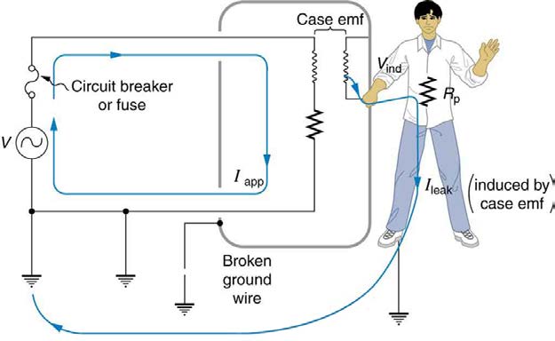
Electromagnetic induction causes a more subtle problem that is solved by grounding the case. The AC current in appliances can induce an emf on
the case. If grounded, the case voltage is kept near zero, but if the case is not grounded, a shock can occur as pictured in Figure 23.35. Current
driven by the induced case emf is called a leakage current, although current does not necessarily pass from the resistor to the case.
Figure 23.35 AC currents can induce an emf on the case of an appliance. The voltage can be large enough to cause a shock. If the case is grounded, the induced emf is kept
near zero.
CHAPTER 23 | ELECTROMAGNETIC INDUCTION, AC CIRCUITS, AND ELECTRICAL TECHNOLOGIES 835
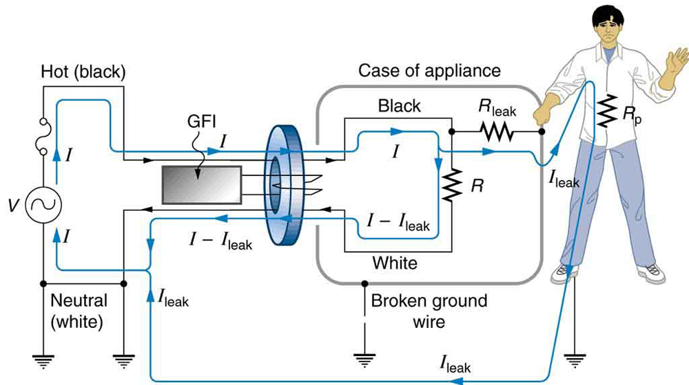
A ground fault interrupter (GFI) is a safety device found in updated kitchen and bathroom wiring that works based on electromagnetic induction. GFIs
compare the currents in the live/hot and neutral wires. When live/hot and neutral currents are not equal, it is almost always because current in the
neutral is less than in the live/hot wire. Then some of the current, again called a leakage current, is returning to the voltage source by a path other
than through the neutral wire. It is assumed that this path presents a hazard, such as shown in Figure 23.36. GFIs are usually set to interrupt the circuit if the leakage current is greater than 5 mA, the accepted maximum harmless shock. Even if the leakage current goes safely to earth/ground
through an intact earth/ground wire, the GFI will trip, forcing repair of the leakage.
Figure 23.36 A ground fault interrupter (GFI) compares the currents in the live/hot and neutral wires and will trip if their difference exceeds a safe value. The leakage current here follows a hazardous path that could have been prevented by an intact earth/ground wire.
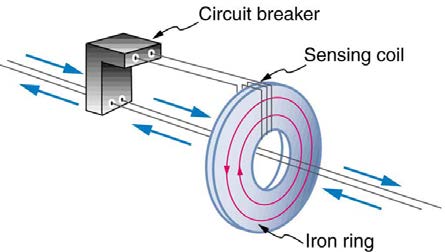
Figure 23.37 shows how a GFI works. If the currents in the live/hot and neutral wires are equal, then they induce equal and opposite emfs in the coil.
If not, then the circuit breaker will trip.
Figure 23.37 A GFI compares currents by using both to induce an emf in the same coil. If the currents are equal, they will induce equal but opposite emfs.
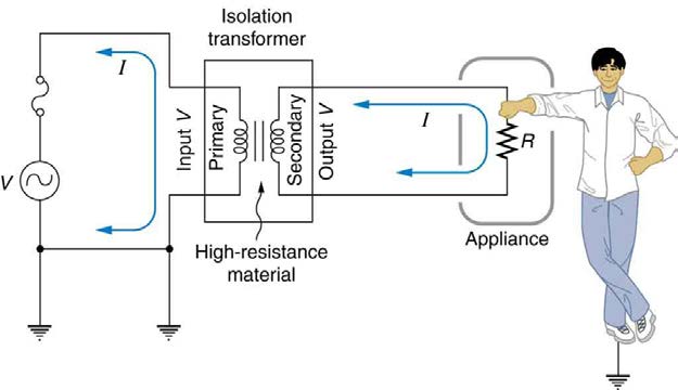
Another induction-based safety device is the isolation transformer, shown in Figure 23.38. Most isolation transformers have equal input and output voltages. Their function is to put a large resistance between the original voltage source and the device being operated. This prevents a complete
circuit between them, even in the circumstance shown. There is a complete circuit through the appliance. But there is not a complete circuit for
current to flow through the person in the figure, who is touching only one of the transformer’s output wires, and neither output wire is grounded. The
appliance is isolated from the original voltage source by the high resistance of the material between the transformer coils, hence the name isolation
transformer. For current to flow through the person, it must pass through the high-resistance material between the coils, through the wire, the person,
and back through the earth—a path with such a large resistance that the current is negligible.
Figure 23.38 An isolation transformer puts a large resistance between the original voltage source and the device, preventing a complete circuit between them.
836 CHAPTER 23 | ELECTROMAGNETIC INDUCTION, AC CIRCUITS, AND ELECTRICAL TECHNOLOGIES
The basics of electrical safety presented here help prevent many electrical hazards. Electrical safety can be pursued to greater depths. There are, for
example, problems related to different earth/ground connections for appliances in close proximity. Many other examples are found in hospitals.
Microshock-sensitive patients, for instance, require special protection. For these people, currents as low as 0.1 mA may cause ventricular fibrillation.
The interested reader can use the material presented here as a basis for further study.
23.9 Inductance
Inductors
Induction is the process in which an emf is induced by changing magnetic flux. Many examples have been discussed so far, some more effective than
others. Transformers, for example, are designed to be particularly effective at inducing a desired voltage and current with very little loss of energy to
other forms. Is there a useful physical quantity related to how “effective” a given device is? The answer is yes, and that physical quantity is called
inductance.
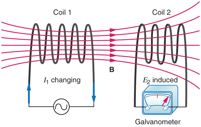
Mutual inductance is the effect of Faraday’s law of induction for one device upon another, such as the primary coil in transmitting energy to the
secondary in a transformer. See Figure 23.39, where simple coils induce emfs in one another.
Figure 23.39 These coils can induce emfs in one another like an inefficient transformer. Their mutual inductance M indicates the effectiveness of the coupling between them.
Here a change in current in coil 1 is seen to induce an emf in coil 2. (Note that " E 2 induced" represents the induced emf in coil 2.)
In the many cases where the geometry of the devices is fixed, flux is changed by varying current. We therefore concentrate on the rate of change of
current, Δ I/Δ t , as the cause of induction. A change in the current I 1 in one device, coil 1 in the figure, induces an emf2 in the other. We express
this in equation form as
(23.34)
emf2 = − MΔ I 1
Δ t ,
where M is defined to be the mutual inductance between the two devices. The minus sign is an expression of Lenz’s law. The larger the mutual
inductance M , the more effective the coupling. For example, the coils in Figure 23.39 have a small M compared with the transformer coils in
Figure 23.28. Units for M are (V ⋅ s)/A = Ω ⋅ s , which is named a henry (H), after Joseph Henry. That is, 1 H = 1 Ω ⋅ s .
Nature is symmetric here. If we change the current I 2 in coil 2, we induce an emf1 in coil 1, which is given by
(23.35)
emf1 = − MΔ I 2
Δ t ,
where M is the same as for the reverse process. Transformers run backward with the same effectiveness, or mutual inductance M .
A large mutual inductance M may or may not be desirable. We want a transformer to have a large mutual inductance. But an appliance, such as an
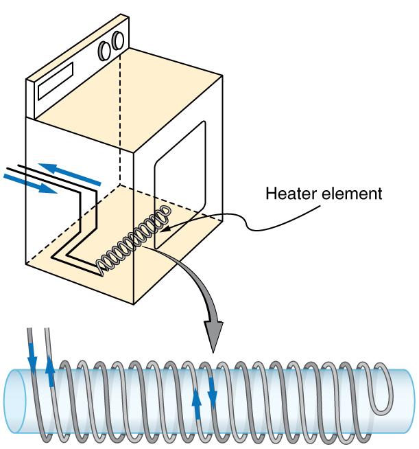
electric clothes dryer, can induce a dangerous emf on its case if the mutual inductance between its coils and the case is large. One way to reduce
mutual inductance M is to counterwind coils to cancel the magnetic field produced. (See Figure 23.40.)

CHAPTER 23 | ELECTROMAGNETIC INDUCTION, AC CIRCUITS, AND ELECTRICAL TECHNOLOGIES 837
Figure 23.40 The heating coils of an electric clothes dryer can be counter-wound so that their magnetic fields cancel one another, greatly reducing the mutual inductance with
the case of the dryer.
Self-inductance, the effect of Faraday’s law of induction of a device on itself, also exists. When, for example, current through a coil is increased, the
magnetic field and flux also increase, inducing a counter emf, as required by Lenz’s law. Conversely, if the current is decreased, an emf is induced
that opposes the decrease. Most devices have a fixed geometry, and so the change in flux is due entirely to the change in current Δ I through the
device. The induced emf is related to the physical geometry of the device and the rate of change of current. It is given by
(23.36)
emf = − LΔ I
Δ t,
where L is the self-inductance of the device. A device that exhibits significant self-inductance is called an inductor, and given the symbol in Figure
Figure 23.41
The minus sign is an expression of Lenz’s law, indicating that emf opposes the change in current. Units of self-inductance are henries (H) just as for
mutual inductance. The larger the self-inductance L of a device, the greater its opposition to any change in current through it. For example, a large
coil with many turns and an iron core has a large L and will not allow current to change quickly. To avoid this effect, a small L must be achieved,
such as by counterwinding coils as in Figure 23.40.
A 1 H inductor is a large inductor. To illustrate this, consider a device with L = 1.0 H that has a 10 A current flowing through it. What happens if we
try to shut off the current rapidly, perhaps in only 1.0 ms? An emf, given by emf = − L(Δ I / Δ t) , will oppose the change. Thus an emf will be
induced given by emf = − L(Δ I / Δ t) = (1.0 H)[(10 A) / (1.0 ms)] = 10,000 V . The positive sign means this large voltage is in the same
direction as the current, opposing its decrease. Such large emfs can cause arcs, damaging switching equipment, and so it may be necessary to
change current more slowly.
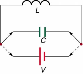
There are uses for such a large induced voltage. Camera flashes use a battery, two inductors that function as a transformer, and a switching system
or oscillator to induce large voltages. (Remember that we need a changing magnetic field, brought about by a changing current, to induce a voltage in
another coil.) The oscillator system will do this many times as the battery voltage is boosted to over one thousand volts. (You may hear the high
pitched whine from the transformer as the capacitor is being charged.) A capacitor stores the high voltage for later use in powering the flash. (See
838 CHAPTER 23 | ELECTROMAGNETIC INDUCTION, AC CIRCUITS, AND ELECTRICAL TECHNOLOGIES
Figure 23.42 Through rapid switching of an inductor, 1.5 V batteries can be used to induce emfs of several thousand volts. This voltage can be used to store charge in a
capacitor for later use, such as in a camera flash attachment.
It is possible to calculate L for an inductor given its geometry (size and shape) and knowing the magnetic field that it produces. This is difficult in
most cases, because of the complexity of the field created. So in this text the inductance L is usually a given quantity. One exception is the solenoid,
because it has a very uniform field inside, a nearly zero field outside, and a simple shape. It is instructive to derive an equation for its inductance. We
start by noting that the induced emf is given by Faraday’s law of induction as emf = − N(Δ Φ / Δ t) and, by the definition of self-inductance, as
emf = − L(Δ I / Δ t) . Equating these yields
(23.37)
emf = − NΔ Φ
Δ t = − LΔ I
Δ t.
Solving for L gives
(23.38)
L = NΔ Φ
Δ I .
This equation for the self-inductance L of a device is always valid. It means that self-inductance L depends on how effective the current is in
creating flux; the more effective, the greater Δ Φ / Δ I is.
Let us use this last equation to find an expression for the inductance of a solenoid. Since the area A of a solenoid is fixed, the change in flux is
Δ Φ = Δ( BA) = AΔ B . To find Δ B , we note that the magnetic field of a solenoid is given by B = µ
NI
0 nI = µ 0 ℓ . (Here n = N / ℓ , where N is
the number of coils and ℓ is the solenoid’s length.) Only the current changes, so that Δ Φ = AΔ B = µ 0 NAΔ I
ℓ . Substituting Δ Φ into
L = NΔ Φ
Δ I gives
(23.39)
µ
L = NΔ Φ
0 NAΔ I
ℓ
Δ I = N Δ I .
This simplifies to
(23.40)
L = µ 0 N 2 A
ℓ
(solenoid).
This is the self-inductance of a solenoid of cross-sectional area A and length ℓ . Note that the inductance depends only on the physical
characteristics of the solenoid, consistent with its definition.
Example 23.7 Calculating the Self-inductance of a Moderate Size Solenoid
Calculate the self-inductance of a 10.0 cm long, 4.00 cm diameter solenoid that has 200 coils.
Strategy
This is a straightforward application of L = µ 0 N 2 A
ℓ
, since all quantities in the equation except L are known.
Solution
Use the following expression for the self-inductance of a solenoid:
(23.41)
L = µ 0 N 2 A
ℓ
.
The cross-sectional area in this example is A = πr 2 = (3.14...)(0.0200 m)2 = 1.26×10⁻³ m2 , N is given to be 200, and the length ℓ is
0.100 m. We know the permeability of free space is µ 0 = 4π×10−7 T ⋅ m/A . Substituting these into the expression for L gives

CHAPTER 23 | ELECTROMAGNETIC INDUCTION, AC CIRCUITS, AND ELECTRICAL TECHNOLOGIES 839
(23.42)
L = (4π×10−7 T ⋅ m/A)(200)2(1.26×10−3 m2)
0.100 m
= 0.632 mH.
Discussion
This solenoid is moderate in size. Its inductance of nearly a millihenry is also considered moderate.
One common application of inductance is used in traffic lights that can tell when vehicles are waiting at the intersection. An electrical circuit with an
inductor is placed in the road under the place a waiting car will stop over. The body of the car increases the inductance and the circuit changes
sending a signal to the traffic lights to change colors. Similarly, metal detectors used for airport security employ the same technique. A coil or inductor
in the metal detector frame acts as both a transmitter and a receiver. The pulsed signal in the transmitter coil induces a signal in the receiver. The
self-inductance of the circuit is affected by any metal object in the path. Such detectors can be adjusted for sensitivity and also can indicate the
approximate location of metal found on a person. (But they will not be able to detect any plastic explosive such as that found on the “underwear
bomber.”) See Figure 23.43.
Figure 23.43 The familiar security gate at an airport can not only detect metals but also indicate their approximate height above the floor. (credit: Alexbuirds, Wikimedia
Commons)
Energy Stored in an Inductor
We know from Lenz’s law that inductances oppose changes in current. There is an alternative way to look at this opposition that is based on energy.
Energy is stored in a magnetic field. It takes time to build up energy, and it also takes time to deplete energy; hence, there is an opposition to rapid
change. In an inductor, the magnetic field is directly proportional to current and to the inductance of the device. It can be shown that the energy
stored in an inductor E ind is given by
(23.43)
E ind = 12 LI 2.
This expression is similar to that for the energy stored in a capacitor.
Example 23.8 Calculating the Energy Stored in the Field of a Solenoid
How much energy is stored in the 0.632 mH inductor of the preceding example when a 30.0 A current flows through it?
Strategy
The energy is given by the equation E ind = 12 LI 2 , and all quantities except E ind are known.
Solution
Substituting the value for L found in the previous example and the given current into E ind = 12 LI 2 gives
(23.44)
E ind = 12 LI 2
= 0.5(0.632×10⁻³ H)(30.0 A)2 = 0.284 J.
Discussion
This amount of energy is certainly enough to cause a spark if the current is suddenly switched off. It cannot be built up instantaneously unless
the power input is infinite.
23.10 RL Circuits
We know that the current through an inductor L cannot be turned on or off instantaneously. The change in current changes flux, inducing an emf
opposing the change (Lenz’s law). How long does the opposition last? Current will flow and can be turned off, but how long does it take? Figure
23.44 shows a switching circuit that can be used to examine current through an inductor as a function of time.
840 CHAPTER 23 | ELECTROMAGNETIC INDUCTION, AC CIRCUITS, AND ELECTRICAL TECHNOLOGIES
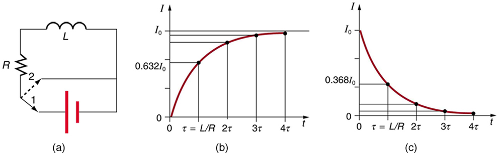
Figure 23.44 (a) An RL circuit with a switch to turn current on and off. When in position 1, the battery, resistor, and inductor are in series and a current is established. In position 2, the battery is removed and the current eventually stops because of energy loss in the resistor. (b) A graph of current growth versus time when the switch is moved
to position 1. (c) A graph of current decay when the switch is moved to position 2.
When the switch is first moved to position 1 (at t = 0 ), the current is zero and it eventually rises to I 0 = V/R , where R is the total resistance of the circuit. The opposition of the inductor L is greatest at the beginning, because the amount of change is greatest. The opposition it poses is in the
form of an induced emf, which decreases to zero as the current approaches its final value. The opposing emf is proportional to the amount of change
left. This is the hallmark of an exponential behavior, and it can be shown with calculus that
(23.45)
I = I 0(1 − e− t/ τ) (turning on),
is the current in an RL circuit when switched on (Note the similarity to the exponential behavior of the voltage on a charging capacitor). The initial
current is zero and approaches I 0 = V/R with a characteristic time constant τ for an RL circuit, given by
(23.46)
τ = LR,
where τ has units of seconds, since 1 H=1 Ω·s . In the first period of time τ , the current rises from zero to 0.632 I 0 , since
I = I 0(1 − e−1) = I 0(1 − 0.368) = 0.632 I 0 . The current will go 0.632 of the remainder in the next time τ . A well-known property of the exponential is that the final value is never exactly reached, but 0.632 of the remainder to that value is achieved in every characteristic time τ . In just
a few multiples of the time τ , the final value is very nearly achieved, as the graph in Figure 23.44(b) illustrates.
The characteristic time τ depends on only two factors, the inductance L and the resistance R . The greater the inductance L , the greater τ is, which makes sense since a large inductance is very effective in opposing change. The smaller the resistance R , the greater τ is. Again this makes
sense, since a small resistance means a large final current and a greater change to get there. In both cases—large L and small R —more energy
is stored in the inductor and more time is required to get it in and out.
When the switch in Figure 23.44(a) is moved to position 2 and cuts the battery out of the circuit, the current drops because of energy dissipation by
the resistor. But this is also not instantaneous, since the inductor opposes the decrease in current by inducing an emf in the same direction as the
battery that drove the current. Furthermore, there is a certain amount of energy, (1/2) LI 20 , stored in the inductor, and it is dissipated at a finite rate.
As the current approaches zero, the rate of decrease slows, since the energy dissipation rate is I 2 R . Once again the behavior is exponential, and
I is found to be
(23.47)
I = I 0 e− t/ τ (turning off).
(See Figure 23.44(c).) In the first period of time τ = L / R after the switch is closed, the current falls to 0.368 of its initial value, since I = I 0 e−1 = 0.368 I 0 . In each successive time τ , the current falls to 0.368 of the preceding value, and in a few multiples of τ , the current becomes very close to zero, as seen in the graph in Figure 23.44(c).
Example 23.9 Calculating Characteristic Time and Current in an RL Circuit
(a) What is the characteristic time constant for a 7.50 mH inductor in series with a 3.00 Ω resistor? (b) Find the current 5.00 ms after the switch
is moved to position 2 to disconnect the battery, if it is initially 10.0 A.
Strategy for (a)
The time constant for an RL circuit is defined by τ = L / R .
Solution for (a)
Entering known values into the expression for τ given in τ = L / R yields
(23.4
Describe what you're looking for in as much detail as you'd like.
Our AI reads your request and finds the best matching books for you.
Popular searches:
Join 2.9 million readers and get unlimited free ebooks