College Physics (2012) by Manjula Sharma, Paul Peter Urone, et al - HTML preview
Download the book in PDF, ePub, Kindle for a complete version.
Can Kirchhoff’s rules be applied to simple series and parallel circuits or are they restricted for use in more complicated circuits that are not
combinations of series and parallel?
Solution
Kirchhoff's rules can be applied to any circuit since they are applications to circuits of two conservation laws. Conservation laws are the most
broadly applicable principles in physics. It is usually mathematically simpler to use the rules for series and parallel in simpler circuits so we
emphasize Kirchhoff’s rules for use in more complicated situations. But the rules for series and parallel can be derived from Kirchhoff’s rules.
Moreover, Kirchhoff’s rules can be expanded to devices other than resistors and emfs, such as capacitors, and are one of the basic analysis
devices in circuit analysis.
21.4 DC Voltmeters and Ammeters
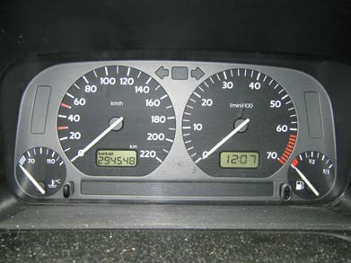
Voltmeters measure voltage, whereas ammeters measure current. Some of the meters in automobile dashboards, digital cameras, cell phones, and
tuner-amplifiers are voltmeters or ammeters. (See Figure 21.26.) The internal construction of the simplest of these meters and how they are
connected to the system they monitor give further insight into applications of series and parallel connections.
CHAPTER 21 | CIRCUITS, BIOELECTRICITY, AND DC INSTRUMENTS 753
Figure 21.26 The fuel and temperature gauges (far right and far left, respectively) in this 1996 Volkswagen are voltmeters that register the voltage output of “sender” units,
which are hopefully proportional to the amount of gasoline in the tank and the engine temperature. (credit: Christian Giersing)
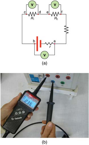
Voltmeters are connected in parallel with whatever device’s voltage is to be measured. A parallel connection is used because objects in parallel
experience the same potential difference. (See Figure 21.27, where the voltmeter is represented by the symbol V.)
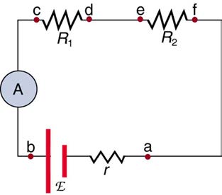
Ammeters are connected in series with whatever device’s current is to be measured. A series connection is used because objects in series have the
same current passing through them. (See Figure 21.28, where the ammeter is represented by the symbol A.)
Figure 21.27 (a) To measure potential differences in this series circuit, the voltmeter (V) is placed in parallel with the voltage source or either of the resistors. Note that terminal voltage is measured between points a and b. It is not possible to connect the voltmeter directly across the emf without including its internal resistance, r . (b) A digital
voltmeter in use. (credit: Messtechniker, Wikimedia Commons)
Figure 21.28 An ammeter (A) is placed in series to measure current. All of the current in this circuit flows through the meter. The ammeter would have the same reading if
located between points d and e or between points f and a as it does in the position shown. (Note that the script capital E stands for emf, and r stands for the internal
resistance of the source of potential difference.)
Analog Meters: Galvanometers
Analog meters have a needle that swivels to point at numbers on a scale, as opposed to digital meters, which have numerical readouts similar to a
hand-held calculator. The heart of most analog meters is a device called a galvanometer, denoted by G. Current flow through a galvanometer, I G ,
produces a proportional needle deflection. (This deflection is due to the force of a magnetic field upon a current-carrying wire.)
754 CHAPTER 21 | CIRCUITS, BIOELECTRICITY, AND DC INSTRUMENTS
The two crucial characteristics of a given galvanometer are its resistance and current sensitivity. Current sensitivity is the current that gives a full-
scale deflection of the galvanometer’s needle, the maximum current that the instrument can measure. For example, a galvanometer with a current
sensitivity of 50 μA has a maximum deflection of its needle when 50 μA flows through it, reads half-scale when 25 μA flows through it, and so
on.
If such a galvanometer has a 25- Ω resistance, then a voltage of only V = IR = ⎛⎝50 μA⎞⎠(25 Ω) = 1.25 mV produces a full-scale reading. By
connecting resistors to this galvanometer in different ways, you can use it as either a voltmeter or ammeter that can measure a broad range of
voltages or currents.
Galvanometer as Voltmeter
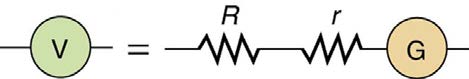
Figure 21.29 shows how a galvanometer can be used as a voltmeter by connecting it in series with a large resistance, R . The value of the
resistance R is determined by the maximum voltage to be measured. Suppose you want 10 V to produce a full-scale deflection of a voltmeter
containing a 25-Ω galvanometer with a 50-μA sensitivity. Then 10 V applied to the meter must produce a current of 50 μA . The total resistance
must be
(21.68)
R tot = R + r = VI = 10 V
50 μA = 200 kΩ, or
R
(21.69)
= R tot − r = 200 kΩ − 25 Ω ≈ 200 k Ω .
( R is so large that the galvanometer resistance, r , is nearly negligible.) Note that 5 V applied to this voltmeter produces a half-scale deflection by
producing a 25-μA current through the meter, and so the voltmeter’s reading is proportional to voltage as desired.
This voltmeter would not be useful for voltages less than about half a volt, because the meter deflection would be small and difficult to read
accurately. For other voltage ranges, other resistances are placed in series with the galvanometer. Many meters have a choice of scales. That choice
involves switching an appropriate resistance into series with the galvanometer.
Figure 21.29 A large resistance R placed in series with a galvanometer G produces a voltmeter, the full-scale deflection of which depends on the choice of R . The larger the voltage to be measured, the larger R must be. (Note that r represents the internal resistance of the galvanometer.)
Galvanometer as Ammeter
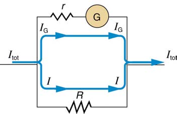
The same galvanometer can also be made into an ammeter by placing it in parallel with a small resistance R , often called the shunt resistance, as
shown in Figure 21.30. Since the shunt resistance is small, most of the current passes through it, allowing an ammeter to measure currents much
greater than those producing a full-scale deflection of the galvanometer.
Suppose, for example, an ammeter is needed that gives a full-scale deflection for 1.0 A, and contains the same 25- Ω galvanometer with its
50-μA sensitivity. Since R and r are in parallel, the voltage across them is the same.
These IR drops are IR = I G r so that IR = I G
I = Rr . Solving for R , and noting that I G is 50 μA and I is 0.999950 A, we have
(21.70)
R = rI G I = (25 Ω ) 50 μA
0.999950 A = 1.25 × 10⁻³ Ω .
Figure 21.30 A small shunt resistance R placed in parallel with a galvanometer G produces an ammeter, the full-scale deflection of which depends on the choice of R . The larger the current to be measured, the smaller R must be. Most of the current ( I ) flowing through the meter is shunted through R to protect the galvanometer. (Note that r represents the internal resistance of the galvanometer.) Ammeters may also have multiple scales for greater flexibility in application. The various scales are achieved by
switching various shunt resistances in parallel with the galvanometer—the greater the maximum current to be measured, the smaller the shunt resistance must be.
Taking Measurements Alters the Circuit
When you use a voltmeter or ammeter, you are connecting another resistor to an existing circuit and, thus, altering the circuit. Ideally, voltmeters and
ammeters do not appreciably affect the circuit, but it is instructive to examine the circumstances under which they do or do not interfere.
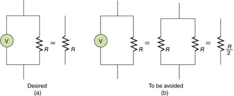
First, consider the voltmeter, which is always placed in parallel with the device being measured. Very little current flows through the voltmeter if its
resistance is a few orders of magnitude greater than the device, and so the circuit is not appreciably affected. (See Figure 21.31(a).) (A large
resistance in parallel with a small one has a combined resistance essentially equal to the small one.) If, however, the voltmeter’s resistance is
CHAPTER 21 | CIRCUITS, BIOELECTRICITY, AND DC INSTRUMENTS 755
comparable to that of the device being measured, then the two in parallel have a smaller resistance, appreciably affecting the circuit. (See Figure
21.31(b).) The voltage across the device is not the same as when the voltmeter is out of the circuit.
Figure 21.31 (a) A voltmeter having a resistance much larger than the device ( R Voltmeter >> R ) with which it is in parallel produces a parallel resistance essentially the same as the device and does not appreciably affect the circuit being measured. (b) Here the voltmeter has the same resistance as the device ( R Voltmeter ≅ R ), so that the parallel resistance is half of what it is when the voltmeter is not connected. This is an example of a significant alteration of the circuit and is to be avoided.
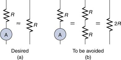
An ammeter is placed in series in the branch of the circuit being measured, so that its resistance adds to that branch. Normally, the ammeter’s
resistance is very small compared with the resistances of the devices in the circuit, and so the extra resistance is negligible. (See Figure 21.32(a).)
However, if very small load resistances are involved, or if the ammeter is not as low in resistance as it should be, then the total series resistance is
significantly greater, and the current in the branch being measured is reduced. (See Figure 21.32(b).)
A practical problem can occur if the ammeter is connected incorrectly. If it was put in parallel with the resistor to measure the current in it, you could
possibly damage the meter; the low resistance of the ammeter would allow most of the current in the circuit to go through the galvanometer, and this
current would be larger since the effective resistance is smaller.
Figure 21.32 (a) An ammeter normally has such a small resistance that the total series resistance in the branch being measured is not appreciably increased. The circuit is
essentially unaltered compared with when the ammeter is absent. (b) Here the ammeter’s resistance is the same as that of the branch, so that the total resistance is doubled
and the current is half what it is without the ammeter. This significant alteration of the circuit is to be avoided.
One solution to the problem of voltmeters and ammeters interfering with the circuits being measured is to use galvanometers with greater sensitivity.
This allows construction of voltmeters with greater resistance and ammeters with smaller resistance than when less sensitive galvanometers are
used.
There are practical limits to galvanometer sensitivity, but it is possible to get analog meters that make measurements accurate to a few percent. Note
that the inaccuracy comes from altering the circuit, not from a fault in the meter.
Connections: Limits to Knowledge
Making a measurement alters the system being measured in a manner that produces uncertainty in the measurement. For macroscopic systems,
such as the circuits discussed in this module, the alteration can usually be made negligibly small, but it cannot be eliminated entirely. For
submicroscopic systems, such as atoms, nuclei, and smaller particles, measurement alters the system in a manner that cannot be made
arbitrarily small. This actually limits knowledge of the system—even limiting what nature can know about itself. We shall see profound
implications of this when the Heisenberg uncertainty principle is discussed in the modules on quantum mechanics.
There is another measurement technique based on drawing no current at all and, hence, not altering the circuit at all. These are called null
measurements and are the topic of Null Measurements. Digital meters that employ solid-state electronics and null measurements can attain
accuracies of one part in 106 .
Digital meters are able to detect smaller currents than analog meters employing galvanometers. How does this explain their ability to measure
voltage and current more accurately than analog meters?
Solution
Since digital meters require less current than analog meters, they alter the circuit less than analog meters. Their resistance as a voltmeter can be
far greater than an analog meter, and their resistance as an ammeter can be far less than an analog meter. Consult Figure 21.27 and Figure
21.28 and their discussion in the text.
PhET Explorations: Circuit Construction Kit (DC Only), Virtual Lab
Stimulate a neuron and monitor what happens. Pause, rewind, and move forward in time in order to observe the ions as they move across the
neuron membrane.

756 CHAPTER 21 | CIRCUITS, BIOELECTRICITY, AND DC INSTRUMENTS
21.5 Null Measurements
Standard measurements of voltage and current alter the circuit being measured, introducing uncertainties in the measurements. Voltmeters draw
some extra current, whereas ammeters reduce current flow. Null measurements balance voltages so that there is no current flowing through the
measuring device and, therefore, no alteration of the circuit being measured.
Null measurements are generally more accurate but are also more complex than the use of standard voltmeters and ammeters, and they still have
limits to their precision. In this module, we shall consider a few specific types of null measurements, because they are common and interesting, and
they further illuminate principles of electric circuits.
The Potentiometer
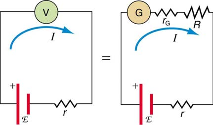
Suppose you wish to measure the emf of a battery. Consider what happens if you connect the battery directly to a standard voltmeter as shown in
Figure 21.34. (Once we note the problems with this measurement, we will examine a null measurement that improves accuracy.) As discussed
before, the actual quantity measured is the terminal voltage V , which is related to the emf of the battery by V = emf − Ir , where I is the current
that flows and r is the internal resistance of the battery.
The emf could be accurately calculated if r were very accurately known, but it is usually not. If the current I could be made zero, then V = emf ,
and so emf could be directly measured. However, standard voltmeters need a current to operate; thus, another technique is needed.
Figure 21.34 An analog voltmeter attached to a battery draws a small but nonzero current and measures a terminal voltage that differs from the emf of the battery. (Note that
the script capital E symbolizes electromotive force, or emf.) Since the internal resistance of the battery is not known precisely, it is not possible to calculate the emf precisely.
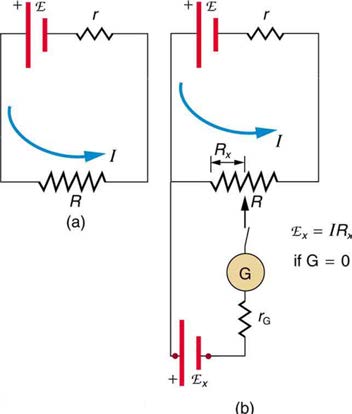
A potentiometer is a null measurement device for measuring potentials (voltages). (See Figure 21.35.) A voltage source is connected to a resistor
R, say, a long wire, and passes a constant current through it. There is a steady drop in potential (an IR drop) along the wire, so that a variable
potential can be obtained by making contact at varying locations along the wire.
Figure 21.35(b) shows an unknown emfx (represented by script E x in the figure) connected in series with a galvanometer. Note that emfx
opposes the other voltage source. The location of the contact point (see the arrow on the drawing) is adjusted until the galvanometer reads zero.
When the galvanometer reads zero, emfx = IR x , where R x is the resistance of the section of wire up to the contact point. Since no current flows
through the galvanometer, none flows through the unknown emf, and so emfx is directly sensed.
Now, a very precisely known standard emfs is substituted for emfx , and the contact point is adjusted until the galvanometer again reads zero, so
that emfs = IR s . In both cases, no current passes through the galvanometer, and so the current I through the long wire is the same. Upon taking
emf
the ratio
x
emf , I cancels, giving
s
(21.71)
emfx
emf = IR x = R x.
s
IR s R s
Solving for emfx gives
R
(21.72)
emfx = emfs x
R .
s
CHAPTER 21 | CIRCUITS, BIOELECTRICITY, AND DC INSTRUMENTS 757
Figure 21.35 The potentiometer, a null measurement device. (a) A voltage source connected to a long wire resistor passes a constant current I through it. (b) An unknown emf (labeled script E x in the figure) is connected as shown, and the point of contact along R is adjusted until the galvanometer reads zero. The segment of wire has a resistance R x and script E x = IR x , where I is unaffected by the connection since no current flows through the galvanometer. The unknown emf is thus proportional to the resistance of the wire segment.
Because a long uniform wire is used for R , the ratio of resistances R x / R s is the same as the ratio of the lengths of wire that zero the galvanometer
for each emf. The three quantities on the right-hand side of the equation are now known or measured, and emfx can be calculated. The uncertainty
in this calculation can be considerably smaller than when using a voltmeter directly, but it is not zero. There is always some uncertainty in the ratio of
resistances R x / R s and in the standard emfs . Furthermore, it is not possible to tell when the galvanometer reads exactly zero, which introduces
error into both R x and R s , and may also affect the current I .
Resistance Measurements and the Wheatstone Bridge
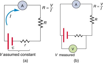
There is a variety of so-called ohmmeters that purport to measure resistance. What the most common ohmmeters actually do is to apply a voltage to
a resistance, measure the current, and calculate the resistance using Ohm’s law. Their readout is this calculated resistance. Two configurations for
ohmmeters using standard voltmeters and ammeters are shown in Figure 21.36. Such configurations are limited in accuracy, because the meters
alter both the voltage applied to the resistor and the current that flows through it.
Figure 21.36 Two methods for measuring resistance with standard meters. (a) Assuming a known voltage for the source, an ammeter measures current, and resistance is
calculated as R = VI . (b) Since the terminal voltage V varies with current, it is better to measure it. V is most accurately known when I is small, but I itself is most accurately known when it is large.
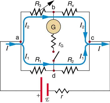
The Wheatstone bridge is a null measurement device for calculating resistance by balancing potential drops in a circuit. (See Figure 21.37.) The
device is called a bridge because the galvanometer forms a bridge between two branches. A variety of bridge devices are used to make null
measurements in circuits.
Resistors R 1 and R 2 are precisely known, while the arrow through R 3 indicates that it is a variable resistance. The value of R 3 can be precisely
read. With the unknown resistance R x in the circuit, R 3 is adjusted until the galvanometer reads zero. The potential difference between points b
and d is then zero, meaning that b and d are at the same potential. With no current running through the galvanometer, it has no effect on the rest of
the circuit. So the branches abc and adc are in parallel, and each branch has the full voltage of the source. That is, the IR drops along abc and adc
are the same. Since b and d are at the same potential, the IR drop along ad must equal the IR drop along ab. Thus,
I
(21.73)
1 R 1 = I 2 R 3.
Again, since b and d are at the same potential, the IR drop along dc must equal the IR drop along bc. Thus,
758 CHAPTER 21 | CIRCUITS, BIOELECTRICITY, AND DC INSTRUMENTS
I
(21.74)
1 R 2 = I 2 R x.
Taking the ratio of these last two expressions gives
I
(21.75)
1 R 1
I
= I 2 R 3.
1 R 2
I 2 R x
Canceling the currents and solving for Rx yields
R
(21.76)
R x = R 2
3 R .1
Figure 21.37 The Wheatstone bridge is used to calculate unknown resistances. The variable resistance R 3 is adjusted until the galvanometer reads zero with the switch
closed. This simplifies the circuit, allowing R x to be calculated based on the IR drops as discussed in the text.
This equation is used to calculate the unknown resistance when current through the galvanometer is zero. This method can be very accurate (often to
four significant digits), but it is limited by two factors. First, it is not possible to get the current through the galvanometer to be exactly zero. Second,
there are always uncertainties in R 1 , R 2 , and R 3 , which contribute to the uncertainty in R x .
Identify other factors that might limit the accuracy of null measurements. Would the use of a digital device that is more sensitive than a
galvanometer improve the accuracy of null measurements?
Solution
One factor would be resistance in the wires and connections in a null measurement. These are impossible to make zero, and they can change
over time. Another factor would be temperature variations in resistance, which can be reduced but not completely eliminated by choice of
material. Digital devices se