College Physics (2012) by Manjula Sharma, Paul Peter Urone, et al - HTML preview
Download the book in PDF, ePub, Kindle for a complete version.
(21.42)
I
p
2 = R = 9.65 V
2
6.00 Ω = 1.61 A.
Discussion for (c)
The current is less than the 2.00 A that flowed through R 2 when it was connected in parallel to the battery in the previous parallel circuit
example.
Strategy and Solution for (d)
The power dissipated by R 2 is given by
(21.43)
P 2 = ( I 2)2 R 2 = (1.61 A)2(6.00 Ω ) = 15.5 W.
Discussion for (d)
The power is less than the 24.0 W this resistor dissipated when connected in parallel to the 12.0-V source.
Practical Implications
One implication of this last example is that resistance in wires reduces the current and power delivered to a resistor. If wire resistance is relatively
large, as in a worn (or a very long) extension cord, then this loss can be significant. If a large current is drawn, the IR drop in the wires can also be
significant.
For example, when you are rummaging in the refrigerator and the motor comes on, the refrigerator light dims momentarily. Similarly, you can see the
passenger compartment light dim when you start the engine of your car (although this may be due to resistance inside the battery itself).
What is happening in these high-current situations is illustrated in Figure 21.7. The device represented by R 3 has a very low resistance, and so when it is switched on, a large current flows. This increased current causes a larger IR drop in the wires represented by R 1 , reducing the voltage
across the light bulb (which is R 2 ), which then dims noticeably.
Figure 21.7 Why do lights dim when a large appliance is switched on? The answer is that the large current the appliance motor draws causes a significant IR drop in the wires and reduces the voltage across the light.
Can any arbitrary combination of resistors be broken down into series and parallel combinations? See if you can draw a circuit diagram of
resistors that cannot be broken down into combinations of series and parallel.
Solution
No, there are many ways to connect resistors that are not combinations of series and parallel, including loops and junctions. In such cases
Kirchhoff’s rules, to be introduced in Kirchhoff’s Rules, will allow you to analyze the circuit.
Problem-Solving Strategies for Series and Parallel Resistors
1. Draw a clear circuit diagram, labeling all resistors and voltage sources. This step includes a list of the knowns for the problem, since they
are labeled in your circuit diagram.
2. Identify exactly what needs to be determined in the problem (identify the unknowns). A written list is useful.
3. Determine whether resistors are in series, parallel, or a combination of both series and parallel. Examine the circuit diagram to make this
assessment. Resistors are in series if the same current must pass sequentially through them.

742 CHAPTER 21 | CIRCUITS, BIOELECTRICITY, AND DC INSTRUMENTS
4. Use the appropriate list of major features for series or parallel connections to solve for the unknowns. There is one list for series and
another for parallel. If your problem has a combination of series and parallel, reduce it in steps by considering individual groups of series or
parallel connections, as done in this module and the examples. Special note: When finding R , the reciprocal must be taken with care.
5. Check to see whether the answers are reasonable and consistent. Units and numerical results must be reasonable. Total series resistance
should be greater, whereas total parallel resistance should be smaller, for example. Power should be greater for the same devices in
parallel compared with series, and so on.
21.2 Electromotive Force: Terminal Voltage
When you forget to turn off your car lights, they slowly dim as the battery runs down. Why don’t they simply blink off when the battery’s energy is
gone? Their gradual dimming implies that battery output voltage decreases as the battery is depleted.
Furthermore, if you connect an excessive number of 12-V lights in parallel to a car battery, they will be dim even when the battery is fresh and even if
the wires to the lights have very low resistance. This implies that the battery’s output voltage is reduced by the overload.
The reason for the decrease in output voltage for depleted or overloaded batteries is that all voltage sources have two fundamental parts—a source
of electrical energy and an internal resistance. Let us examine both.
Electromotive Force
You can think of many different types of voltage sources. Batteries themselves come in many varieties. There are many types of mechanical/electrical
generators, driven by many different energy sources, ranging from nuclear to wind. Solar cells create voltages directly from light, while thermoelectric
devices create voltage from temperature differences.
A few voltage sources are shown in Figure 21.8. All such devices create a potential difference and can supply current if connected to a resistance.
On the small scale, the potential difference creates an electric field that exerts force on charges, causing current. We thus use the name
electromotive force, abbreviated emf.
Emf is not a force at all; it is a special type of potential difference. To be precise, the electromotive force (emf) is the potential difference of a source
when no current is flowing. Units of emf are volts.
Figure 21.8 A variety of voltage sources (clockwise from top left): the Brazos Wind Farm in Fluvanna, Texas (credit: Leaflet, Wikimedia Commons); the Krasnoyarsk Dam in
Russia (credit: Alex Polezhaev); a solar farm (credit: U.S. Department of Energy); and a group of nickel metal hydride batteries (credit: Tiaa Monto). The voltage output of each
depends on its construction and load, and equals emf only if there is no load.
Electromotive force is directly related to the source of potential difference, such as the particular combination of chemicals in a battery. However, emf
differs from the voltage output of the device when current flows. The voltage across the terminals of a battery, for example, is less than the emf when
the battery supplies current, and it declines further as the battery is depleted or loaded down. However, if the device’s output voltage can be
measured without drawing current, then output voltage will equal emf (even for a very depleted battery).
Internal Resistance
As noted before, a 12-V truck battery is physically larger, contains more charge and energy, and can deliver a larger current than a 12-V motorcycle
battery. Both are lead-acid batteries with identical emf, but, because of its size, the truck battery has a smaller internal resistance r . Internal
resistance is the inherent resistance to the flow of current within the source itself.
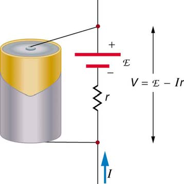
Figure 21.9 is a schematic representation of the two fundamental parts of any voltage source. The emf (represented by a script E in the figure) and internal resistance r are in series. The smaller the internal resistance for a given emf, the more current and the more power the source can supply.
CHAPTER 21 | CIRCUITS, BIOELECTRICITY, AND DC INSTRUMENTS 743
Figure 21.9 Any voltage source (in this case, a carbon-zinc dry cell) has an emf related to its source of potential difference, and an internal resistance r related to its construction. (Note that the script E stands for emf.). Also shown are the output terminals across which the terminal voltage V is measured. Since V = emf − Ir , terminal voltage equals emf only if there is no current flowing.
The internal resistance r can behave in complex ways. As noted, r increases as a battery is depleted. But internal resistance may also depend on
the magnitude and direction of the current through a voltage source, its temperature, and even its history. The internal resistance of rechargeable
nickel-cadmium cells, for example, depends on how many times and how deeply they have been depleted.
Things Great and Small: The Submicroscopic Origin of Battery Potential
Various types of batteries are available, with emfs determined by the combination of chemicals involved. We can view this as a molecular
reaction (what much of chemistry is about) that separates charge.
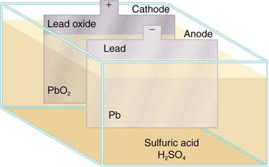
The lead-acid battery used in cars and other vehicles is one of the most common types. A single cell (one of six) of this battery is seen in Figure
plate. Both plates are immersed in sulfuric acid, the electrolyte for the system.
Figure 21.10 Artist’s conception of a lead-acid cell. Chemical reactions in a lead-acid cell separate charge, sending negative charge to the anode, which is connected to
the lead plates. The lead oxide plates are connected to the positive or cathode terminal of the cell. Sulfuric acid conducts the charge as well as participating in the
chemical reaction.
The details of the chemical reaction are left to the reader to pursue in a chemistry text, but their results at the molecular level help explain the
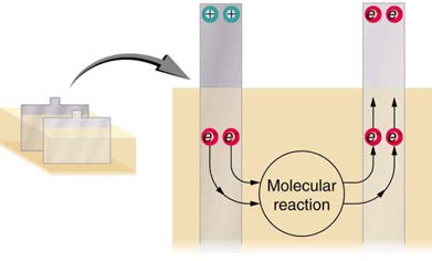
potential created by the battery. Figure 21.11 shows the result of a single chemical reaction. Two electrons are placed on the anode, making it
negative, provided that the cathode supplied two electrons. This leaves the cathode positively charged, because it has lost two electrons. In
short, a separation of charge has been driven by a chemical reaction.
Note that the reaction will not take place unless there is a complete circuit to allow two electrons to be supplied to the cathode. Under many
circumstances, these electrons come from the anode, flow through a resistance, and return to the cathode. Note also that since the chemical
reactions involve substances with resistance, it is not possible to create the emf without an internal resistance.
Figure 21.11 Artist’s conception of two electrons being forced onto the anode of a cell and two electrons being removed from the cathode of the cell. The chemical
reaction in a lead-acid battery places two electrons on the anode and removes two from the cathode. It requires a closed circuit to proceed, since the two electrons must
be supplied to the cathode.
744 CHAPTER 21 | CIRCUITS, BIOELECTRICITY, AND DC INSTRUMENTS
Why are the chemicals able to produce a unique potential difference? Quantum mechanical descriptions of molecules, which take into account the
types of atoms and numbers of electrons in them, are able to predict the energy states they can have and the energies of reactions between them.
In the case of a lead-acid battery, an energy of 2 eV is given to each electron sent to the anode. Voltage is defined as the electrical potential energy
divided by charge: V = P E
q . An electron volt is the energy given to a single electron by a voltage of 1 V. So the voltage here is 2 V, since 2 eV is
given to each electron. It is the energy produced in each molecular reaction that produces the voltage. A different reaction produces a different
energy and, hence, a different voltage.
Terminal Voltage
The voltage output of a device is measured across its terminals and, thus, is called its terminal voltage V . Terminal voltage is given by
V
(21.44)
= emf − Ir,
where r is the internal resistance and I is the current flowing at the time of the measurement.
I is positive if current flows away from the positive terminal, as shown in Figure 21.9. You can see that the larger the current, the smaller the terminal voltage. And it is likewise true that the larger the internal resistance, the smaller the terminal voltage.
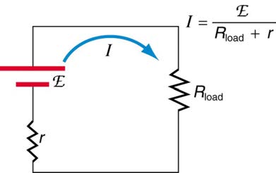
Suppose a load resistance R load is connected to a voltage source, as in Figure 21.12. Since the resistances are in series, the total resistance in the
circuit is R load + r . Thus the current is given by Ohm’s law to be
(21.45)
I = emf
R load + r.
Figure 21.12 Schematic of a voltage source and its load R load . Since the internal resistance r is in series with the load, it can significantly affect the terminal voltage and current delivered to the load. (Note that the script E stands for emf.)
We see from this expression that the smaller the internal resistance r , the greater the current the voltage source supplies to its load R load . As
batteries are depleted, r increases. If r becomes a significant fraction of the load resistance, then the current is significantly reduced, as the
following example illustrates.
Example 21.4 Calculating Terminal Voltage, Power Dissipation, Current, and Resistance: Terminal Voltage and
Load
A certain battery has a 12.0-V emf and an internal resistance of 0.100 Ω . (a) Calculate its terminal voltage when connected to a 10.0- Ω
load. (b) What is the terminal voltage when connected to a 0.500- Ω load? (c) What power does the 0.500- Ω load dissipate? (d) If the
internal resistance grows to 0.500 Ω , find the current, terminal voltage, and power dissipated by a 0.500- Ω load.
Strategy
The analysis above gave an expression for current when internal resistance is taken into account. Once the current is found, the terminal voltage
can be calculated using the equation V = emf − Ir . Once current is found, the power dissipated by a resistor can also be found.
Solution for (a)
Entering the given values for the emf, load resistance, and internal resistance into the expression above yields
(21.46)
I = emf
R load + r = 12.0 V
10.1 Ω = 1.188 A.
Enter the known values into the equation V = emf − Ir to get the terminal voltage:
V
(21.47)
= emf − Ir = 12.0 V − (1.188 A)(0.100 Ω)
= 11.9 V.
Discussion for (a)
The terminal voltage here is only slightly lower than the emf, implying that 10.0 Ω is a light load for this particular battery.
Solution for (b)
CHAPTER 21 | CIRCUITS, BIOELECTRICITY, AND DC INSTRUMENTS 745
Similarly, with R load = 0.500 Ω , the current is
(21.48)
I = emf
R load + r = 12.0 V
0.600 Ω = 20.0 A.
The terminal voltage is now
V
(21.49)
= emf − Ir = 12.0 V − (20.0 A)(0.100 Ω)
= 10.0 V.
Discussion for (b)
This terminal voltage exhibits a more significant reduction compared with emf, implying 0.500 Ω is a heavy load for this battery.
Solution for (c)
The power dissipated by the 0.500 - Ω load can be found using the formula P = I 2 R . Entering the known values gives
(21.50)
P load = I 2 R load = (20.0 A)2(0.500 Ω) = 2.00×10² W.
Discussion for (c)
Note that this power can also be obtained using the expressions V 2
R or IV , where V is the terminal voltage (10.0 V in this case).
Solution for (d)
Here the internal resistance has increased, perhaps due to the depletion of the battery, to the point where it is as great as the load resistance. As
before, we first find the current by entering the known values into the expression, yielding
(21.51)
I = emf
R load + r = 12.0 V
1.00 Ω = 12.0 A.
Now the terminal voltage is
V
(21.52)
= emf − Ir = 12.0 V − (12.0 A)(0.500 Ω)
= 6.00 V,
and the power dissipated by the load is
(21.53)
P load = I 2 R load = (12.0 A)2(0.500 Ω ) = 72.0 W.
Discussion for (d)
We see that the increased internal resistance has significantly decreased terminal voltage, current, and power delivered to a load.
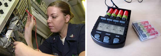
Battery testers, such as those in Figure 21.13, use small load resistors to intentionally draw current to determine whether the terminal voltage drops
below an acceptable level. They really test the internal resistance of the battery. If internal resistance is high, the battery is weak, as evidenced by its
low terminal voltage.
Figure 21.13 These two battery testers measure terminal voltage under a load to determine the condition of a battery. The large device is being used by a U.S. Navy
electronics technician to test large batteries aboard the aircraft carrier USS Nimitz and has a small resistance that can dissipate large amounts of power. (credit: U.S. Navy photo by Photographer’s Mate Airman Jason A. Johnston) The small device is used on small batteries and has a digital display to indicate the acceptability of their terminal
voltage. (credit: Keith Williamson)
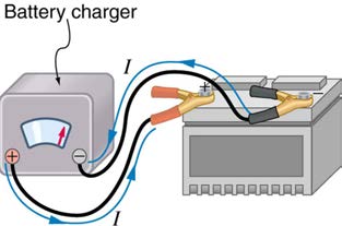
Some batteries can be recharged by passing a current through them in the direction opposite to the current they supply to a resistance. This is done
routinely in cars and batteries for small electrical appliances and electronic devices, and is represented pictorially in Figure 21.14. The voltage output
of the battery charger must be greater than the emf of the battery to reverse current through it. This will cause the terminal voltage of the battery to be
greater than the emf, since V = emf − Ir , and I is now negative.
746 CHAPTER 21 | CIRCUITS, BIOELECTRICITY, AND DC INSTRUMENTS
Figure 21.14 A car battery charger reverses the normal direction of current through a battery, reversing its chemical reaction and replenishing its chemical potential.
Multiple Voltage Sources
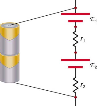
There are two voltage sources when a battery charger is used. Voltage sources connected in series are relatively simple. When voltage sources are
in series, their internal resistances add and their emfs add algebraically. (See Figure 21.15.) Series connections of voltage sources are common—for
example, in flashlights, toys, and other appliances. Usually, the cells are in series in order to produce a larger total emf.
But if the cells oppose one another, such as when one is put into an appliance backward, the total emf is less, since it is the algebraic sum of the
individual emfs.
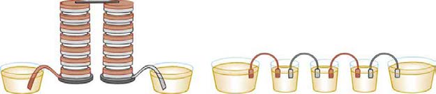
A battery is a multiple connection of voltaic cells, as shown in Figure 21.16. The disadvantage of series connections of cells is that their internal
resistances add. One of the authors once owned a 1957 MGA that had two 6-V batteries in series, rather than a single 12-V battery. This
arrangement produced a large internal resistance that caused him many problems in starting the engine.
Figure 21.15 A series connection of two voltage sources. The emfs (each labeled with a script E) and internal resistances add, giving a total emf of emf1 + emf2 and a
total internal resistance of r 1 + r 2 .
Figure 21.16 Batteries are multiple connections of individual cells, as shown in this modern rendition of an old print. Single cells, such as AA or C cells, are commonly called batteries, although this is technically incorrect.
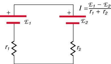
If the series connection of two voltage sources is made into a complete circuit with the emfs in opposition, then a current of magnitude
⎛
⎞
I = ⎝emf1 – emf2⎠
r
1 + r 2
⎛
⎞
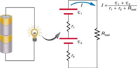
voltage sources in series with emfs in the same sense are connected to a load R
⎝emf1 + emf2⎠
load , as in Figure 21.18, then I = r
flows.
1 + r 2 + R load
CHAPTER 21 | CIRCUITS, BIOELECTRICITY, AND DC INSTRUMENTS 747
Figure 21.17 These two voltage sources are connected in series with their emfs in opposition. Current flows in the direction of the greater emf and is limited to
⎛
⎞
I = ⎝emf1 − emf2⎠
r
by the sum of the internal resistances. (Note that each emf is represented by script E in the figure.) A battery charger connected to a battery is an
1 + r 2
example of such a connection. The charger must have a larger emf than the battery to reverse current through it.
Figure 21.18 This schematic represents a flashlight with two cells (voltage sources) and a single bulb (load resistance) in series. The current that flows is
⎛
⎞
I = ⎝emf1 + emf2⎠
r
. (Note that each emf is represented by script E in the figure.)
1 + r 2 + R load
Take-Home Experiment: Flashlight Batteries
Find a flashlight that uses several batteries and find new and old batteries. Based on the discussions in this module, predict the brightness of the
flashlight when different combinations of batteries are used. Do your predictions match what you observe? Now place new batteries in the
flashlight and leave the flashlight switched on for several hours. Is the flashlight still quite bright? Do the same with the old batteries. Is the
flashlight as bright when left on for the same length of time with old and new batteries? What does this say for the case when you are limited in
the number of available new batteries?
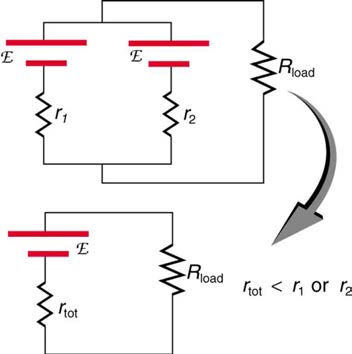
Figure 21.19 shows two voltage sources with identical emfs in parallel and connected to a load resistance. In this simple case, the total emf is the same as the individual emfs. But the total internal resistance is reduced, since the internal resistances are in parallel. The parallel connection thus
can produce a larger current.
Here, I =
emf
⎛
⎞ flows through the load, and r tot is less than those of the individual batteries. For example, some diesel-powered cars
⎝ r tot + R load⎠
use two 12-V batteries in parallel; they produce a total emf of 12 V but can deliver the larger current needed to start a diesel engine.
Figure 21.19 Two voltage sources with identical emfs (each labeled by script E) connected in parallel produce the same emf but have a smaller total internal resistance than
the individual sources. Parallel combinations are often used to deliver more current. Here