College Physics (2012) by Manjula Sharma, Paul Peter Urone, et al - HTML preview
Download the book in PDF, ePub, Kindle for a complete version.
passed? (b) What voltage was applied if 500 J of energy was dissipated?
design lighter-weight equipment at this higher frequency. What is the time (c) What was the path’s resistance? (d) Find the temperature increase
for one complete cycle of this power?
caused in the 8.00 kg of affected tissue.
76. A North American tourist takes his 25.0-W, 120-V AC razor to
93. Integrated Concepts
Europe, finds a special adapter, and plugs it into 240 V AC. Assuming
constant resistance, what power does the razor consume as it is ruined?
A short circuit in a 120-V appliance cord has a 0.500- Ω resistance.
77. In this problem, you will verify statements made at the end of the
Calculate the temperature rise of the 2.00 g of surrounding materials,
power losses for Example 20.10. (a) What current is needed to transmit
assuming their specific heat capacity is 0.200 cal/g⋅ºC and that it takes
100 MW of power at a voltage of 25.0 kV? (b) Find the power loss in a
1.00 - Ω
0.0500 s for a circuit breaker to interrupt the current. Is this likely to be
transmission line. (c) What percent loss does this represent?
damaging?
78. A small office-building air conditioner operates on 408-V AC and
94. Construct Your Own Problem
consumes 50.0 kW. (a) What is its effective resistance? (b) What is the
Consider a person working in an environment where electric currents
cost of running the air conditioner during a hot summer month when it is
might pass through her body. Construct a problem in which you calculate
on 8.00 h per day for 30 days and electricity costs 9.00 cents/kW ⋅ h ?
the resistance of insulation needed to protect the person from harm.
79. What is the peak power consumption of a 120-V AC microwave oven
Among the things to be considered are the voltage to which the person
that draws 10.0 A?
might be exposed, likely body resistance (dry, wet, …), and acceptable
currents (safe but sensed, safe and unfelt, …).
80. What is the peak current through a 500-W room heater that operates
on 120-V AC power?
20.7 Nerve Conduction–Electrocardiograms
81. Two different electrical devices have the same power consumption,
but one is meant to be operated on 120-V AC and the other on 240-V
95. Integrated Concepts
AC. (a) What is the ratio of their resistances? (b) What is the ratio of their
Use the ECG in Figure 20.34 to determine the heart rate in beats per
currents? (c) Assuming its resistance is unaffected, by what factor will the
minute assuming a constant time between beats.
power increase if a 120-V AC device is connected to 240-V AC?
96. Integrated Concepts
CHAPTER 20 | ELECTRIC CURRENT, RESISTANCE, AND OHM'S LAW 731
(a) Referring to Figure 20.34, find the time systolic pressure lags behind
the middle of the QRS complex. (b) Discuss the reasons for the time lag.
732 CHAPTER 20 | ELECTRIC CURRENT, RESISTANCE, AND OHM'S LAW

CHAPTER 21 | CIRCUITS, BIOELECTRICITY, AND DC INSTRUMENTS 733
21
CIRCUITS, BIOELECTRICITY, AND DC
INSTRUMENTS
Figure 21.1 The complexity of the electric circuits in a computer is surpassed by those in the human brain. (credit: Airman 1st Class Mike Meares, United States Air Force)
Learning Objectives
21.1. Resistors in Series and Parallel
• Draw a circuit with resistors in parallel and in series.
• Calculate the voltage drop of a current across a resistor using Ohm’s law.
• Contrast the way total resistance is calculated for resistors in series and in parallel.
• Explain why total resistance of a parallel circuit is less than the smallest resistance of any of the resistors in that circuit.
• Calculate total resistance of a circuit that contains a mixture of resistors connected in series and in parallel.
21.2. Electromotive Force: Terminal Voltage
• Compare and contrast the voltage and the electromagnetic force of an electric power source.
• Describe what happens to the terminal voltage, current, and power delivered to a load as internal resistance of the voltage source
increases (due to aging of batteries, for example).
• Explain why it is beneficial to use more than one voltage source connected in parallel.
• Analyze a complex circuit using Kirchhoff’s rules, using the conventions for determining the correct signs of various terms.
21.4. DC Voltmeters and Ammeters
• Explain why a voltmeter must be connected in parallel with the circuit.
• Draw a diagram showing an ammeter correctly connected in a circuit.
• Describe how a galvanometer can be used as either a voltmeter or an ammeter.
• Find the resistance that must be placed in series with a galvanometer to allow it to be used as a voltmeter with a given reading.
• Explain why measuring the voltage or current in a circuit can never be exact.
• Explain why a null measurement device is more accurate than a standard voltmeter or ammeter.
• Demonstrate how a Wheatstone bridge can be used to accurately calculate the resistance in a circuit.
21.6. DC Circuits Containing Resistors and Capacitors
• Explain the importance of the time constant, τ , and calculate the time constant for a given resistance and capacitance.
• Explain why batteries in a flashlight gradually lose power and the light dims over time.
• Describe what happens to a graph of the voltage across a capacitor over time as it charges.
• Explain how a timing circuit works and list some applications.
• Calculate the necessary speed of a strobe flash needed to “stop” the movement of an object over a particular length.
734 CHAPTER 21 | CIRCUITS, BIOELECTRICITY, AND DC INSTRUMENTS
Introduction to Circuits, Bioelectricity, and DC Instruments
Electric circuits are commonplace. Some are simple, such as those in flashlights. Others, such as those used in supercomputers, are extremely
complex.
This collection of modules takes the topic of electric circuits a step beyond simple circuits. When the circuit is purely resistive, everything in this
module applies to both DC and AC. Matters become more complex when capacitance is involved. We do consider what happens when capacitors
are connected to DC voltage sources, but the interaction of capacitors and other nonresistive devices with AC is left for a later chapter. Finally, a
number of important DC instruments, such as meters that measure voltage and current, are covered in this chapter.
21.1 Resistors in Series and Parallel
Most circuits have more than one component, called a resistor that limits the flow of charge in the circuit. A measure of this limit on charge flow is
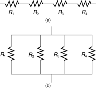
called resistance. The simplest combinations of resistors are the series and parallel connections illustrated in Figure 21.2. The total resistance of a combination of resistors depends on both their individual values and how they are connected.
Figure 21.2 (a) A series connection of resistors. (b) A parallel connection of resistors.
Resistors in Series
When are resistors in series? Resistors are in series whenever the flow of charge, called the current, must flow through devices sequentially. For
example, if current flows through a person holding a screwdriver and into the Earth, then R 1 in Figure 21.2(a) could be the resistance of the
screwdriver’s shaft, R 2 the resistance of its handle, R 3 the person’s body resistance, and R 4 the resistance of her shoes.
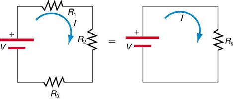
Figure 21.3 shows resistors in series connected to a voltage source. It seems reasonable that the total resistance is the sum of the individual resistances, considering that the current has to pass through each resistor in sequence. (This fact would be an advantage to a person wishing to
avoid an electrical shock, who could reduce the current by wearing high-resistance rubber-soled shoes. It could be a disadvantage if one of the
resistances were a faulty high-resistance cord to an appliance that would reduce the operating current.)
Figure 21.3 Three resistors connected in series to a battery (left) and the equivalent single or series resistance (right).
To verify that resistances in series do indeed add, let us consider the loss of electrical power, called a voltage drop, in each resistor in Figure 21.3.
According to Ohm’s law, the voltage drop, V , across a resistor when a current flows through it is calculated using the equation V = IR , where I
equals the current in amps (A) and R is the resistance in ohms ( Ω ) . Another way to think of this is that V is the voltage necessary to make a
current I flow through a resistance R .
So the voltage drop across R 1 is V 1 = IR 1 , that across R 2 is V 2 = IR 2 , and that across R 3 is V 3 = IR 3 . The sum of these voltages equals the voltage output of the source; that is,
V
(21.1)
= V 1 + V 2 + V 3.
This equation is based on the conservation of energy and conservation of charge. Electrical potential energy can be described by the equation
PE = qV , where q is the electric charge and V is the voltage. Thus the energy supplied by the source is qV , while that dissipated by the
resistors is
qV
(21.2)
1 + qV 2 + qV 3.
CHAPTER 21 | CIRCUITS, BIOELECTRICITY, AND DC INSTRUMENTS 735
Connections: Conservation Laws
The derivations of the expressions for series and parallel resistance are based on the laws of conservation of energy and conservation of charge,
which state that total charge and total energy are constant in any process. These two laws are directly involved in all electrical phenomena and
will be invoked repeatedly to explain both specific effects and the general behavior of electricity.
These energies must be equal, because there is no other source and no other destination for energy in the circuit. Thus, qV = qV 1 + qV 2 + qV 3 .
The charge q cancels, yielding V = V 1 + V 2 + V 3 , as stated. (Note that the same amount of charge passes through the battery and each resistor in a given amount of time, since there is no capacitance to store charge, there is no place for charge to leak, and charge is conserved.)
Now substituting the values for the individual voltages gives
V
(21.3)
= IR 1 + IR 2 + IR 3 = I( R 1 + R 2 + R 3).
Note that for the equivalent single series resistance R s , we have
V
(21.4)
= IR s.
This implies that the total or equivalent series resistance R s of three resistors is R s = R 1 + R 2 + R 3 .
This logic is valid in general for any number of resistors in series; thus, the total resistance R s of a series connection is
R
(21.5)
s = R 1 + R 2 + R 3 + ...,
as proposed. Since all of the current must pass through each resistor, it experiences the resistance of each, and resistances in series simply add up.
Example 21.1 Calculating Resistance, Current, Voltage Drop, and Power Dissipation: Analysis of a Series
Circuit
Suppose the voltage output of the battery in Figure 21.3 is 12.0 V , and the resistances are R 1 = 1.00 Ω , R 2 = 6.00 Ω , and
R 3 = 13.0 Ω . (a) What is the total resistance? (b) Find the current. (c) Calculate the voltage drop in each resistor, and show these add to
equal the voltage output of the source. (d) Calculate the power dissipated by each resistor. (e) Find the power output of the source, and show
that it equals the total power dissipated by the resistors.
Strategy and Solution for (a)
The total resistance is simply the sum of the individual resistances, as given by this equation:
R
(21.6)
s = R 1 + R 2 + R 3
= 1.00 Ω + 6.00 Ω + 13.0 Ω
= 20.0 Ω.
Strategy and Solution for (b)
The current is found using Ohm’s law, V = IR . Entering the value of the applied voltage and the total resistance yields the current for the
circuit:
(21.7)
I = V
R = 12.0 V
s
20.0 Ω = 0.600 A.
Strategy and Solution for (c)
The voltage—or IR drop—in a resistor is given by Ohm’s law. Entering the current and the value of the first resistance yields
V
(21.8)
1 = IR 1 = (0.600 A)(1.0 Ω ) = 0.600 V.
Similarly,
V
(21.9)
2 = IR 2 = (0.600 A)(6.0 Ω ) = 3.60 V
and
V
(21.10)
3 = IR 3 = (0.600 A)(13.0 Ω ) = 7.80 V.
Discussion for (c)
The three IR drops add to 12.0 V , as predicted:
V
(21.11)
1 + V 2 + V 3 = (0.600 + 3.60 + 7.80) V = 12.0 V.
Strategy and Solution for (d)
The easiest way to calculate power in watts (W) dissipated by a resistor in a DC circuit is to use Joule’s law, P = IV , where P is electric
power. In this case, each resistor has the same full current flowing through it. By substituting Ohm’s law V = IR into Joule’s law, we get the
power dissipated by the first resistor as
736 CHAPTER 21 | CIRCUITS, BIOELECTRICITY, AND DC INSTRUMENTS
(21.12)
P 1 = I 2 R 1 = (0.600 A)2(1.00 Ω ) = 0.360 W.
Similarly,
(21.13)
P 2 = I 2 R 2 = (0.600 A)2(6.00 Ω ) = 2.16 W
and
(21.14)
P 3 = I 2 R 3 = (0.600 A)2(13.0 Ω ) = 4.68 W.
Discussion for (d)
Power can also be calculated using either P = IV or P = V 2
R , where V is the voltage drop across the resistor (not the full voltage of the
source). The same values will be obtained.
Strategy and Solution for (e)
The easiest way to calculate power output of the source is to use P = IV , where V is the source voltage. This gives
P
(21.15)
= (0.600 A)(12.0 V) = 7.20 W.
Discussion for (e)
Note, coincidentally, that the total power dissipated by the resistors is also 7.20 W, the same as the power put out by the source. That is,
P
(21.16)
1 + P 2 + P 3 = (0.360 + 2.16 + 4.68) W = 7.20 W.
Power is energy per unit time (watts), and so conservation of energy requires the power output of the source to be equal to the total power
dissipated by the resistors.
Major Features of Resistors in Series
1. Series resistances add: R s = R 1 + R 2 + R 3 + ....
2. The same current flows through each resistor in series.
3. Individual resistors in series do not get the total source voltage, but divide it.
Resistors in Parallel
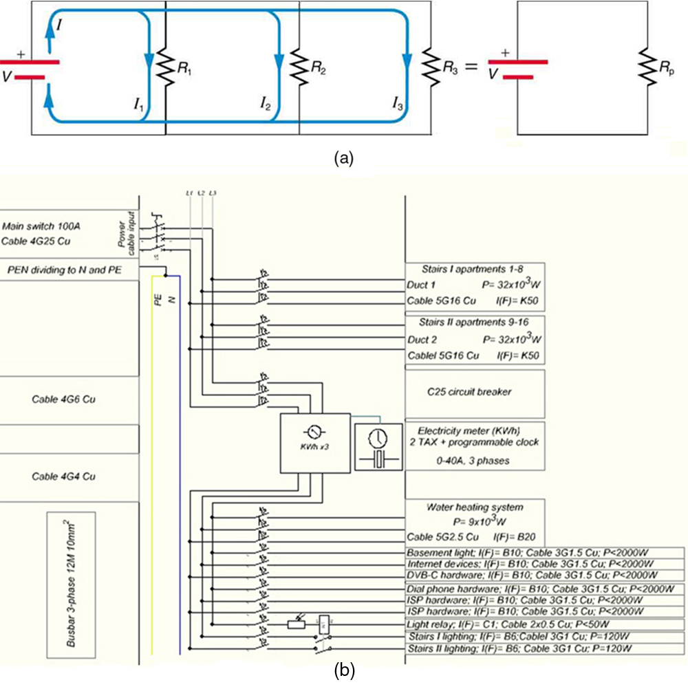
Figure 21.4 shows resistors in parallel, wired to a voltage source. Resistors are in parallel when each resistor is connected directly to the voltage source by connecting wires having negligible resistance. Each resistor thus has the full voltage of the source applied to it.
Each resistor draws the same current it would if it alone were connected to the voltage source (provided the voltage source is not overloaded). For
example, an automobile’s headlights, radio, and so on, are wired in parallel, so that they utilize the full voltage of the source and can operate
completely independently. The same is true in your house, or any building. (See Figure 21.4(b).)
CHAPTER 21 | CIRCUITS, BIOELECTRICITY, AND DC INSTRUMENTS 737
Figure 21.4 (a) Three resistors connected in parallel to a battery and the equivalent single or parallel resistance. (b) Electrical power setup in a house. (credit: Dmitry G,
Wikimedia Commons)
To find an expression for the equivalent parallel resistance R p , let us consider the currents that flow and how they are related to resistance. Since
each resistor in the circuit has the full voltage, the currents flowing through the individual resistors are I 1 = V
R , I
, and I
.
1
2 = V
R 2
3 = V
R 3
Conservation of charge implies that the total current I produced by the source is the sum of these currents:
I
(21.17)
= I 1 + I 2 + I 3.
Substituting the expressions for the individual currents gives
(21.18)
I = V
1
⎞
R + V + V = V⎛
+ 1 + 1
1
R 2 R 3
⎝ R 1 R 2 R 3⎠.
Note that Ohm’s law for the equivalent single resistance gives
(21.19)
⎛ ⎞
I = V
R = V
p
⎝ 1 R p⎠.
The terms inside the parentheses in the last two equations must be equal. Generalizing to any number of resistors, the total resistance R p of a
parallel connection is related to the individual resistances by
(21.20)
1
R = 1 + 1 + 1 + ....
p
R 1 R 2 R.3
This relationship results in a total resistance R p that is less than the smallest of the individual resistances. (This is seen in the next example.) When
resistors are connected in parallel, more current flows from the source than would flow for any of them individually, and so the total resistance is
lower.
738 CHAPTER 21 | CIRCUITS, BIOELECTRICITY, AND DC INSTRUMENTS
Example 21.2 Calculating Resistance, Current, Power Dissipation, and Power Output: Analysis of a Parallel
Circuit
Let the voltage output of the battery and resistances in the parallel connection in Figure 21.4 be the same as the previously considered series
connection: V = 12.0 V , R 1 = 1.00 Ω , R 2 = 6.00 Ω , and R 3 = 13.0 Ω . (a) What is the total resistance? (b) Find the total current.
(c) Calculate the currents in each resistor, and show these add to equal the total current output of the source. (d) Calculate the power dissipated
by each resistor. (e) Find the power output of the source, and show that it equals the total power dissipated by the resistors.
Strategy and Solution for (a)
The total resistance for a parallel combination of resistors is found using the equation below. Entering known values gives
(21.21)
1
R = 1 + 1 + 1 =
1
p
R 1 R 2 R 3 1.00 Ω +
1
6.00 Ω +
1
13.0 Ω .
Thus,
(21.22)
1
R = 1.00
p
Ω + 0.1667
Ω + 0.07692
Ω
= 1.2436
Ω .
(Note that in these calculations, each intermediate answer is shown with an extra digit.)
We must invert this to find the total resistance R p . This yields
(21.23)
R p = 1
1.2436 Ω = 0.8041 Ω .
The total resistance with the correct number of significant digits is R p = 0.804 Ω .
Discussion for (a)
R p is, as predicted, less than the smallest individual resistance.
Strategy and Solution for (b)
The total current can be found from Ohm’s law, substituting R p for the total resistance. This gives
(21.24)
I = V
R = 12.0 V
p
0.8041 Ω = 14.92 A.
Discussion for (b)
Current I for each device is much larger than for the same devices connected in series (see the previous example). A circuit with parallel
connections has a smaller total resistance than the resistors connected in series.
Strategy and Solution for (c)
The individual currents are easily calculated from Ohm’s law, since each resistor gets the full voltage. Thus,
(21.25)
I 1 = VR = 12.0 V
1
1.00 Ω = 12.0 A.
Similarly,
(21.26)
I 2 = VR = 12.0 V
2
6.00 Ω = 2.00 A
and
(21.27)
I 3 = VR = 12.0 V
3