College Physics (2012) by Manjula Sharma, Paul Peter Urone, et al - HTML preview
Download the book in PDF, ePub, Kindle for a complete version.
• Kirchhoff’s rules can be used to analyze any circuit, simple or complex.
• Kirchhoff’s first rule—the junction rule: The sum of all currents entering a junction must equal the sum of all currents leaving the junction.
• Kirchhoff’s second rule—the loop rule: The algebraic sum of changes in potential around any closed circuit path (loop) must be zero.
• The two rules are based, respectively, on the laws of conservation of charge and energy.
• When calculating potential and current using Kirchhoff’s rules, a set of conventions must be followed for determining the correct signs of various
terms.
• The simpler series and parallel rules are special cases of Kirchhoff’s rules.
21.4 DC Voltmeters and Ammeters
• Voltmeters measure voltage, and ammeters measure current.
• A voltmeter is placed in parallel with the voltage source to receive full voltage and must have a large resistance to limit its effect on the circuit.
• An ammeter is placed in series to get the full current flowing through a branch and must have a small resistance to limit its effect on the circuit.
• Both can be based on the combination of a resistor and a galvanometer, a device that gives an analog reading of current.
• Standard voltmeters and ammeters alter the circuit being measured and are thus limited in accuracy.
• Null measurement techniques achieve greater accuracy by balancing a circuit so that no current flows through the measuring device.
• One such device, for determining voltage, is a potentiometer.
• Another null measurement device, for determining resistance, is the Wheatstone bridge.
• Other physical quantities can also be measured with null measurement techniques.
21.6 DC Circuits Containing Resistors and Capacitors
• An RC circuit is one that has both a resistor and a capacitor.
• The time constant τ for an RC circuit is τ = RC .
• When an initially uncharged ( V 0 = 0 at t = 0 ) capacitor in series with a resistor is charged by a DC voltage source, the voltage rises,
asymptotically approaching the emf of the voltage source; as a function of time,
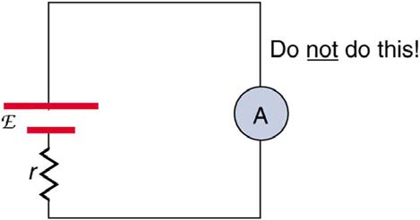
V = emf(1 − e− t / RC)(charging).
• Within the span of each time constant τ , the voltage rises by 0.632 of the remaining value, approaching the final voltage asymptotically.
• If a capacitor with an initial voltage V 0 is discharged through a resistor starting at t = 0 , then its voltage decreases exponentially as given by
V = V 0 e− t/ RC (discharging).
• In each time constant τ , the voltage falls by 0.368 of its remaining initial value, approaching zero asymptotically.
Conceptual Questions
21.1 Resistors in Series and Parallel
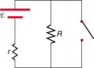
1. A switch has a variable resistance that is nearly zero when closed and extremely large when open, and it is placed in series with the device it
controls. Explain the effect the switch in Figure 21.43 has on current when open and when closed.
Figure 21.43 A switch is ordinarily in series with a resistance and voltage source. Ideally, the switch has nearly zero resistance when closed but has an extremely large
resistance when open. (Note that in this diagram, the script E represents the voltage (or electromotive force) of the battery.)
2. What is the voltage across the open switch in Figure 21.43?
3. There is a voltage across an open switch, such as in Figure 21.43. Why, then, is the power dissipated by the open switch small?
4. Why is the power dissipated by a closed switch, such as in Figure 21.43, small?
5. A student in a physics lab mistakenly wired a light bulb, battery, and switch as shown in Figure 21.44. Explain why the bulb is on when the switch
is open, and off when the switch is closed. (Do not try this—it is hard on the battery!)
CHAPTER 21 | CIRCUITS, BIOELECTRICITY, AND DC INSTRUMENTS 765
Figure 21.44 A wiring mistake put this switch in parallel with the device represented by R . (Note that in this diagram, the script E represents the voltage (or electromotive force) of the battery.)
6. Knowing that the severity of a shock depends on the magnitude of the current through your body, would you prefer to be in series or parallel with a
resistance, such as the heating element of a toaster, if shocked by it? Explain.
7. Would your headlights dim when you start your car’s engine if the wires in your automobile were superconductors? (Do not neglect the battery’s
internal resistance.) Explain.
8. Some strings of holiday lights are wired in series to save wiring costs. An old version utilized bulbs that break the electrical connection, like an
open switch, when they burn out. If one such bulb burns out, what happens to the others? If such a string operates on 120 V and has 40 identical
bulbs, what is the normal operating voltage of each? Newer versions use bulbs that short circuit, like a closed switch, when they burn out. If one such
bulb burns out, what happens to the others? If such a string operates on 120 V and has 39 remaining identical bulbs, what is then the operating
voltage of each?
9. If two household lightbulbs rated 60 W and 100 W are connected in series to household power, which will be brighter? Explain.
10. Suppose you are doing a physics lab that asks you to put a resistor into a circuit, but all the resistors supplied have a larger resistance than the
requested value. How would you connect the available resistances to attempt to get the smaller value asked for?
11. Before World War II, some radios got power through a “resistance cord” that had a significant resistance. Such a resistance cord reduces the
voltage to a desired level for the radio’s tubes and the like, and it saves the expense of a transformer. Explain why resistance cords become warm
and waste energy when the radio is on.
12. Some light bulbs have three power settings (not including zero), obtained from multiple filaments that are individually switched and wired in
parallel. What is the minimum number of filaments needed for three power settings?
21.2 Electromotive Force: Terminal Voltage
13. Is every emf a potential difference? Is every potential difference an emf? Explain.
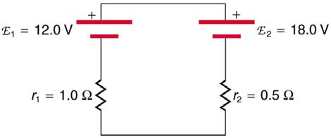
14. Explain which battery is doing the charging and which is being charged in Figure 21.45.
Figure 21.45
15. Given a battery, an assortment of resistors, and a variety of voltage and current measuring devices, describe how you would determine the
internal resistance of the battery.
16. Two different 12-V automobile batteries on a store shelf are rated at 600 and 850 “cold cranking amps.” Which has the smallest internal
resistance?
17. What are the advantages and disadvantages of connecting batteries in series? In parallel?
18. Semitractor trucks use four large 12-V batteries. The starter system requires 24 V, while normal operation of the truck’s other electrical
components utilizes 12 V. How could the four batteries be connected to produce 24 V? To produce 12 V? Why is 24 V better than 12 V for starting the
truck’s engine (a very heavy load)?
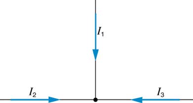
19. Can all of the currents going into the junction in Figure 21.46 be positive? Explain.
766 CHAPTER 21 | CIRCUITS, BIOELECTRICITY, AND DC INSTRUMENTS
Figure 21.46
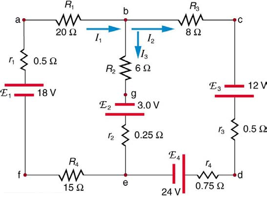
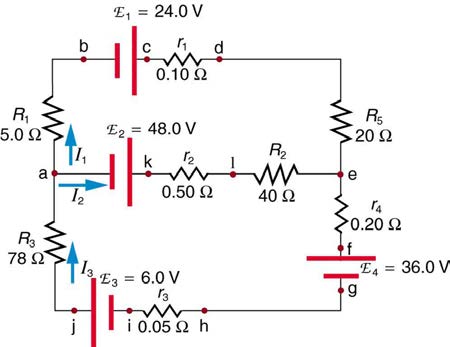
20. Apply the junction rule to junction b in Figure 21.47. Is any new information gained by applying the junction rule at e? (In the figure, each emf is
represented by script E.)
Figure 21.47
21. (a) What is the potential difference going from point a to point b in Figure 21.47? (b) What is the potential difference going from c to b? (c) From e to g? (d) From e to d?
22. Apply the loop rule to loop afedcba in Figure 21.47.
23. Apply the loop rule to loops abgefa and cbgedc in Figure 21.47.
21.4 DC Voltmeters and Ammeters
24. Why should you not connect an ammeter directly across a voltage source as shown in Figure 21.48? (Note that script E in the figure stands for
emf.)
Figure 21.48
25. Suppose you are using a multimeter (one designed to measure a range of voltages, currents, and resistances) to measure current in a circuit and
you inadvertently leave it in a voltmeter mode. What effect will the meter have on the circuit? What would happen if you were measuring voltage but
accidentally put the meter in the ammeter mode?
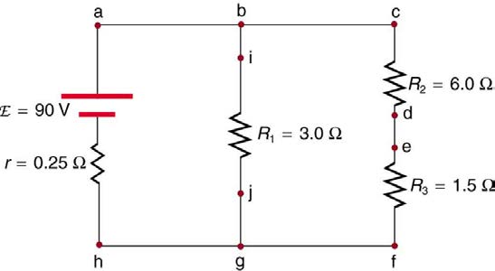
26. Specify the points to which you could connect a voltmeter to measure the following potential differences in Figure 21.49: (a) the potential
difference of the voltage source; (b) the potential difference across R 1 ; (c) across R 2 ; (d) across R 3 ; (e) across R 2 and R 3 . Note that there may be more than one answer to each part.
CHAPTER 21 | CIRCUITS, BIOELECTRICITY, AND DC INSTRUMENTS 767
Figure 21.49
27. To measure currents in Figure 21.49, you would replace a wire between two points with an ammeter. Specify the points between which you would place an ammeter to measure the following: (a) the total current; (b) the current flowing through R 1 ; (c) through R 2 ; (d) through R 3 . Note that
there may be more than one answer to each part.
28. Why can a null measurement be more accurate than one using standard voltmeters and ammeters? What factors limit the accuracy of null
measurements?
29. If a potentiometer is used to measure cell emfs on the order of a few volts, why is it most accurate for the standard emfs to be the same order of
magnitude and the resistances to be in the range of a few ohms?
21.6 DC Circuits Containing Resistors and Capacitors
30. Regarding the units involved in the relationship τ = RC , verify that the units of resistance times capacitance are time, that is, Ω ⋅ F = s .
31. The RC time constant in heart defibrillation is crucial to limiting the time the current flows. If the capacitance in the defibrillation unit is fixed, how
would you manipulate resistance in the circuit to adjust the RC constant τ ? Would an adjustment of the applied voltage also be needed to ensure
that the current delivered has an appropriate value?
32. When making an ECG measurement, it is important to measure voltage variations over small time intervals. The time is limited by the RC
constant of the circuit—it is not possible to measure time variations shorter than RC . How would you manipulate R and C in the circuit to allow the
necessary measurements?
33. Draw two graphs of charge versus time on a capacitor. Draw one for charging an initially uncharged capacitor in series with a resistor, as in the
circuit in Figure 21.38, starting from t = 0 . Draw the other for discharging a capacitor through a resistor, as in the circuit in Figure 21.39, starting at t = 0 , with an initial charge Q 0 . Show at least two intervals of τ .
34. When charging a capacitor, as discussed in conjunction with Figure 21.38, how long does it take for the voltage on the capacitor to reach emf? Is
this a problem?
35. When discharging a capacitor, as discussed in conjunction with Figure 21.39, how long does it take for the voltage on the capacitor to reach zero? Is this a problem?
36. Referring to Figure 21.38, draw a graph of potential difference across the resistor versus time, showing at least two intervals of τ . Also draw a graph of current versus time for this situation.
37. A long, inexpensive extension cord is connected from inside the house to a refrigerator outside. The refrigerator doesn’t run as it should. What
might be the problem?
38. In Figure 21.41, does the graph indicate the time constant is shorter for discharging than for charging? Would you expect ionized gas to have low resistance? How would you adjust R to get a longer time between flashes? Would adjusting R affect the discharge time?
39. An electronic apparatus may have large capacitors at high voltage in the power supply section, presenting a shock hazard even when the
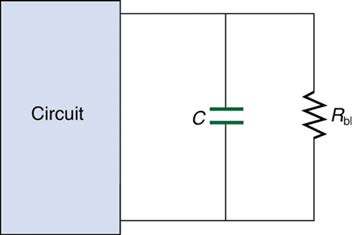
apparatus is switched off. A “bleeder resistor” is therefore placed across such a capacitor, as shown schematically in Figure 21.50, to bleed the
charge from it after the apparatus is off. Why must the bleeder resistance be much greater than the effective resistance of the rest of the circuit? How
does this affect the time constant for discharging the capacitor?
768 CHAPTER 21 | CIRCUITS, BIOELECTRICITY, AND DC INSTRUMENTS
Figure 21.50 A bleeder resistor R bl discharges the capacitor in this electronic device once it is switched off.
CHAPTER 21 | CIRCUITS, BIOELECTRICITY, AND DC INSTRUMENTS 769
Problems & Exercises
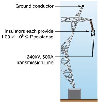
Figure 21.51 High-voltage (240-kV) transmission line carrying 5.00×10² A is
hung from a grounded metal transmission tower. The row of ceramic insulators
21.1 Resistors in Series and Parallel
provide 1.00×10⁹ Ω of resistance each.
Note: Data taken from figures can be assumed to be accurate to
11. Show that if two resistors R
three significant digits.
1 and R 2 are combined and one is
much greater than the other ( R
1. (a) What is the resistance of ten 275-Ω resistors connected in
1 >> R 2 ): (a) Their series resistance is
series? (b) In parallel?
very nearly equal to the greater resistance R 1 . (b) Their parallel
2. (a) What is the resistance of a 1.00×10² -Ω , a 2.50-kΩ , and a
resistance is very nearly equal to smaller resistance R 2 .
4.00-k Ω resistor connected in series? (b) In parallel?
12. Unreasonable Results
3. What are the largest and smallest resistances you can obtain by
Two resistors, one having a resistance of 145 Ω , are connected in
connecting a 36.0-Ω , a 50.0-Ω , and a 700-Ω resistor together?
parallel to produce a total resistance of 150 Ω . (a) What is the value of
4. An 1800-W toaster, a 1400-W electric frying pan, and a 75-W lamp are
the second resistance? (b) What is unreasonable about this result? (c)
plugged into the same outlet in a 15-A, 120-V circuit. (The three devices
Which assumptions are unreasonable or inconsistent?
are in parallel when plugged into the same socket.). (a) What current is
13. Unreasonable Results
drawn by each device? (b) Will this combination blow the 15-A fuse?
Two resistors, one having a resistance of 900 kΩ , are connected in
5. Your car’s 30.0-W headlight and 2.40-kW starter are ordinarily
connected in parallel in a 12.0-V system. What power would one
series to produce a total resistance of 0.500 MΩ . (a) What is the value
headlight and the starter consume if connected in series to a 12.0-V
of the second resistance? (b) What is unreasonable about this result? (c)
battery? (Neglect any other resistance in the circuit and any change in
Which assumptions are unreasonable or inconsistent?
resistance in the two devices.)
6. (a) Given a 48.0-V battery and 24.0-Ω and 96.0-Ω resistors, find
21.2 Electromotive Force: Terminal Voltage
the current and power for each when connected in series. (b) Repeat
14. Standard automobile batteries have six lead-acid cells in series,
when the resistances are in parallel.
creating a total emf of 12.0 V. What is the emf of an individual lead-acid
7. Referring to the example combining series and parallel circuits and
cell?
Figure 21.6, calculate I 3 in the following two different ways: (a) from the 15. Carbon-zinc dry cells (sometimes referred to as non-alkaline cells) have an emf of 1.54 V, and they are produced as single cells or in various
known values of I and I 2 ; (b) using Ohm’s law for R 3 . In both parts
combinations to form other voltages. (a) How many 1.54-V cells are
explicitly show how you follow the steps in the Problem-Solving
needed to make the common 9-V battery used in many small electronic
Strategies for Series and Parallel Resistors.
devices? (b) What is the actual emf of the approximately 9-V battery? (c)
Discuss how internal resistance in the series connection of cells will
8. Referring to Figure 21.6: (a) Calculate P 3 and note how it compares
affect the terminal voltage of this approximately 9-V battery.
with P 3 found in the first two example problems in this module. (b) Find 16. What is the output voltage of a 3.0000-V lithium cell in a digital
the total power supplied by the source and compare it with the sum of the
wristwatch that draws 0.300 mA, if the cell’s internal resistance is
powers dissipated by the resistors.
2.00 Ω ?
9. Refer to Figure 21.7 and the discussion of lights dimming when a
17. (a) What is the terminal voltage of a large 1.54-V carbon-zinc dry cell
heavy appliance comes on. (a) Given the voltage source is 120 V, the
used in a physics lab to supply 2.00 A to a circuit, if the cell’s internal
wire resistance is 0.800 Ω , and the bulb is nominally 75.0 W, what
resistance is 0.100 Ω ? (b) How much electrical power does the cell
power will the bulb dissipate if a total of 15.0 A passes through the wires
produce? (c) What power goes to its load?
when the motor comes on? Assume negligible change in bulb resistance.
(b) What power is consumed by the motor?
18. What is the internal resistance of an automobile battery that has an
emf of 12.0 V and a terminal voltage of 15.0 V while a current of 8.00 A is
10. A 240-kV power transmission line carrying 5.00×10² A is hung
charging it?
from grounded metal towers by ceramic insulators, each having a
19. (a) Find the terminal voltage of a 12.0-V motorcycle battery having a
1.00 × 10⁹ -Ω resistance. Figure 21.51. (a) What is the resistance to
0.600-Ω internal resistance, if it is being charged by a current of 10.0 A.
ground of 100 of these insulators? (b) Calculate the power dissipated by
(b) What is the output voltage of the battery charger?
100 of them. (c) What fraction of the power carried by the line is this?
20. A car battery with a 12-V emf and an internal resistance of
Explicitly show how you follow the steps in the Problem-Solving
0.050 Ω is being charged with a current of 60 A. Note that in this
Strategies for Series and Parallel Resistors.
process the battery is being charged. (a) What is the potential difference
across its terminals? (b) At what rate is thermal energy being dissipated
in the battery? (c) At what rate is electric energy being converted to
chemical energy? (d) What are the answers to (a) and (b) when the
battery is used to supply 60 A to the starter motor?
21. The hot resistance of a flashlight bulb is 2.30 Ω , and it is run by a
1.58-V alkaline cell having a 0.100-Ω internal resistance. (a) What
current flows? (b) Calculate the power supplied to the bulb using
I 2 R bulb . (c) Is this power the same as calculated using V 2
R
?
bulb
22. The label on a portable radio recommends the use of rechargeable
nickel-cadmium cells (nicads), although they have a 1.25-V emf while
alkaline cells have a 1.58-V emf. The radio has a 3.20-Ω resistance. (a)
Draw a circuit diagram of the radio and its batteries. Now, calculate the
power delivered to the radio. (b) When using Nicad cells each having an
770 CHAPTER 21 | CIRCUITS, BIOELECTRICITY, AND DC INSTRUMENTS
internal resistance of 0.0400 Ω . (c) When using alkaline cells each
33. Verify the second equation in Example 21.5 by substituting the
having an internal resistance of 0.200 Ω . (d) Does this difference seem values found for the currents I 1 and I 2 .
significant, considering that the radio’s effective resistance is lowered
34. Verify the third equation in Example 21.5 by substituting the values
when its volume is turned up?
found for the currents I 1 and I 3 .
23. An automobile starter motor has an equivalent resistance of
0.0500 Ω and is supplied by a 12.0-V battery with a 0.0100-Ω
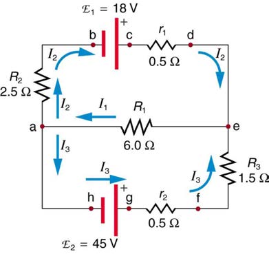
35. Apply the junction rule at point a in Figure 21.52.
internal resistance. (a) What is the current to the mo