College Physics (2012) by Manjula Sharma, Paul Peter Urone, et al - HTML preview
Download the book in PDF, ePub, Kindle for a complete version.
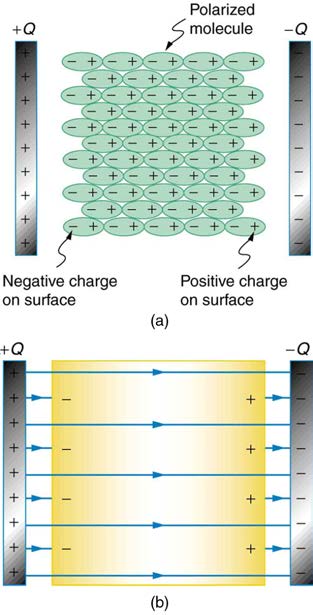
dielectric material placed between the charged plates of a capacitor. The Coulomb force between the closest ends of the molecules and the charge
on the plates is attractive and very strong, since they are very close together. This attracts more charge onto the plates than if the space were empty
and the opposite charges were a distance d away.
680 CHAPTER 19 | ELECTRIC POTENTIAL AND ELECTRIC FIELD
Figure 19.17 (a) The molecules in the insulating material between the plates of a capacitor are polarized by the charged plates. This produces a layer of opposite charge on
the surface of the dielectric that attracts more charge onto the plate, increasing its capacitance. (b) The dielectric reduces the electric field strength inside the capacitor,
resulting in a smaller voltage between the plates for the same charge. The capacitor stores the same charge for a smaller voltage, implying that it has a larger capacitance
because of the dielectric.
Another way to understand how a dielectric increases capacitance is to consider its effect on the electric field inside the capacitor. Figure 19.17(b) shows the electric field lines with a dielectric in place. Since the field lines end on charges in the dielectric, there are fewer of them going from one
side of the capacitor to the other. So the electric field strength is less than if there were a vacuum between the plates, even though the same charge
is on the plates. The voltage between the plates is V = Ed , so it too is reduced by the dielectric. Thus there is a smaller voltage V for the same
charge Q ; since C = Q / V , the capacitance C is greater.
The dielectric constant is generally defined to be κ = E 0 / E , or the ratio of the electric field in a vacuum to that in the dielectric material, and is
intimately related to the polarizability of the material.
Things Great and Small
The Submicroscopic Origin of Polarization
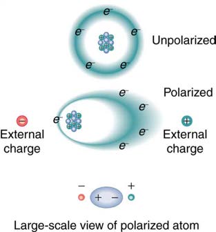
Polarization is a separation of charge within an atom or molecule. As has been noted, the planetary model of the atom pictures it as having a
positive nucleus orbited by negative electrons, analogous to the planets orbiting the Sun. Although this model is not completely accurate, it is
very helpful in explaining a vast range of phenomena and will be refined elsewhere, such as in Atomic Physics. The submicroscopic origin of
polarization can be modeled as shown in Figure 19.18.
Figure 19.18 Artist’s conception of a polarized atom. The orbits of electrons around the nucleus are shifted slightly by the external charges (shown exaggerated). The resulting separation of charge within the atom means that it is polarized. Note that the unlike charge is now closer to the external charges, causing the polarization.

CHAPTER 19 | ELECTRIC POTENTIAL AND ELECTRIC FIELD 681
We will find in Atomic Physics that the orbits of electrons are more properly viewed as electron clouds with the density of the cloud related to the probability of finding an electron in that location (as opposed to the definite locations and paths of planets in their orbits around the Sun). This cloud is
shifted by the Coulomb force so that the atom on average has a separation of charge. Although the atom remains neutral, it can now be the source of
a Coulomb force, since a charge brought near the atom will be closer to one type of charge than the other.
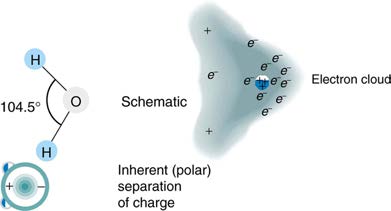
Some molecules, such as those of water, have an inherent separation of charge and are thus called polar molecules. Figure 19.19 illustrates the
separation of charge in a water molecule, which has two hydrogen atoms and one oxygen atom ⎛⎝H2 O⎞⎠ . The water molecule is not symmetric—the
hydrogen atoms are repelled to one side, giving the molecule a boomerang shape. The electrons in a water molecule are more concentrated around
the more highly charged oxygen nucleus than around the hydrogen nuclei. This makes the oxygen end of the molecule slightly negative and leaves
the hydrogen ends slightly positive. The inherent separation of charge in polar molecules makes it easier to align them with external fields and
charges. Polar molecules therefore exhibit greater polarization effects and have greater dielectric constants. Those who study chemistry will find that
the polar nature of water has many effects. For example, water molecules gather ions much more effectively because they have an electric field and
a separation of charge to attract charges of both signs. Also, as brought out in the previous chapter, polar water provides a shield or screening of the
electric fields in the highly charged molecules of interest in biological systems.
Figure 19.19 Artist’s conception of a water molecule. There is an inherent separation of charge, and so water is a polar molecule. Electrons in the molecule are attracted to the oxygen nucleus and leave an excess of positive charge near the two hydrogen nuclei. (Note that the schematic on the right is a rough illustration of the distribution of electrons
in the water molecule. It does not show the actual numbers of protons and electrons involved in the structure.)
PhET Explorations: Capacitor Lab
Explore how a capacitor works! Change the size of the plates and add a dielectric to see the effect on capacitance. Change the voltage and see
charges built up on the plates. Observe the electric field in the capacitor. Measure the voltage and the electric field.
Figure 19.20 Capacitor Lab (http://cnx.org/content/m42333/1.4/capacitor-lab_en.jar)
19.6 Capacitors in Series and Parallel
Several capacitors may be connected together in a variety of applications. Multiple connections of capacitors act like a single equivalent capacitor.
The total capacitance of this equivalent single capacitor depends both on the individual capacitors and how they are connected. There are two simple
and common types of connections, called series and parallel, for which we can easily calculate the total capacitance. Certain more complicated
connections can also be related to combinations of series and parallel.
Capacitance in Series
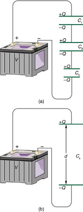
Figure 19.21(a) shows a series connection of three capacitors with a voltage applied. As for any capacitor, the capacitance of the combination is
related to charge and voltage by C = Q
V .
Note in Figure 19.21 that opposite charges of magnitude Q flow to either side of the originally uncharged combination of capacitors when the voltage V is applied. Conservation of charge requires that equal-magnitude charges be created on the plates of the individual capacitors, since
charge is only being separated in these originally neutral devices. The end result is that the combination resembles a single capacitor with an
effective plate separation greater than that of the individual capacitors alone. (See Figure 19.21(b).) Larger plate separation means smaller
capacitance. It is a general feature of series connections of capacitors that the total capacitance is less than any of the individual capacitances.
682 CHAPTER 19 | ELECTRIC POTENTIAL AND ELECTRIC FIELD
Figure 19.21 (a) Capacitors connected in series. The magnitude of the charge on each plate is Q . (b) An equivalent capacitor has a larger plate separation d . Series connections produce a total capacitance that is less than that of any of the individual capacitors.
We can find an expression for the total capacitance by considering the voltage across the individual capacitors shown in Figure 19.21. Solving
C = QV for V gives V = QC . The voltages across the individual capacitors are thus V 1 = QC , V
, and V
. The total voltage is
1
2 = Q
C 2
3 = Q
C 3
the sum of the individual voltages:
V
(19.60)
= V 1 + V 2 + V 3.
Now, calling the total capacitance C S for series capacitance, consider that
(19.61)
V = Q
C = V
S
1 + V 2 + V 3 .
Entering the expressions for V 1 , V 2 , and V 3 , we get
Q
(19.62)
C = Q + Q + Q .
S
C 1 C 2 C 3
Canceling the Q s, we obtain the equation for the total capacitance in series C S to be
(19.63)
1
C = 1 + 1 + 1 + ...,
S
C 1 C 2 C 3
where “...” indicates that the expression is valid for any number of capacitors connected in series. An expression of this form always results in a total
capacitance C S that is less than any of the individual capacitances C 1 , C 2 , ..., as the next example illustrates.
Total Capacitance in Series, C s
Total capacitance in series: 1
C = 1 + 1 + 1 + ...
S
C 1 C 2 C 3
CHAPTER 19 | ELECTRIC POTENTIAL AND ELECTRIC FIELD 683
Example 19.9 What Is the Series Capacitance?
Find the total capacitance for three capacitors connected in series, given their individual capacitances are 1.000, 5.000, and 8.000 µF .
Strategy
With the given information, the total capacitance can be found using the equation for capacitance in series.
Solution
Entering the given capacitances into the expression for 1
C gives 1 = 1 + 1 + 1 .
S
CS C 1 C 2 C 3
(19.64)
1
C =
1
S
1.000 µF +
1
5.000 µF +
1
8.000 µF = 1.325
µF
Inverting to find C S yields C S = µF
1.325 = 0.755 µF .
Discussion
The total series capacitance C s is less than the smallest individual capacitance, as promised. In series connections of capacitors, the sum is
less than the parts. In fact, it is less than any individual. Note that it is sometimes possible, and more convenient, to solve an equation like the
above by finding the least common denominator, which in this case (showing only whole-number calculations) is 40. Thus,
(19.65)
1
C = 40
S
40 µF + 8
40 µF + 5
40 µF = 53
40 µF,
so that
(19.66)
C S = 40 µF
53 = 0.755 µF.
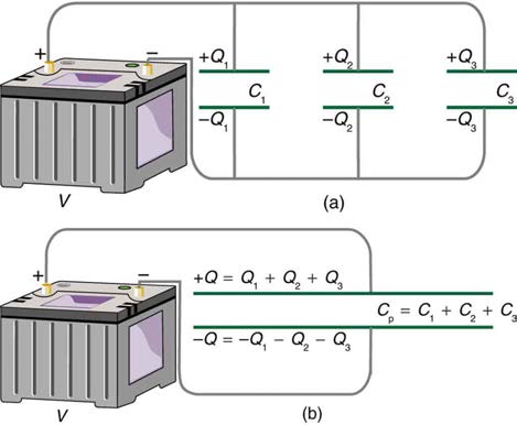
Capacitors in Parallel
Figure 19.22(a) shows a parallel connection of three capacitors with a voltage applied. Here the total capacitance is easier to find than in the series case. To find the equivalent total capacitance C p , we first note that the voltage across each capacitor is V , the same as that of the source, since
they are connected directly to it through a conductor. (Conductors are equipotentials, and so the voltage across the capacitors is the same as that
across the voltage source.) Thus the capacitors have the same charges on them as they would have if connected individually to the voltage source.
The total charge Q is the sum of the individual charges:
Q
(19.67)
= Q 1 + Q 2 + Q 3.
Figure 19.22 (a) Capacitors in parallel. Each is connected directly to the voltage source just as if it were all alone, and so the total capacitance in parallel is just the sum of the individual capacitances. (b) The equivalent capacitor has a larger plate area and can therefore hold more charge than the individual capacitors.
Using the relationship Q = CV , we see that the total charge is Q = C p V , and the individual charges are Q 1 = C 1 V , Q 2 = C 2 V , and Q 3 = C 3 V . Entering these into the previous equation gives
C
(19.68)
p V = C 1 V + C 2 V + C 3 V.
Canceling V from the equation, we obtain the equation for the total capacitance in parallel C p :
C
(19.69)
p = C 1 + C 2 + C 3 + ....
684 CHAPTER 19 | ELECTRIC POTENTIAL AND ELECTRIC FIELD
Total capacitance in parallel is simply the sum of the individual capacitances. (Again the “... ” indicates the expression is valid for any number of
capacitors connected in parallel.) So, for example, if the capacitors in the example above were connected in parallel, their capacitance would be
C
(19.70)
p = 1.000 µF+5.000 µF+8.000 µF = 14.000 µF.
The equivalent capacitor for a parallel connection has an effectively larger plate area and, thus, a larger capacitance, as illustrated in Figure
19.22(b).
Total Capacitance in Parallel, C p
Total capacitance in parallel C p = C 1 + C 2 + C 3 + . .
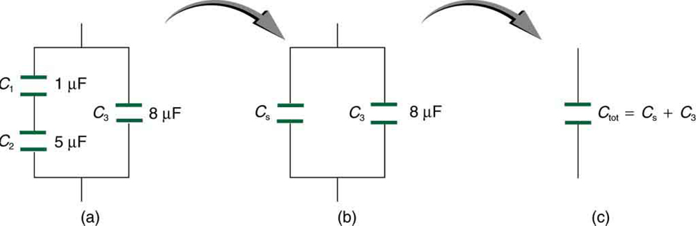
More complicated connections of capacitors can sometimes be combinations of series and parallel. (See Figure 19.23.) To find the total capacitance
of such combinations, we identify series and parallel parts, compute their capacitances, and then find the total.
Figure 19.23 (a) This circuit contains both series and parallel connections of capacitors. See Example 19.10 for the calculation of the overall capacitance of the circuit. (b) C 1 and C 2 are in series; their equivalent capacitance C S is less than either of them. (c) Note that C S is in parallel with C 3 . The total capacitance is, thus, the sum of C S and C 3 .
Example 19.10 A Mixture of Series and Parallel Capacitance
Find the total capacitance of the combination of capacitors shown in Figure 19.23. Assume the capacitances in Figure 19.23 are known to three decimal places ( C 1 = 1.000 µF , C 2 = 3.000 µF , and C 3 = 8.000 µF ), and round your answer to three decimal places.
Strategy
To find the total capacitance, we first identify which capacitors are in series and which are in parallel. Capacitors C 1 and C 2 are in series.
Their combination, labeled C S in the figure, is in parallel with C 3 .
Solution
Since C 1 and C 2 are in series, their total capacitance is given by 1
C = 1 + 1 + 1 . Entering their values into the equation gives
S
C 1 C 2 C 3
(19.71)
1
C = 1 + 1 =
1
S
C 1 C 2 1.000 μF +
1
5.000 μF = 1.200
μF .
Inverting gives
C
(19.72)
S = 0.833 µF.
This equivalent series capacitance is in parallel with the third capacitor; thus, the total is the sum
C
(19.73)
tot = C S + C S
= 0.833 μF + 8.000 μF
= 8.833 μF.
Discussion
This technique of analyzing the combinations of capacitors piece by piece until a total is obtained can be applied to larger combinations of
capacitors.
19.7 Energy Stored in Capacitors
Most of us have seen dramatizations in which medical personnel use a defibrillator to pass an electric current through a patient’s heart to get it to
beat normally. (Review Figure 19.24.) Often realistic in detail, the person applying the shock directs another person to “make it 400 joules this time.”
The energy delivered by the defibrillator is stored in a capacitor and can be adjusted to fit the situation. SI units of joules are often employed. Less
CHAPTER 19 | ELECTRIC POTENTIAL AND ELECTRIC FIELD 685
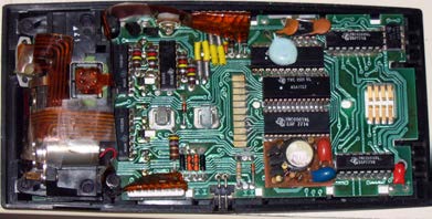
dramatic is the use of capacitors in microelectronics, such as certain handheld calculators, to supply energy when batteries are charged. (See Figure
19.24.) Capacitors are also used to supply energy for flash lamps on cameras.
Figure 19.24 Energy stored in the large capacitor is used to preserve the memory of an electronic calculator when its batteries are charged. (credit: Kucharek, Wikimedia
Commons)
Energy stored in a capacitor is electrical potential energy, and it is thus related to the charge Q and voltage V on the capacitor. We must be careful
when applying the equation for electrical potential energy ΔPE = qΔ V to a capacitor. Remember that ΔPE is the potential energy of a charge q
going through a voltage Δ V . But the capacitor starts with zero voltage and gradually comes up to its full voltage as it is charged. The first charge
placed on a capacitor experiences a change in voltage Δ V = 0 , since the capacitor has zero voltage when uncharged. The final charge placed on a
capacitor experiences Δ V = V , since the capacitor now has its full voltage V on it. The average voltage on the capacitor during the charging
process is V / 2 , and so the average voltage experienced by the full charge q is V / 2 . Thus the energy stored in a capacitor, E cap , is
(19.74)
E cap = QV
2 ,
where Q is the charge on a capacitor with a voltage V applied. (Note that the energy is not QV , but QV / 2 .) Charge and voltage are related to
the capacitance C of a capacitor by Q = CV , and so the expression for E cap can be algebraically manipulated into three equivalent expressions:
(19.75)
E cap = QV
2 = CV 2
2 = Q 2
2 C,
where Q is the charge and V the voltage on a capacitor C . The energy is in joules for a charge in coulombs, voltage in volts, and capacitance in
farads.
Energy Stored in Capacitors
The energy stored in a capacitor can be expressed in three ways:
(19.76)
E cap = QV
2 = CV 2
2 = Q 2
2 C,
where Q is the charge, V is the voltage, and C is the capacitance of the capacitor. The energy is in joules for a charge in coulombs, voltage
in volts, and capacitance in farads.
In a defibrillator, the delivery of a large charge in a short burst to a set of paddles across a person’s chest can be a lifesaver. The person’s heart
attack might have arisen from the onset of fast, irregular beating of the heart—cardiac or ventricular fibrillation. The application of a large shock of
electrical energy can terminate the arrhythmia and allow the body’s pacemaker to resume normal patterns. Today it is common for ambulances to
carry a defibrillator, which also uses an electrocardiogram to analyze the patient’s heartbeat pattern. Automated external defibrillators (AED) are
found in many public places (Figure 19.25). These are designed to be used by lay persons. The device automatically diagnoses the patient’s heart
condition and then applies the shock with appropriate energy and waveform. CPR is recommended in many cases before use of an AED.
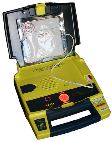
686 CHAPTER 19 | ELECTRIC POTENTIAL AND ELECTRIC FIELD
Figure 19.25 Automated external defibrillators are found in many public places. These portable units provide verbal instructions for use in the important first few minutes for a person suffering a cardiac attack. (credit: Owain Davies, Wikimedia Commons)
Example 19.11 Capacitance in a Heart Defibrillator
A heart defibrillator delivers 4.00×10² J of energy by discharging a capacitor initially at 1.00×10⁴ V . What is its capacitance?
Strategy
We are given E cap and V , and we are asked to find the capacitance C . Of the three expressions in the equation for E cap , the most
convenient relationship is
(19.77)
E cap = CV 2
2 .
Solution
Solving this expression for C and entering the given values yields
(19.78)
C = 2 E cap
V 2 = 2(4.00 × 10² J)
(1.00 × 10⁴ V)2 = 8.00 × 10 – 6 F
= 8.00 µF.
Discussion
This is a fairly large, but manageable, capacitance at 1.00×10⁴ V .
Glossary
capacitance: amount of charge stored per unit volt
capacitor: a device that stores electric charge
defibrillator: a machine used to provide an electrical shock to a heart attack victim's heart in order to restore the heart's normal rhythmic pattern
dielectric strength: the maximum electric field above which an insulating material begins to break down and conduct
dielectric: an insulating material
electric potential: potential energy per unit charge