College Physics (2012) by Manjula Sharma, Paul Peter Urone, et al - HTML preview
Download the book in PDF, ePub, Kindle for a complete version.
Otto cycle, heat transfer Q c from the gas at constant volume reduces its temperature and pressure, returning it to its original state. In an internal
combustion engine, this process corresponds to the exhaust of hot gases and the intake of an air-gasoline mixture at a considerably lower
temperature. In both cases, heat transfer into the environment occurs along this final path.
The net work done by a cyclical process is the area inside the closed path on a PV diagram, such as that inside path ABCDA in Figure 15.19. Note
that in every imaginable cyclical process, it is absolutely necessary for heat transfer from the system to occur in order to get a net work output. In the
Otto cycle, heat transfer occurs along path DA. If no heat transfer occurs, then the return path is the same, and the net work output is zero. The lower
the temperature on the path AB, the less work has to be done to compress the gas. The area inside the closed path is then greater, and so the
engine does more work and is thus more efficient. Similarly, the higher the temperature along path CD, the more work output there is. (See Figure
15.20.) So efficiency is related to the temperatures of the hot and cold reservoirs. In the next section, we shall see what the absolute limit to the efficiency of a heat engine is, and how it is related to temperature.
Figure 15.18 In the four-stroke internal combustion gasoline engine, heat transfer into work takes place in the cyclical process shown here. The piston is connected to a
rotating crankshaft, which both takes work out of and does work on the gas in the cylinder. (a) Air is mixed with fuel during the intake stroke. (b) During the compression stroke,
the air-fuel mixture is rapidly compressed in a nearly adiabatic process, as the piston rises with the valves closed. Work is done on the gas. (c) The power stroke has two
distinct parts. First, the air-fuel mixture is ignited, converting chemical potential energy into thermal energy almost instantaneously, which leads to a great increase in pressure.
Then the piston descends, and the gas does work by exerting a force through a distance in a nearly adiabatic process. (d) The exhaust stroke expels the hot gas to prepare
the engine for another cycle, starting again with the intake stroke.
Figure 15.19 PV diagram for a simplified Otto cycle, analogous to that employed in an internal combustion engine. Point A corresponds to the start of the compression
stroke of an internal combustion engine. Paths AB and CD are adiabatic and correspond to the compression and power strokes of an internal combustion engine, respectively.
Paths BC and DA are isochoric and accomplish similar results to the ignition and exhaust-intake portions, respectively, of the internal combustion engine’s cycle. Work is done
on the gas along path AB, but more work is done by the gas along path CD, so that there is a net work output.

522 CHAPTER 15 | THERMODYNAMICS
Figure 15.20 This Otto cycle produces a greater work output than the one in Figure 15.19, because the starting temperature of path CD is higher and the starting temperature
of path AB is lower. The area inside the loop is greater, corresponding to greater net work output.
15.4 Carnot’s Perfect Heat Engine: The Second Law of Thermodynamics Restated
Figure 15.21 This novelty toy, known as the drinking bird, is an example of Carnot’s engine. It contains methylene chloride (mixed with a dye) in the abdomen, which boils at a
very low temperature—about 100ºF . To operate, one gets the bird’s head wet. As the water evaporates, fluid moves up into the head, causing the bird to become top-heavy
and dip forward back into the water. This cools down the methylene chloride in the head, and it moves back into the abdomen, causing the bird to become bottom heavy and
tip up. Except for a very small input of energy—the original head-wetting—the bird becomes a perpetual motion machine of sorts. (credit: Arabesk.nl, Wikimedia Commons)
We know from the second law of thermodynamics that a heat engine cannot be 100% efficient, since there must always be some heat transfer Q c to
the environment, which is often called waste heat. How efficient, then, can a heat engine be? This question was answered at a theoretical level in
1824 by a young French engineer, Sadi Carnot (1796–1832), in his study of the then-emerging heat engine technology crucial to the Industrial
Revolution. He devised a theoretical cycle, now called the Carnot cycle, which is the most efficient cyclical process possible. The second law of
thermodynamics can be restated in terms of the Carnot cycle, and so what Carnot actually discovered was this fundamental law. Any heat engine
employing the Carnot cycle is called a Carnot engine.
What is crucial to the Carnot cycle—and, in fact, defines it—is that only reversible processes are used. Irreversible processes involve dissipative
factors, such as friction and turbulence. This increases heat transfer Q c to the environment and reduces the efficiency of the engine. Obviously,
then, reversible processes are superior.
Carnot Engine
Stated in terms of reversible processes, the second law of thermodynamics has a third form:
A Carnot engine operating between two given temperatures has the greatest possible efficiency of any heat engine operating between these two
temperatures. Furthermore, all engines employing only reversible processes have this same maximum efficiency when operating between the
same given temperatures.
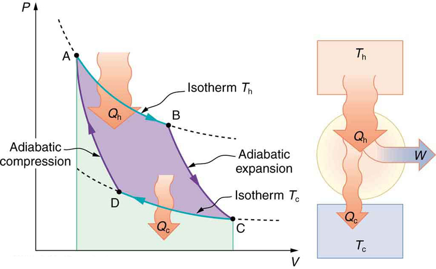
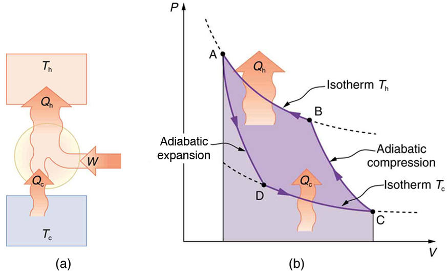
Figure 15.22 shows the PV diagram for a Carnot cycle. The cycle comprises two isothermal and two adiabatic processes. Recall that both
isothermal and adiabatic processes are, in principle, reversible.
Carnot also determined the efficiency of a perfect heat engine—that is, a Carnot engine. It is always true that the efficiency of a cyclical heat engine is
given by:
CHAPTER 15 | THERMODYNAMICS 523
(15.33)
Eff = Q h − Q c
Q
= 1 − Q c.
h
Q h
What Carnot found was that for a perfect heat engine, the ratio Q c / Q h equals the ratio of the absolute temperatures of the heat reservoirs. That is,
Q c / Q h = T c / T h for a Carnot engine, so that the maximum or Carnot efficiency Eff C is given by
(15.34)
Eff C = 1 − T c
T ,
h
where T h and T c are in kelvins (or any other absolute temperature scale). No real heat engine can do as well as the Carnot efficiency—an actual
efficiency of about 0.7 of this maximum is usually the best that can be accomplished. But the ideal Carnot engine, like the drinking bird above, while a
fascinating novelty, has zero power. This makes it unrealistic for any applications.
Carnot’s interesting result implies that 100% efficiency would be possible only if T c = 0 K —that is, only if the cold reservoir were at absolute zero,
a practical and theoretical impossibility. But the physical implication is this—the only way to have all heat transfer go into doing work is to remove all
thermal energy, and this requires a cold reservoir at absolute zero.
It is also apparent that the greatest efficiencies are obtained when the ratio T c / T h is as small as possible. Just as discussed for the Otto cycle in
the previous section, this means that efficiency is greatest for the highest possible temperature of the hot reservoir and lowest possible temperature
of the cold reservoir. (This setup increases the area inside the closed loop on the PV diagram; also, it seems reasonable that the greater the
temperature difference, the easier it is to divert the heat transfer to work.) The actual reservoir temperatures of a heat engine are usually related to
the type of heat source and the temperature of the environment into which heat transfer occurs. Consider the following example.
Figure 15.22 PV diagram for a Carnot cycle, employing only reversible isothermal and adiabatic processes. Heat transfer Q h occurs into the working substance during the isothermal path AB, which takes place at constant temperature T h . Heat transfer Q c occurs out of the working substance during the isothermal path CD, which takes place at constant temperature T c . The net work output W equals the area inside the path ABCDA. Also shown is a schematic of a Carnot engine operating between hot and cold reservoirs at temperatures T h and T c . Any heat engine using reversible processes and operating between these two temperatures will have the same maximum efficiency
as the Carnot engine.
Example 15.4 Maximum Theoretical Efficiency for a Nuclear Reactor
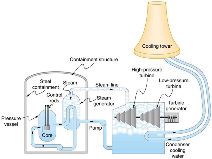
A nuclear power reactor has pressurized water at 300ºC . (Higher temperatures are theoretically possible but practically not, due to limitations
with materials used in the reactor.) Heat transfer from this water is a complex process (see Figure 15.23). Steam, produced in the steam
generator, is used to drive the turbine-generators. Eventually the steam is condensed to water at 27ºC and then heated again to start the cycle
over. Calculate the maximum theoretical efficiency for a heat engine operating between these two temperatures.
524 CHAPTER 15 | THERMODYNAMICS
Figure 15.23 Schematic diagram of a pressurized water nuclear reactor and the steam turbines that convert work into electrical energy. Heat exchange is used to
generate steam, in part to avoid contamination of the generators with radioactivity. Two turbines are used because this is less expensive than operating a single generator
that produces the same amount of electrical energy. The steam is condensed to liquid before being returned to the heat exchanger, to keep exit steam pressure low and
aid the flow of steam through the turbines (equivalent to using a lower-temperature cold reservoir). The considerable energy associated with condensation must be
dissipated into the local environment; in this example, a cooling tower is used so there is no direct heat transfer to an aquatic environment. (Note that the water going to
the cooling tower does not come into contact with the steam flowing over the turbines.)
Strategy
Since temperatures are given for the hot and cold reservoirs of this heat engine, Eff = 1 − T c
C
T h can be used to calculate the Carnot (maximum
theoretical) efficiency. Those temperatures must first be converted to kelvins.
Solution
The hot and cold reservoir temperatures are given as 300ºC and 27.0ºC , respectively. In kelvins, then, T h = 573 K and T c = 300 K , so
that the maximum efficiency is
(15.35)
Eff = 1 − T c
C
T .
h
Thus,
(15.36)
Eff C = 1 − 300 K
573 K
= 0.476, or 47.6%.
Discussion
A typical nuclear power station’s actual efficiency is about 35%, a little better than 0.7 times the maximum possible value, a tribute to superior
engineering. Electrical power stations fired by coal, oil, and natural gas have greater actual efficiencies (about 42%), because their boilers can
reach higher temperatures and pressures. The cold reservoir temperature in any of these power stations is limited by the local environment.
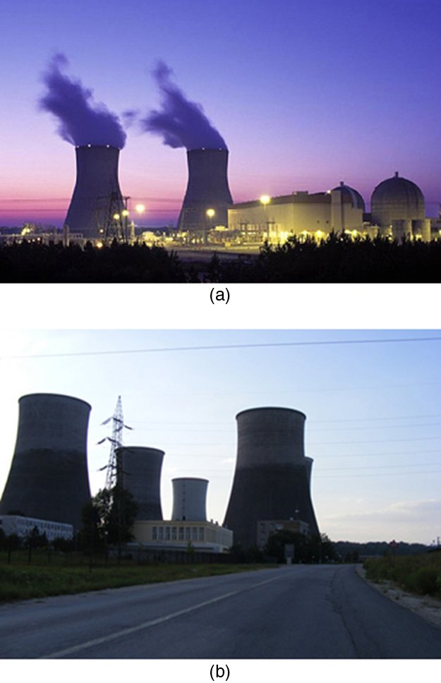
Figure 15.24 shows (a) the exterior of a nuclear power station and (b) the exterior of a coal-fired power station. Both have cooling towers into
which water from the condenser enters the tower near the top and is sprayed downward, cooled by evaporation.
CHAPTER 15 | THERMODYNAMICS 525
Figure 15.24 (a) A nuclear power station (credit: BlatantWorld.com) and (b) a coal-fired power station. Both have cooling towers in which water evaporates into the
environment, representing Q c . The nuclear reactor, which supplies Q h , is housed inside the dome-shaped containment buildings. (credit: Robert & Mihaela Vicol,
publicphoto.org)
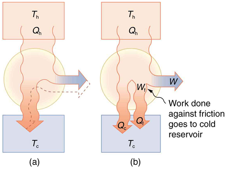
Since all real processes are irreversible, the actual efficiency of a heat engine can never be as great as that of a Carnot engine, as illustrated in
Figure 15.25(a). Even with the best heat engine possible, there are always dissipative processes in peripheral equipment, such as electrical
transformers or car transmissions. These further reduce the overall efficiency by converting some of the engine’s work output back into heat transfer,
as shown in Figure 15.25(b).
Figure 15.25 Real heat engines are less efficient than Carnot engines. (a) Real engines use irreversible processes, reducing the heat transfer to work. Solid lines represent
the actual process; the dashed lines are what a Carnot engine would do between the same two reservoirs. (b) Friction and other dissipative processes in the output
mechanisms of a heat engine convert some of its work output into heat transfer to the environment.
526 CHAPTER 15 | THERMODYNAMICS
15.5 Applications of Thermodynamics: Heat Pumps and Refrigerators
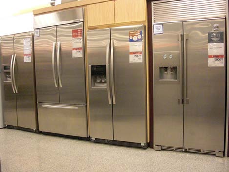
Figure 15.26 Almost every home contains a refrigerator. Most people don’t realize they are also sharing their homes with a heat pump. (credit: Id1337x, Wikimedia Commons)
Heat pumps, air conditioners, and refrigerators utilize heat transfer from cold to hot. They are heat engines run backward. We say backward, rather
than reverse, because except for Carnot engines, all heat engines, though they can be run backward, cannot truly be reversed. Heat transfer occurs
from a cold reservoir Q c and into a hot one. This requires work input W , which is also converted to heat transfer. Thus the heat transfer to the hot
reservoir is Q h = Q c + W . (Note that Q h , Q c , and W are positive, with their directions indicated on schematics rather than by sign.) A heat pump’s mission is for heat transfer Q h to occur into a warm environment, such as a home in the winter. The mission of air conditioners and
refrigerators is for heat transfer Q c to occur from a cool environment, such as chilling a room or keeping food at lower temperatures than the
environment. (Actually, a heat pump can be used both to heat and cool a space. It is essentially an air conditioner and a heating unit all in one. In this
section we will concentrate on its heating mode.)
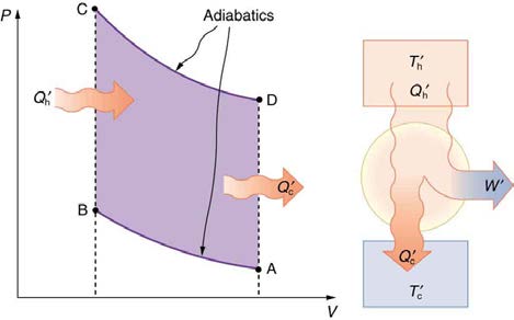
Figure 15.27 Heat pumps, air conditioners, and refrigerators are heat engines operated backward. The one shown here is based on a Carnot (reversible) engine. (a)
Schematic diagram showing heat transfer from a cold reservoir to a warm reservoir with a heat pump. The directions of W , Q h , and Q c are opposite what they would be in a heat engine. (b) PV diagram for a Carnot cycle similar to that in Figure 15.28 but reversed, following path ADCBA. The area inside the loop is negative, meaning there is a net work input. There is heat transfer Q c into the system from a cold reservoir along path DC, and heat transfer Q h out of the system into a hot reservoir along path BA.
Heat Pumps
The great advantage of using a heat pump to keep your home warm, rather than just burning fuel, is that a heat pump supplies Q h = Q c + W .
Heat transfer is from the outside air, even at a temperature below freezing, to the indoor space. You only pay for W , and you get an additional heat
transfer of Q c from the outside at no cost; in many cases, at least twice as much energy is transferred to the heated space as is used to run the heat
pump. When you burn fuel to keep warm, you pay for all of it. The disadvantage is that the work input (required by the second law of
thermodynamics) is sometimes more expensive than simply burning fuel, especially if the work is done by electrical energy.
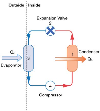
The basic components of a heat pump in its heating mode are shown in Figure 15.28. A working fluid such as a non-CFC refrigerant is used. In the
outdoor coils (the evaporator), heat transfer Q c occurs to the working fluid from the cold outdoor air, turning it into a gas.
CHAPTER 15 | THERMODYNAMICS 527
Figure 15.28 A simple heat pump has four basic components: (1) condenser, (2) expansion valve, (3) evaporator, and (4) compressor. In the heating mode, heat transfer Q c occurs to the working fluid in the evaporator (3) from the colder outdoor air, turning it into a gas. The electrically driven compressor (4) increases the temperature and pressure
of the gas and forces it into the condenser coils (1) inside the heated space. Because the temperature of the gas is higher than the temperature in the room, heat transfer from
the gas to the room occurs as the gas condenses to a liquid. The working fluid is then cooled as it flows back through an expansion valve (2) to the outdoor evaporator coils.
The electrically driven compressor (work input W ) raises the temperature and pressure of the gas and forces it into the condenser coils that are
inside the heated space. Because the temperature of the gas is higher than the temperature inside the room, heat transfer to the room occurs and the
gas condenses to a liquid. The liquid then flows back through a pressure-reducing valve to the outdoor evaporator coils, being cooled through
expansion. (In a cooling cycle, the evaporator and condenser coils exchange roles and the flow direction of the fluid is reversed.)
The quality of a heat pump is judged by how much heat transfer Q h occurs into the warm space compared with how much work input W is
required. In the spirit of taking the ratio of what you get to what you spend, we define a heat pump’s coefficient of performance ( COP hp ) to be
(15.37)
COP hp = Q h
W .
Since the efficiency of a heat engine is Eff = W / Q h , we see that COP hp = 1 / Eff , an important and interesting fact. First, since the efficiency of any heat engine is less than 1, it means that COP hp is always greater than 1—that is, a heat pump always has more heat transfer Q h than work
put into it. Second, it means that heat pumps work best when temperature differences are small. The efficiency of a perfect, or Carnot, engine is
Eff
⎞
C = 1 − ⎛⎝ T c / T h⎠ ; thus, the smaller the temperature difference, the smaller the efficiency and the greater the COP hp (because
COP hp = 1 / Eff ). In other words, heat pumps do not work as well in very cold climates as they do in more moderate climates.
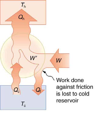
Friction and other irreversible processes reduce heat engine efficiency, but they do not benefit the operation of a heat pump—instead, they reduce
the work input by converting part of it to heat transfer back into the cold reservoir before it gets into the heat pump.
528 CHAPTER 15 | THERMODYNAMICS
Figure 15.29 When a real heat engine is run backward, some of the intended work input ( W) goes into heat transfer before it gets into the heat engine, thereby reducing its coefficient of performance COP hp . In this figure, W' represents the portion of W that goes into the heat pump, while the remainder of W is lost in the form of frictional
⎛
⎞
heat ⎝ Q f ⎠ to the cold reservoir. If all of W had gone into the heat pump, then Q h would have been greater. The best heat pump uses adiabatic and isothermal processes, since, in theory, there would be no dissipative processes to reduce the heat transfer to the hot reservoir.
Example 15.5 The Best COP hp of a Heat Pump for Home Use
A heat pump used to warm a home must employ a cycle that produces a working fluid at temperatures greater than typical indoor temperature so
that heat transfer to the inside can take place. Similarly, it must produce a working fluid at temperatures that are colder than the outdoor
temperature so that heat transfer occurs from outside. Its hot and cold reservoir temperatures therefore cannot be too close, placing a limit on its
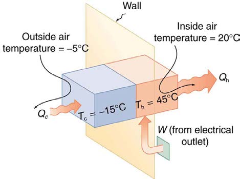
COP hp . (See Figure 15.30.) What is the best coefficient of performance possible for such a heat pump, if it has a hot reservoir temperature of 45.0ºC and a cold reservoir temperature of −15.0ºC ?
Strategy
A Carnot engine reversed will give the best possible performance as a heat pump. As noted above, COP hp = 1 / Eff , so that we need to first
calculate the Carnot efficiency to solve this problem.
Solution
Carnot efficiency in terms of absolute temperature is given by:
(15.38)
Eff C = 1 − T c
T .
h
The temperatures in kelvins are T h = 318 K and T c = 258 K , so that
(15.39)
Eff C = 1 − 258 K
318 K = 0.1887.
Thus, from the discussion above,
(15.40)
COP hp = 1
Eff =
1
0.1887 = 5.30 ,
or
(15.41)
COP hp = Q h
W = 5.30,
so that
Q
(15.42)
h = 5.30 W.
Discussion
This result means that the heat transfer by the heat pump is 5.30 times as much as the work put into it. It would cost 5.30 times as much for the
same heat transfer by an electric room heater as it does for that produced by this heat pump. This is not a violation of conservation of energy.
Cold ambient air provides 4.3 J per 1 J of work from the electrical outlet.
CHAPTER 15 | THERMODYNAMICS 529
Figure 15.30 Heat transfer from the outside to the inside, along with work done to run the pump, takes place in the heat pump of the example above. Note that the cold
temperature produced by the heat pump is lower than the outside temperature, so that heat transfer into the working fluid occurs. The pump’s compressor produces a
temperature greater than the indoor temperature in order for heat transfer into the house to occur.
Real heat pumps do not perform quite as well as the ideal one in the previous example; their values of COP hp range from about 2 to 4. This range
means that the heat transfer Q h from the heat pumps is 2 to 4 times as great as the work W put into them. Their economical feasibility is still
limited, however, since W is usually supplied by electrical energy that costs more per joule than heat transfer by burning fuels like natural gas.
Furthermore, the initial cost of a heat pump is greater than that of many furnaces, so that a heat pump must last longer for its cost to be recovered.
Heat pumps are most likely to be economically superior where winter temperatures are mild, electricity is relatively cheap, and other fuels are
relatively expensive. Also, since they can cool as well as heat a space, th