LabVIEW Graphical Programming by Serhat Beyenir - HTML preview
Download the book in PDF, ePub, Kindle for a complete version.
Chapter 2
Modular Programming
2.1 Modular Programming1
The power of LabVIEW lies in the hierarchical nature of the VI. After you create a VI, you can use it on the block diagram of another VI. There is no limit on the number of layers in the hierarchy. Using modular programming helps you manage changes and debug the block diagram quickly.
A VI within another VI is called a subVI. A subVI corresponds to a subroutine in text-based program-
ming languages. When you double-click a subVI, a front panel and block diagram appear, rather than a dialog box in which you can configure options. The front panel includes controls and indicators that might look familiar. The block diagram includes wires, front panel icons, functions, possibly subVIs, and other LabVIEW objects that also might look familiar.
The upper right corner of the front panel and block diagram displays the icon for the VI. This icon is the same as the icon that appears when you place the VI on the block diagram.
2.1.1 Icon and Connector Pane
After you build a front panel and block diagram, build the icon and the connector pane so you can
use the VI as a subVI. Every VI displays an icon, such as the one shown in this media, in the upper right corner of the front panel and block diagram windows. An icon is a graphical representation of a VI. It can contain text, images, or a combination of both. If you use a VI as a subVI, the icon identifies the subVI on the block diagram of the VI. You can double-click the icon to customize or edit it.
You also need to build a connector pane, shown in this media, to use the VI as a subVI. The
connector pane is a set of terminals that correspond to the controls and indicators of that VI, similar to the parameter list of a function call in text-based programming languages. The connector pane defines the inputs and outputs you can wire to the VI so you can use it as a subVI. A connector pane receives data at its input terminals and passes the data to the block diagram code through the front panel controls and receives the results at its output terminals from the front panel indicators.
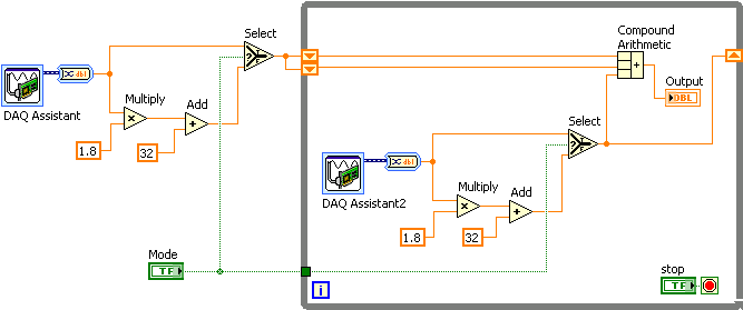
As you create VIs, you might find that you perform a certain operation frequently. Consider using
subVIs or loops to perform that operation repetitively. For example, the block diagram in Figure 2.1 contains two identical operations.
1This content is available online at <http://cnx.org/content/m12204/1.2/>.
Available for free at Connexions <http://cnx.org/content/col11408/1.1>
51
52
CHAPTER 2. MODULAR PROGRAMMING
Figure 2.1
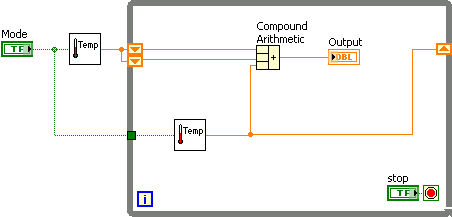
You can create a subVI that performs that operation and call the subVI twice. The example in Figure 2.2
calls the ❚❡♠♣❡r❛t✉r❡ VI as a subVI twice on its block diagram and functions the same as the previous block diagram.You also can reuse the subVI in other VIs. Refer to Repetition and Loops (Section 3.1) for more information about using loops to combine common operations.
Figure 2.2
Refer to the LabVIEW Basics II: Development Course Manual for more information about application
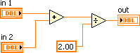
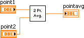
development. The following pseudo-code and block diagrams demonstrate the analogy between subVIs
and subroutines.
Function Code
Calling Program Code
continued on next page
Available for free at Connexions <http://cnx.org/content/col11408/1.1>

53
♠❛✐♥ ④ ❛✈❡r❛❣❡ ✭♣♦✐♥t✶✱ ♣♦✐♥t✷✱ ♣♦✐♥t❛✈❣✮
❢✉♥❝t✐♦♥ ❛✈❡r❛❣❡ ✭✐♥✶✱ ✐♥✷✱ ♦✉t✮ ④ ♦✉t ❂
⑥
✭✐♥✶ ✰ ✐♥✷✮✴✷✳✵❀ ⑥
SubVI Block Diagram
CallingVI Block Diagram
Table 2.1
2.2 Icons and Connector Panes2
After you build a VI front panel and block diagram, build the icon and the connector pane so you can use the VI as a subVI.
2.2.1 Creating an Icon
Every VI displays an icon, shown in this media, in the upper right corner of the front panel and
block diagram windows. An icon is a graphical representation of a VI. It can contain text, images, or a combination of both. If you use a VI as a subVI, the icon identifies the subVI on the block diagram of the VI.
The default icon contains a number that indicates how many new VIs you have opened since launching
LabVIEW. Create custom icons to replace the default icon by right-clicking the icon in the upper right corner of the front panel or block diagram and selecting ❊❞✐t ■❝♦♥ from the shortcut menu or double-clicking the icon in the upper right corner of the front panel. You also can edit icons by selecting ❋✐❧❡
❱■ Pr♦♣❡rt✐❡s
selecting ●❡♥❡r❛❧ from the ❈❛t❡❣♦r② pull-down menu, and clicking the ❊❞✐t ■❝♦♥ button.
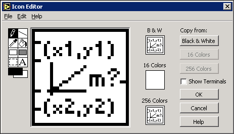
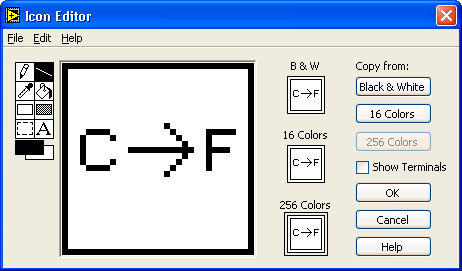
Use the tools on the left side of the ■❝♦♥ ❊❞✐t♦r dialog box to create the icon design in the editing area. The normal size image of the icon appears in the appropriate box to the right of the editing area, as shown in the dialog box in Figure 2.3.
2This content is available online at <http://cnx.org/content/m12205/1.2/>.
Available for free at Connexions <http://cnx.org/content/col11408/1.1>


54
CHAPTER 2. MODULAR PROGRAMMING
Figure 2.3
Depending on the type of monitor you use, you can design a separate icon for monochrome, 16-color,
and 256-color mode. LabVIEW uses the monochrome icon for printing unless you have a color printer.
Use the ❊❞✐t menu to cut, copy, and paste images from and to the icon. When you select a portion of
the icon and paste an image, LabVIEW resizes the image to fit into the selection area. You also can drag a graphic from anywhere in your file system and drop it in the upper right corner of the front panel or block diagram. LabVIEW converts the graphic to a 32 × 32 pixel icon.
Use the ❈♦♣② ❢r♦♠ option on the right side of the ■❝♦♥ ❊❞✐t♦r dialog box to copy from a color icon
to a black-and-white icon and vice versa. After you select a ❈♦♣② ❢r♦♠ option, click the ❖❑ button to complete the change.
NOTE:
If you do not draw a complete border around a VI icon, the icon background appears
transparent. When you select the icon on the block diagram, a selection marquee appears around
each individual graphic element in the icon.
Use the tools on the left side of the ■❝♦♥ ❊❞✐t♦r dialog box to create the icon design in the editing area. The normal size image of the icon appears in the appropriate box to the right of the editing area. The following tasks can be performed with these tools:
•
Use the P❡♥❝✐❧ tool to draw and erase pixel by pixel.
•
Use the ▲✐♥❡ tool to draw straight lines. To draw horizontal, vertical, and diagonal lines, press
the <❙❤✐❢t> key while you use this tool to drag the cursor.
•
Use the ❈♦❧♦r ❈♦♣② tool to copy the foreground color from an element in the icon.
•
Use the ❋✐❧❧ tool to fill an outlined area with the foreground color.
•
Use the ❘❡❝t❛♥❣❧❡ tool to draw a rectangular border in the foreground color. Double-click this
tool to frame the icon in the foreground color.
•
Use the ❋✐❧❧❡❞ ❘❡❝t❛♥❣❧❡ tool to draw a rectangle with a foreground color frame and filled
with the background color. Double-click this tool to frame the icon in the foreground color and fill it with the background color.
Available for free at Connexions <http://cnx.org/content/col11408/1.1>


55
•
Use the ❙❡❧❡❝t tool to select an area of the icon to cut, copy, move, or make other changes.
Double-click this tool and press the <❉❡❧❡t❡> key to delete the entire icon.
•
Use the ❚❡①t tool to enter text into the icon. Double-click this tool to select a different font.
✭❲✐♥❞♦✇s✮ The ❙♠❛❧❧ ❋♦♥ts option works well in icons.
•
Use the ❋♦r❡❣r♦✉♥❞✴❇❛❝❦❣r♦✉♥❞ tool to display the current foreground and background
colors. Click each rectangle to display a color palette from which you can select new colors.
• Use the options on the right side of the editing area to perform the following tasks:
Show Terminals - Displays the terminal pattern of the connector pane.
OK - Saves the drawing as the icon and returns to the front panel.
Cancel - Returns to the front panel without saving any changes.
• The menu bar in the ■❝♦♥ ❊❞✐t♦r dialog box contains more editing options such as ❯♥❞♦✱ ❘❡❞♦✱
❈✉t✱ ❈♦♣②✱ P❛st❡ , and ❈❧❡❛r .
2.2.2 Setting Up the Connector Pane
To use a VI as a subVI, you need to build a connector pane, shown in this media. The connector pane is a set of terminals that corresponds to the controls and indicators of that VI, similar to the parameter list of a function call in text-based programming languages. The connector pane defines the inputs and outputs you can wire to the VI so you can use it as a subVI.
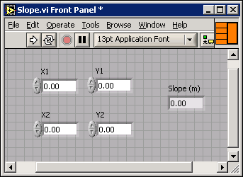
Define connections by assigning a front panel control or indicator to each of the connector pane terminals. To define a connector pane, right-click the icon in the upper right corner of the front panel window and select ❙❤♦✇ ❈♦♥♥❡❝t♦r from the shortcut menu. The connector pane replaces the icon. Each rectangle on the connector pane represents a terminal. Use the rectangles to assign inputs and outputs. The number of terminals LabVIEW displays on the connector pane depends on the number of controls and indicators on the front panel. The following front panel has four controls and one indicator, so LabVIEW displays four input terminals and one output terminal on the connector pane.
Figure 2.4
Available for free at Connexions <http://cnx.org/content/col11408/1.1>

56
CHAPTER 2. MODULAR PROGRAMMING
2.2.3 Selecting and Modifying Terminal Patterns
Select a different terminal pattern for a VI by right-clicking the connector pane and selecting P❛tt❡r♥s from the shortcut menu. Select a connector pane pattern with extra terminals. You can leave the extra terminals unconnected until you need them. This flexibility enables you to make changes with minimal effect on the hierarchy of the VIs. You also can have more front panel controls or indicators than terminals.
A solid border highlights the pattern currently associated with the icon. The maximum number of
terminals available for a subVI is 28.
The most commonly used pattern is shown in this media. This pattern is used as a standard to
assist in simplifying wiring. The top inputs and outputs are commonly used for passing references and the bottom inputs and outputs are used for error handling. Refer to the section on Clusters3 for more information about error handling.
NOTE: Try not to assign more than 16 terminals to a VI. Too many terminals can reduce the read-
ability and usability of the VI.
To change the spatial arrangement of the connector pane patterns, right-click the connector pane and select ❋❧✐♣ ❍♦r✐③♦♥t❛❧✱ ❋❧✐♣ ❱❡rt✐❝❛❧✱ ♦r ❘♦t❛t❡ ✾✵ ❉❡❣r❡❡s from the shortcut menu.
2.2.4 Assigning Terminals to Controls and Indicators
After you select a pattern to use for the connector pane, you must define connections by assigning a front panel control or indicator to each of the connector pane terminals. When you link controls and indicators to the connector pane, place inputs on the left and outputs on the right to prevent complicated, unclear wiring patterns in your VIs.
To assign a terminal to a front panel control or indicator, click a terminal of the connector pane, then click the front panel control or indicator you want to assign to that terminal. Click an open space on the front panel. The terminal changes to the data type color of the control to indicate that you connected the terminal.
You also can select the control or indicator first and then select the terminal.
NOTE: Although you use the ❲✐r✐♥❣ tool to assign terminals on the connector pane to front panel
controls and indicators, no wires are drawn between the connector pane and these controls and
indicators.
2.3 Convert C to F VI4
Exercise 2.3.1
Complete the following steps to create a VI that takes a number representing degrees Celsius and
converts it to a number representing degrees Fahrenheit.
2.3.1 Front Panel
1. Open a blank VI and begin building the following front panel.
3"Error Clusters" <http://cnx.org/content/m12231/latest/>
4This content is available online at <http://cnx.org/content/m12207/1.2/>.
Available for free at Connexions <http://cnx.org/content/col11408/1.1>


57
Figure 2.5
2. (Optional) Select ❲✐♥❞♦✇
❚✐❧❡ ▲❡❢t ❛♥❞ ❘✐❣❤t to display the front panel and block di-
agram side by side or ❲✐♥❞♦✇
❚✐❧❡ ❯♣ ❛♥❞ ❉♦✇♥ to display the front panel and block
diagram stacked.
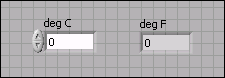
3. Create a numeric control. You will use this control to enter the value for degrees Celsius.
a. Select ❈♦♥tr♦❧s
◆✉♠❡r✐❝ ❈♦♥tr♦❧s to display the ◆✉♠❡r✐❝ ❈♦♥tr♦❧s palette. If
the ❈♦♥tr♦❧s palette is not visible, right-click an open space on the front panel
workspace to display it.
b.
Select the ◆✉♠❡r✐❝ ❈♦♥tr♦❧. Move the control to the front panel and click to
place the control.
c.
Type ❞❡❣ ❈ in the label of the control and press the <❊♥t❡r> key or click the ❊♥t❡r
button, shown in this media, on the toolbar. If you do not type the name immediately,
LabVIEW uses a default label.
NOTE: You can edit a label at any time by double-clicking the label, using the ▲❛❜❡❧✐♥❣ tool,
or right-clicking and selecting Pr♦♣❡rt✐❡s from the shortcut menu to display the property
dialog box.
4. Create a numeric indicator. You will use this indicator to display the value for degrees
Fahrenheit.
a.
Select the ◆✉♠❡r✐❝ ■♥❞✐❝❛t♦r located on the ❈♦♥tr♦❧s
◆✉♠❡r✐❝ ■♥❞✐❝❛t♦rs
palette.
b. Move the indicator to the front panel and click to place the indicator.
c. Type ❞❡❣ ❋ in the label and press the <❊♥t❡r> key or click the ❊♥t❡r button.
2.3.2 Block Diagram
1. Display the block diagram by clicking it or by selecting ❲✐♥❞♦✇
❙❤♦✇ ❇❧♦❝❦ ❉✐❛❣r❛♠.
LabVIEW creates corresponding control and indicator terminal icons on the block diagram
when you place controls and indicators on the front panel. The terminals represent the data
type of the control or indicator. You should see two double-precision, floating-point termi-
nals on the block diagram, one indicator, and one control.
NOTE: Control terminals have a thicker border than indicator terminals.
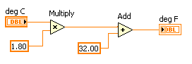
2.
Place
the
▼✉❧t✐♣❧② function, located on the ❋✉♥❝t✐♦♥s ❆r✐t❤♠❡t✐❝ ✫
❈♦♠♣❛r✐s♦♥ ❊①♣r❡ss ◆✉♠❡r✐❝ palette, on the block diagram to the right of the ❞❡❣
❈ indicator. If the ❋✉♥❝t✐♦♥s palette is not visible, right-click an open space on the block
diagram workspace to display it.
Available for free at Connexions <http://cnx.org/content/col11408/1.1>


58
CHAPTER 2. MODULAR PROGRAMMING
3.
Place
the
❆❞❞
function,
located
on
the
❋✉♥❝t✐♦♥s ❆r✐t❤♠❡t✐❝ ✫
❈♦♠♣❛r✐s♦♥ ❊①♣r❡ss ◆✉♠❡r✐❝ palette, on the block diagram to the right of the ▼✉❧t✐♣❧②
function.
4.
Place
a
◆✉♠❡r✐❝ ❈♦♥st❛♥t,
located
on
the
❋✉♥❝t✐♦♥s ❆r✐t❤♠❡t✐❝ ✫
❈♦♠♣❛r✐s♦♥ ❊①♣r❡ss ◆✉♠❡r✐❝ palette, to the lower left of the ▼✉❧t✐♣❧② function.
Type ✶✳✽✵ in the constant. When you first place a numeric constant, it is highlighted so
you can type a value. If the constant is no longer highlighted, double-click the constant to
activate the ▲❛❜❡❧✐♥❣ tool.
5.
Place
a
◆✉♠❡r✐❝ ❈♦♥st❛♥t,
located
on
the
❋✉♥❝t✐♦♥s ❆r✐t❤♠❡t✐❝ ✫
❈♦♠♣❛r✐s♦♥ ❊①♣r❡ss ◆✉♠❡r✐❝ palette, to the left of the ❆❞❞ function. Type ✸✷✳✵ in
the constant.
6.
Use the ❲✐r✐♥❣ tool, shown in this media, to wire the icons as shown in Figure 2.6.
Figure 2.6
• To wire from one terminal to another, use the ❲✐r✐♥❣ tool to click the first terminal,
move the tool to the second terminal, and click the second terminal. You can start
wiring at either terminal.
• You can bend a wire by clicking to tack down the wire and moving the cursor in a
perpendicular direction. Press the s♣❛❝❡❜❛r to toggle the wire direction.
• To identify terminals on the nodes, right-click the ▼✉❧t✐♣❧② and ❆❞❞ functions and
select ❱✐s✐❜❧❡ ■t❡♠s
❚❡r♠✐♥❛❧s from the shortcut menu to display the connector
pane on the block diagram. Return to the icons after wiring by right-clicking the func-
tions and selecting ❱✐s✐❜❧❡ ■t❡♠s
❚❡r♠✐♥❛❧s from the shortcut menu to remove
the checkmark.
• When you move the ❲✐r✐♥❣ tool over a terminal, the terminal area blinks, indicating
that clicking will connect the wire to that terminal and a tip strip appears, displaying
the name of the terminal. If the ❈♦♥t❡①t ❍❡❧♣ window is open, the terminal area also
blinks in the ❈♦♥t❡①t ❍❡❧♣ window.
• To cancel a wire you started, press the <❊s❝> key, right-click, or click the terminal
where you started the wire.
7. Display the front panel by clicking it or by selecting ❲✐♥❞♦✇
❙❤♦✇ ❋r♦♥t P❛♥❡❧.
8. Save the VI as ❈♦♥✈❡rt ❈ t♦ ❋✳✈✐ in the ❈✿\❊①❡r❝✐s❡s\▲❛❜❱■❊❲ ❇❛s✐❝s ■ directory.
2.3.3 Run the VI
1. Enter a number in the numeric control and run the VI.
Available for free at Connexions <http://cnx.org/content/col11408/1.1>


59
a.
Use the ❖♣❡r❛t✐♥❣ tool, shown in this media, or the ▲❛❜❡❧✐♥❣ tool to double-click
the numeric control and type a new number.
b.
Click the ❘✉♥ button, shown at left, to run the VI.
c. Try several different numbers and run the VI again.
2.3.4 Icon and Connector Pane
1. Right-click the icon in the upper right corner of the front panel window and select ❊❞✐t
■❝♦♥ from the shortcut menu. The ■❝♦♥ ❊❞✐t♦r dialog box appears.
2.
Double-click the ❙❡❧❡❝t tool, shown in this media, on the left side of the ■❝♦♥ ❊❞✐t♦r
dialog box to select the default icon.
3. Press the <❉❡❧❡t❡> key to remove the default icon.
4.
Double-click the ❘❡❝t❛♥❣❧❡ tool, shown in this media, to redraw the border.
5. Create the icon in Figure 2.7.
Figure 2.7
a.
Double-click the ❚❡①t tool, shown in this media, and change the font to ❙♠❛❧❧
❋♦♥ts .
b. Use the ❚❡①t tool to click the editing area where you will begin typing.
c. Type ❈ and ❋. While the text is active, you can move the text by pressing the arrow keys.
d.
Use the P❡♥❝✐❧ tool, shown in this media, to create the arrow.
NOTE: To draw horizontal or vertical straight lines, press the <❙❤✐❢t> key while you
use the P❡♥❝✐❧ tool to drag the cursor.
e. Use the ❙❡❧❡❝t tool and the arrow keys to move the text and arrow you created.
f. Select the ❇ ✫ ❲ icon and click the ✷✺✻ ❈♦❧♦rs button in the ❈♦♣② ❢r♦♠ section
to create a black and white icon, which LabVIEW uses for printing unless you have a
color printer.
Available for free at Connexions <http://cnx.org/content/col11408/1.1>

60
CHAPTER 2. MODULAR PROGRAMMING
g. Select the ✶✻ ❈♦❧♦rs icon and click the ✷✺✻ ❈♦❧♦rs button in the ❈♦♣② ❢r♦♠ sec-
tion.
h. When you complete the icon, click the ❖❑ button to close the ■❝♦♥ ❊❞✐t♦r dialog
box. The icon appears in the upper right corner of the front panel and block diagram.
6.
Right-click the icon on the front panel and select ❙❤♦✇ ❈♦♥♥❡❝t♦r from the shortcut
menu to define the connector pane terminal pattern. LabVIEW selects a default connector
pane pattern based on the number of controls and indicators on the front panel. For example,
this front panel has two terminals, ❞❡❣ ❈ and ❞❡❣ ❋ , so LabVIEW selects a connector
pane pattern with two terminals, shown in this media.
7. Assign the terminals to the numeric control and numeric indicator.
a. Select ❍❡❧♣
❙❤♦✇ ❈♦♥t❡①t ❍❡❧♣ to display the ❈♦♥t❡①t ❍❡❧♣ window.
b. Click the left terminal in the connector pane. The tool automatically changes to the
❲✐