Hydraulics by Department of the Army - HTML preview
Download the book in PDF, ePub, Kindle for a complete version.
inside diameter of a female fitting.
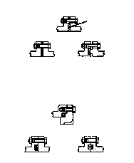
Figure 2-38 shows the assembly of a
clamp-type coupling. If you use this coupling,
do not skive the hose. Lubricate the ID of a
hose and the OD of a stem. Clamp a hose stem
in a bench vice and install a hose. Turn the
hose counterclockwise until it bottoms against
the shoulder of the stem (Figure 2-38, diagram
A). If you do not have a vice, force the stem
A
into the hose by pushing or striking the stem
with a wooden block. Place the clamp halves in
position (Figure 2-38, diagram B) and draw
them together with a vice or with extra long
bolts until the standard bolts protrude far
enough to grip the nuts. Remove the extra long
bolts and place retaining bolts through the
clamp. Tighten the nuts until you get the
required torque (Figure 2-38, diagram C).
NOTE: You may have to
retighten the bolts after the
hose assembly has been operat-
ing about 10 to 20 hours. Use
clamp-type couplings on hose
B
assemblies with diameters of 1
inch or greater. Use reusable
screw-type fittings on hose
assemblies with diameters less
than 1 inch.
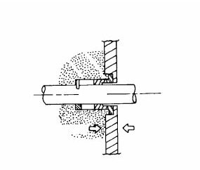
2-11. Leakage. Any hydraulic system will
have a certain amount of leakage. Any leakage
will reduce efficiency and cause power loss.
Some leakage is built in (planned), some is not.
Leakage may be internal, external, or both.
a. Internal. This type of leakage (nonposi-
tive) must be built into hydraulic components
C
to lubricate valve spools, shafts, pistons, bear-
ings, pumping mechanisms, and other moving
parts. In some hydraulic valves and pump and
motor compensator controls, leakage paths are
Figure 2-38. Assembly of clamp-type
built in to provide precise control and to avoid
coupling
hunting (oscillation) of spools and pistons. Oil
is not lost in internal leakage; it returns to a reservoir through return lines or specially provided drain passages.
Too much internal leakage will slow down actuators. The power loss is accompanied by
the heat generated at a leakage path. In some instances, excess leakage in a valve could
cause a cylinder to drift or even creep when a valve is supposedly in neutral. In the case of Hydraulic Systems
2-29
FM 5-499
flow or pressure-control valves, leakage can often reduce effective control or even cause control to be lost.
Normal wear increases internal leakage, which provides larger flow paths for the leak-
ing oil. An oil that is low in viscosity leaks more readily than a heavy oil. Therefore an oil’s viscosity and viscosity index are important considerations in providing or preventing internal leakage. Internal leakage also increases with pressure, just as higher pressure causes a greater flow through an orifice. Operating above the recommended pressures adds the danger of excessive internal leakage and heat generation to other possible harmful effects.
A blown or ruptured internal seal can open a large enough leakage path to divert all of a
pump's delivery. When this happens, everything except the oil flow and heat generation at a
leakage point can stop.
b. External. External leakage can be hazardous, expensive, and unsightly. Faulty
installation and poor maintenance are the prime causes of external leakage. Joints may
leak because they were not put together properly or because shock and vibration in the lines
shook them loose. Adding supports to the lines prevents this. If assembled and installed
correctly, components seldom leak. However, failure to connect drain lines, excessive pres-
sures, or contamination can cause seals to blow or be damaged, resulting in external leakage
from the components.
c. Prevention. Proper installation, control of operating conditions, and proper maintenance help prevent leakage.
(1) Installation. Installing piping and tubing according to a manufacturer's recommen-
dations will promote long life of external seals. Vibration or stresses that result from
improper installation can shake loose connections and create puddles. Avoid pinching, cock-
ing, or incorrectly installing seals when assembling the units. Use any special tools that the manufacturer recommends for installing the seals.
(2) Operating Conditions. To ensure correct seal life, you must control the operating
conditions of the equipment. A shaft seal or piston-rod seal exposed to moisture, salt, dirt, or any other abrasive contaminate will have a shortened life span. Also, operators should
always try to keep their loads within the recommended limits to prevent leakage caused by
excessive pressures.
(3) Maintenance. Regular filter and oil changes, using a high-quality hydraulic oil, add
to seal life. Using inferior oil could wear on a seal and interfere with desirable oil properties.
Proper maintenance prevents impurity deposits and circulating ingredients that could wear
on a dynamic seal.
Never use additives without approval from the equipment and oil suppliers. Lubrica-
tion can be critical to a seal's life in dynamic applications. Synthetics do not absorb much oil and must be lubricated quickly or they will rub. Leather and fiber do absorb oil. Manufacturers recommend soaking a seal overnight in oil before installing it. Do not install a seal dry. Always coat it in clean hydraulic oil before installing it.
2-12. Seals. Seals are packing materials used to prevent leaks in liquid-powered systems.
A seal is any gasket, packing, seal ring, or other part designed specifically for sealing. Sealing applications are usually static or dynamic, depending if the parts being sealed move in
relation to one another. Sealing keeps the hydraulic oil flowing in passages to hold pressure and keep foreign materials from getting into the hydraulic passages. To prevent leakage,
2-30
Hydraulic Systems
FM 5-499
use a positive sealing method, which
involves using actual sealing parts or
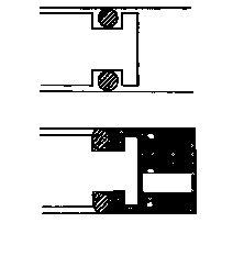
BASIC FLANGE JOINTS
materials. In most hydraulic compo-
nents, you can use nonpositive sealing
(leakage for lubrication) by fitting the
Gasket
parts closely together. The strength
of an oil film that the parts slide
Simple
against provides an effective seal.
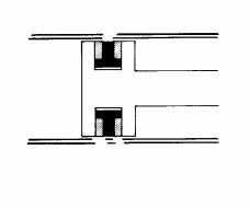
a. Static Seals. Pipe-threaded
Tongue-and groove
Tongue-and groove
seals, seal rings used with tube fit-
tings, valve end-cap seals, and other
seals on nonmoving parts are static
seals. Mounting gaskets and seals
METAL-TO-METAL JOINTS
are static, as are seals used in making
connections between components. A
static seal or gasket is placed between
parts that do not move in relation to
each other. Figure 2-39 shows some
typical static seals in flanged connec-
tions.
b. Dynamic Seals. In a dynamic
sealing application, either a recipro-
Figure 2-39. Static seals
cating or a rotary motion occurs between the two
parts being sealed; for example, a piston-to-bar-
rel seal in a hydraulic cylinder or a drive-shaft
seal in a pump or motor.
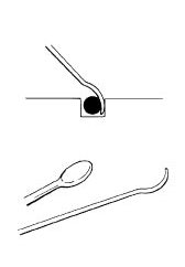
(1) O-Ring (Figure 2-40). An O-ring is a
positive seal that is used in static and dynamic
No
applications. It has replaced the flat gasket on
pressure
hydraulic equipment. When being installed,
an O-ring is squeezed at the top and bottom in
its groove and against the mating part. It is
capable of sealing very high pressure. Pressure
forces the seal against the side of its groove,
and the result is a positive seal on three sides.
Dynamic applications of an O-ring are usually
limited to reciprocating parts that have rela-
tively short motion.
Pressure
To remove an O-ring seal, you need a spe-
cial tool made of soft iron or aluminum or a
brass rod (Figure 2-41, page 2-32). Make sure
that the tool’s edges are flat and that you polish
any burrs and rough surfaces.
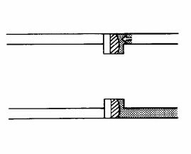
(2) Backup Ring (Figure 2-42, page 2-32).
Usually, made of stiff nylon, you can use a
Figure 2-40. O-ring placement
backup ring with an O-ring so that it is not
Hydraulic Systems
2-31
FM 5-499
forced into the space between the mating
parts. A combination of high pressure and
Surface must be smooth and
free from scratches.
clearance between the parts could call for a
backup ring.
Corners must not be dented
or bumped.
(3) Lathe-Cut Seal. This seal is like an O-
0.005 radius desired.
ring but is square in cross-section rather than
round. A lathe-cut ring is cut from extruded
tubes, while an O-ring must be individually
molded. In many static applications, round-
and square-section seals are interchangeable, if
made from the same material.
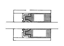
(4) T-Ring Seal (Figure 2-43). This seal is
reinforced with back-up rings on each side. A T-
ring seal is used in reciprocating dynamic appli-
cations, particularly on cylinder pistons and
around piston rods.
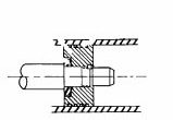
(5) Lip Seal (Figure 2-44). This a dynamic
Flatten as shown and polish
seal used mainly on rotating shafts. A sealing
off burrs and edges.
lip provides a positive seal against low pres-
sure. A lip is installed toward the pressure
source. Pressure against a lip balloons it out to
aid in sealing. Very high pressure, however,
can get past this kind of seal because it does not
Figure 2-41. O-ring removal tool
have the backup support that an O-ring has.
Sometimes, double-lip seals are
used on the shafts of reversible pumps
or motors. Reversing a unit can give
O ring
an alternating pressure and vacuum
condition in the chamber adjacent to a
seal. A double-lip seal, therefore, pre-
Pressure
vents oil from getting out or air and
dirt from getting in.
(6) Cup Seal (Figure 2-45). This is
a positive seal that is used on hydraulic
cylinder pistons and seals much like a
lip seal. A cup seal is backed up so that
it can handle very high pressures.
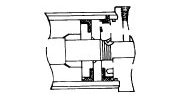
(7) Piston Ring (Figure 2-46). A
piston ring is used to seal pressure at
Back-up ring
the end of a reciprocating piston. It
helps keep friction at a minimum in a
hydraulic cylinder and offers less resis-
tance to movement than a cup seal. A
piston ring is used in many complex
components and systems to seal fluid
Figure 2-42. Backup ring
passages leading from hollow rotating
2-32
Hydraulic Systems
FM 5-499
Seal
Seal housing
Spring
lip
High
pressure
Back-up ring
Figure 2-43. T-ring seal
Figure 2-44. Lip seal
Seal ring
Cylinder
Piston
barrel
Cup seals
O ring
Cylinder
Piston
Figure 2-45. Cup seal
Figure 2-46. Piston ring
shafts. It is fine for high pressures but may not provide a positive seal. A positive seal is more likely to occur when piston rings are placed side by side. Often, a piston ring is
designed to allow some leakage for lubrication.
(8) Face Seal (Figure 2-47, page 2-34). This seal has two smooth, flat elements that run
together to seal a rotating shaft. One element is metallic and the other is nonmetallic. The elements are attached to a shaft and a body so that one face is stationary and the other turns against it. One element is often spring-loaded to take up wear. A face seal is used primarily when there is high speed, pressure, and temperature.
c. Packing. Packing is a type of twisted or woven fiber or soft metal strands that are packed between the two parts being sealed. A packing gland supports and backs up the
packing. Packing (Figure 2-48) can be either static or dynamic. It has been and is used as a rotating shaft seal, a reciprocating piston-rod seal, and a gasket in many static applications.
In static applications, a seal is replacing a packing. A compression packing is usually
placed in a coil or layered in a bore and compressed by tightening a flanged member. A
molded packing is molded into a precise cross-sectional form, such as a U or V. Several Hydraulic Systems
2-33

FM 5-499
packings can be used together, with a backup
that is spring-loaded to compensate for wear.
Housing
d. Seal Materials. The earliest sealing
materials for hydraulic components were
Sealing face
mainly leather, cork, and impregnated fibers.
Currently, most sealing materials in a hydrau-
Preloading
lic system are made from synthetic materials
spring
such as nitrile, silicone, and neoprene.
(1) Leather Seals. Leather is still a good
Shaft
sealing material and has not been completely
replaced by elastomers. It is tough, resists
abrasion, and has the ability to hold lubricat-
Low pressure
ing fluids in its fibers. Impregnating leather
High pressure
with synthetic rubber improves the leather's
sealing ability and reduces its friction.
Leather's disadvantages are that it tends to
squeal when it is dry, and it cannot stand high
temperatures.
Figure 2-47. Face seal
(2) Nitrile Seals. Nitrile is a compara-
tively tough material with excellent wearabil-
ity. Its composition varies to be compatible
with petroleum oils, and it can easily be
Compression
molded into different seal shapes. Some
packings
nitrile seals can be used, without difficulty, in
temperatures ranging from -40 degrees Fahr-
enheit to +230° F.
Pressure
(3) Silicone Seals. Silicone is an elas-
tomer that has a much wider temperature
range than some nitrile seals have. Silicone
cannot be used for reciprocating seals because
it is not as tough. It tears, elongates, and
abrades fairly easily. Many lip-type shaft
seals made from silicone are used in extreme
temperature applications. Silicone O-rings are
Figure 2-48. Compression packing
used for static applications. Silicone has a ten-
dency to swell since it absorbs a fair volume of
oil while running hot. This is an advantage, if
the swelling is not objectionable, because a seal can run dry for a longer time at start-up.
(4) Neoprene. At very low temperatures, neoprene is compatible with petroleum oil.
Above 150 degrees, it has a habit of cooking or vulcanizing, making it less useful.
(5) Nylon. Nylon is a plastic (also known as fluoro-elastomer) that combines fluorine
with a synthetic rubber. It is used for backup rings, has sealing materials in special applications, and has a very high heat resistance.
2-34
Hydraulic Systems
FM 5-499
CHAPTER 3
Pumps
Hydraulic pumps convert mechanical energy from a prime mover (engine or electric
motor) into hydraulic (pressure) energy. The pressure energy is used then to operate an actuator. Pumps push on a hydraulic fluid and create flow.
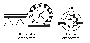
3-1. Pump Classifications. All pumps create flow. They operate on the displacement principle. Fluid is taken in and displaced to another point. Pumps that discharge liquid in a continuous flow are nonpositive-displacement type. Pumps that discharge volumes of liquid
separated by periods of no discharge are positive-displacement type.
a. Nonpositive-Displacement Pumps. With this pump, the volume of liquid delivered for each cycle depends on the resistance offered to flow. A pump produces a force on the liquid
that is constant for each particular speed of the pump. Resistance in a discharge line pro-
duces a force in the opposite direction. When these forces are equal, a liquid is in a state of equilibrium and does not flow.
If the outlet of a nonpositive-displacement pump is completely closed, the discharge
pressure will rise to the maximum for a pump operating at a maximum speed. A pump will
churn a liquid and produce heat. Figure 3-1 shows a nonpositive-displacement pump. A
water wheel picks up the fluid and moves it.
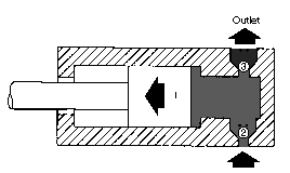
b. Positive-Displacement Pumps. With this pump, a definite volume of liquid is delivered for each cycle of pump operation, regardless of resistance, as long as the capacity of the power unit driving a pump is not exceeded. If an outlet is completely closed, either the unit driving a pump will stall or something will break. Therefore, a positive-displacement-type
pump requires a pressure regulator or pressure-relief valve in the system. Figure 3-2, page
3-2, shows a reciprocating-type, positive-displacement pump.
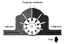
Figure 3-3, page 3-2, shows
another positive-displacement
pump. This pump not only creates
flow, but it also backs it up. A
sealed case around the gear traps
the fluid and holds it while it
moves. As the fluid flows out of
the other side, it is sealed against
backup. This sealing is the posi-
tive part of displacement. With-
out it, the fluid could never
overcome the resistance of the
other parts in a system.
c. Characteristics. The three
Figure 3-1. Nonpositive-displacement pump
contrasting characteristics in the
Pumps
3-1
FM 5-499
operation of positive- and nonpositive-displacement pumps are as follows:
•
Nonpositive-displacement pumps provide a smooth, continuous flow; positive-
displacement pumps have a pulse with each stroke or each time a pumping cham-
ber opens to an outlet port.
•
Pressure can reduce a nonpositive pump’s delivery. High outlet pressure can
stop any output; the liquid simply recirculates inside the pump. In a positive-
displacement pump, pressure affects the output only to the extent that it
increases internal leakage.
•
Nonpositive-displacement pumps, with the inlets and outlets connected hydrauli-
cally, cannot create a vacuum sufficient for self-priming; they must be started
with the inlet line full of liquid and free of air. Positive-displacement pumps often
are self-priming when started properly.
3-2. Performance. Pumps are usually rated according to their volumetric output and pressure. Volumetric output (delivery rate or capacity) is the amount of liquid that a pump can
deliver at its outlet port per unit of time at a given drive speed, usually expressed in GPM or cubic inches per minute. Because changes in pump drive affect volumetric output, pumps
are sometimes rated according to displace-
ment, that is the amount of liquid that
they can deliver per cycle or cubic inches
per revolution.
Pressure is the force per unit area of a
liquid, usually expressed in psi. (Most of
the pressure in the hydraulic systems cov-
ered in this manual is created by resis-
tance to flow.) Resistance is usually
caused by a restriction or obstruction in a
path or flow. The pressure developed in a
system has an effect on the volumetric
output of the pump supplying flow to a
system. As pressure increases, volumetric
Figure 3-2. Reciprocating-type, positive-
output decreases. This drop in output is
displacement pump
caused by an increase in internal leakage
(slippage) from a pump's outlet side to its
inlet side. Slippage is a measure of a
pump’s efficiency and usually is expressed
in percent. Some pumps have greater
internal slippage than others; some
pumps are rated in terms of volumetric
output at a given pressure.
3-3. Displacement. Displacement is the
amount of liquid transferred from a
pump’s inlet to its outlet in one revolution
or cycle. In a rotary pump, displacement
is expressed in cubic inches per revolution
and in a reciprocating pump in cubic
inches per cycle. If a pump has more than
Figure 3-3. Positive-displacement pump
3-2
Pumps
FM 5-499
one pumping chamber, its displacement is equal to the displacement of one chamber multi-
plied by the number of chambers. Displacement is either fixed or variable.
a. Fixed-Displacement Pump. In this pump, the GPM output can be changed only by
varying the drive speed. The pump can be used in an open-center system—a pump’s output
has a free-flow path back to a reservoir in the neutral condition of a circuit.
b. Variable-Displacement Pump. In this pump, pumping-chamber sizes can be changed.
The GPM delivery can be changed by moving the displacement control, changing the drive
speed, or doing both. The pump can be used in a closed-center system—a pump continues to
ope