Hydraulics by Department of the Army - HTML preview
Download the book in PDF, ePub, Kindle for a complete version.
F
A
C
B
Figure 1-9. Effect of friction on pressure
Hydraulic Basics
1-7
FM 5-499
90 psi
100 psi
100 psi
X
Chamber A
Chamber B
100 psi
Passage C
Figure 1-10. Bernouilli’s Principle
static pressure of a moving liquid varies inversely with its velocity; that is, as velocity
increases, static pressure decreases. In the figure, the force on piston X is sufficient to create a pressure of 100 psi on chamber A. As piston X moves down, the liquid that is forced out of chamber A must pass through passage C to reach chamber B. The velocity increases as it
passes through C because the same quantity of liquid must pass through a narrower area in
the same time. Some of the 100 psi static pressure in chamber A is converted into velocity
energy in passage C so that a pressure gauge at this point registers 90 psi. As the liquid
passes through C and reaches chamber B, velocity decreases to its former rate, as indicated
by the static pressure reading of 100 psi, and some of the kinetic energy is converted to
potential energy.
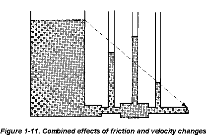
Figure 1-11 shows the combined effects of friction and velocity changes. As in Figure 1-9,
page 1-7, pressure drops from maximum at C to zero at B. At D, velocity is increased, so the pressure head decreases. At E, the head increases as most of the kinetic energy is given up
to pressure energy because velocity is decreased. At F, the head drops as velocity increases.
e. Work. To do work in a hydraulic system, flow must be present. Work, therefore,
exerts a force over a definite distance. It is a measure of force multiplied by distance.
f. Power. The standard unit of power is horsepower (hp). One hp is equal to 550 ft lb of work every second. Use the following equation to find power:
P = f x d/t
where—
P = power, in hp
f = force, in GPM
d = distance, in psi
t = time (1,714)
1-8
Hydraulic Basics
FM 5-499
D
E
F
A
B
C
Figure 1-11. Combined effects of friction and velocity changes
Hydraulic Basics
1-9
FM 5-499
CHAPTER 2
Hydraulic Systems
A hydraulic system contains and confines a liquid in such a way that it uses the laws
governing liquids to transmit power and do work. This chapter describes some basic systems and discusses components of a hydraulic system that store and condition the fluid. The oil reservoir (sump or tank) usually serves as a storehouse and a fluid conditioner. Filters, strainers, and magnetic plugs condition the fluid by removing harmful impurities that could clog passages and damage parts. Heat exchanges or coolers often are used to keep the oil temperature within safe limits and prevent deterioration of the oil. Accumulators, though technically sources of stored energy, act as fluid storehouses.
2-1. Basic Systems. The advantages of hydraulic systems over other methods of power transmission are—
• Simpler design. In most cases, a few pre-engineered components will replace compli-
cated mechanical linkages.
• Flexibility. Hydraulic components can be located with considerable flexibility. Pipes
and hoses in place of mechanical elements virtually eliminate location problems.
• Smoothness. Hydraulic systems are smooth and quiet in operation. Vibration is kept
to a minimum.
• Control. Control of a wide range of speed and forces is easily possible.
• Cost. High efficiency with minimum friction loss keeps the cost of a power transmis-
sion at a minimum.
• Overload protection. Automatic valves guard the system against a breakdown from
overloading.
The main disadvantage of a hydraulic system is maintaining the precision parts when
they are exposed to bad climates and dirty atmospheres. Protection against rust, corrosion,
dirt, oil deterioration, and other adverse environment is very important. The following
paragraphs discuss several basic hydraulic systems.
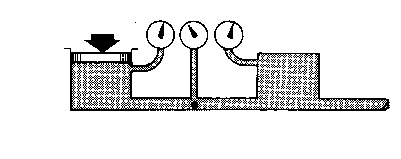
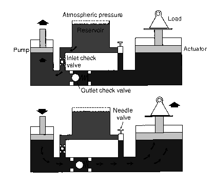
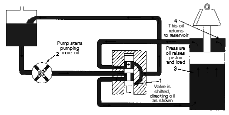
a. Hydraulic Jack. In this system (Figure 2-1, page 2-2), a reservoir and a system of valves has been added to Pascal's hydraulic lever to stroke a small cylinder or pump continuously and raise a large piston or an actuator a notch with each stroke. Diagram A shows
an intake stroke. An outlet check valve closes by pressure under a load, and an inlet check
valve opens so that liquid from the reservoir fills the pumping chamber. Diagram B shows
the pump stroking downward. An inlet check valve closes by pressure and an outlet valve
opens. More liquid is pumped under a large piston to raise it. To lower a load, a third valve (needle valve) opens, which opens an area under a large piston to the reservoir. The load
then pushes the piston down and forces the liquid into the reservoir.
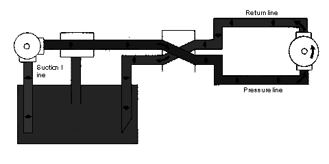
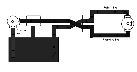
b. Motor-Reversing System. Figure 2-2, page 2-3, shows a power-driven pump operating a reversible rotary motor. A reversing valve directs fluid to either side of the motor and back Hydraulic Systems
2-1
FM 5-499
Figure 2-1. Hydraulic jack
to the reservoir. A relief valve protects the system against excess pressure and can bypass
pump output to the reservoir, if pressure rises too high.
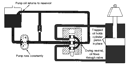
c. Open-Center System. In this system, a control-valve spool must be open in the center to allow pump flow to pass through the valve and return to the reservoir. Figure 2-3, page
2-4, shows this system in the neutral position. To operate several functions simultaneously, an open-center system must have the correct connections, which are discussed below. An
open-center system is efficient on single functions but is limited with multiple functions.
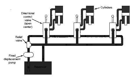
(1) Series Connection. Figure 2-4, page 2-4, shows an open-center system with a series
connection. Oil from a pump is routed to the three control valves in series. The return from the first valve is routed to the inlet of the second, and so on. In neutral, the oil passes
through the valves in series and returns to the reservoir, as the arrows indicate. When a
control valve is operated, the incoming oil is diverted to the cylinder that the valve serves.
Return liquid from the cylinder is directed through the return line and on to the next valve.
This system is satisfactory as long as only one valve is operating at a time. When this
happens, the full output of the pump at full system pressure is available to that function.
However, if more than one valve is operating, the total of the pressures required for each
function cannot exceed the system’s relief setting.
2-2
Hydraulic Systems
FM 5-499
Figure 2-2. Motor-reversing system
Hydraulic Systems
2-3
FM 5-499
Figure 2-3. Open-center system
Figure 2-4. Open-center system with a series connection
2-4
Hydraulic Systems
FM 5-499
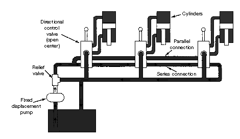
(2) Series/Parallel Connection. Figure 2-5 shows a variation on the series-connected
type. Oil from the pump is routed through the control valves in series, as well as in parallel.
The valves are sometimes stacked to allow for extra passages. In neutral, a liquid passes
through the valves in series, as the arrows indicate. However, when any valve is operating,
the return is closed and the oil is available to all the valves through the parallel connection.
When two or more valves are operated at once, the cylinder that needs the least pressure
will operate first, then the cylinder with the next least, and so on. This ability to operate two or more valves simultaneously is an advantage over the series connection.
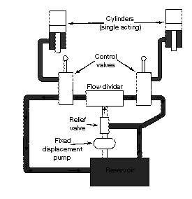
(3) Flow Divider. Figure 2-6, page 2-6, shows an open-center system with a flow divider.
A flow divider takes the volume of oil from a pump and divides it between two functions. For example, a flow divider might be designed to open the left side first in case both control
valves were actuated simultaneously. Or, it might divide the oil to both sides, equally or by percentage. With this system, a pump must be large enough to operate all the functions
simultaneously. It must also supply all the liquid at the maximum pressure of the highest
function, meaning large amounts of HP are wasted when operating only one control valve.
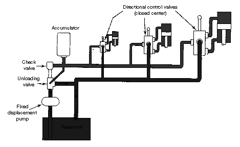
d. Closed-Center System. In this system, a pump can rest when the oil is not required to operate a function. This means that a control valve is closed in the center, stopping the flow of the oil from the pump. Figure 2-7, page 2-6, shows a closed-center system. To operate several functions simultaneously, a closed-center system have the following connections:
(1) Fixed-Displacement Pump and Accumulator. Figure 2-8, page 2-7, shows a closed-
center system. In this system, a pump of small but constant volume charges an accumulator.
Figure 2-5. Open-center system with a series/parallel connection
Hydraulic Systems
2-5
FM 5-499
Figure 2-6. Open-center system with a flow divider
Figure 2-7. Closed-center system
2-6
Hydraulic Systems
FM 5-499
Figure 2-8. Fixed-displacement pump and accumulator
When an accumulator is charged to full pressure, an unloading valve diverts the pump flow
back to a reservoir. A check valve traps the pressured oil in the circuit.
When a control valve is operated, an accumulator discharges its oil and actuates a cylin-
der. As pressure begins to drop, an unloading valve directs the pump flow to an accumulator
to recharge the flow. This system, using a small capacity pump, is effective when operating
oil is needed only for a short time. However, when the functions need a lot of oil for longer periods, an accumulator system cannot handle it unless the accumulator is very large.
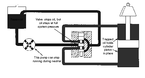
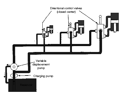
(2) Variable-Displacement Pump. Figure 2-9, page 2-8, shows a closed-center system
with a variable-displacement pump in the neutral mode. When in neutral, oil is pumped
until the pressure rises to a predetermined level. A pressure-regulating valve allows the
pump to shut off by itself and maintain this pressure to the valve. When the control valve is operating, oil is diverted from the pump to the bottom of a cylinder. The drop in pressure
caused by connecting the pump’s pressure line to the bottom of the cylinder causes the pump
to go back to work, pumping oil to the bottom of the piston and raising the load.
When the valve moves, the top of the piston connects to a return line, which allows the
return oil that was forced from the piston to return to the reservoir or pump. When the valve returns to neutral, oil is trapped on both sides of the cylinder, and the pressure passage from the pump is dead-ended. After this sequence, the pump rests. Moving the spool in the downward position directs oil to the top of the piston, moving the load downward. The oil from the bottom of the piston is sent into the return line.
Figure 2-10, page 2-8, shows this closed-center system with a charging pump, which
pumps oil from the reservoir to the variable-displacement pump. The charging pump supplies
Hydraulic Systems
2-7
FM 5-499
Figure 2-9. Variable-displacement pump
Figure 2-10. Closed-center system with charging pump
2-8
Hydraulic Systems
FM 5-499
only the makeup oil required in a system and provides some inlet pressure to make a variable-
displacement pump more efficient. The return oil from a system's functions is sent directly
to the inlet of a variable-displacement pump.
Because today’s machines need more hydraulic power, a closed-center system is more
advantageous. For example, on a tractor, oil may be required for power steering, power
brakes, remote cylinders, three-point hitches, loaders, and other mounted equipment. In
most cases, each function requires a different quantity of oil. With a closed-center system, the quantity of oil to each function can be controlled by line or valve size or by orificing with less heat build up when compared to the flow dividers necessary in a comparable open-center
system. Other advantages of a closed-center system are as follows:
• It does not require relief valves because the pump simply shuts off by itself when
standby pressure is reached. The prevents heat buildup in systems where relief
pressure is frequently reached.
• The size of the lines, valves, and cylinders can be tailored to the flow requirements
of each function.
• Reserve flow is available, by using a larger pump, to ensure full hydraulic speed at
low engine revolutions per minute (rpm). More functions can be served.
• It is more efficient on functions such as brakes, which require force but very little
piston movement. By holding the valve open, standby pressure is constantly
applied to the brake piston with no efficiency loss because the pump has returned
to standby.
2-2. Color Coding. In this manual, the figures that show oil-flow conditions or paths are prepared with industrial standardized color codes. Table 2-1 lists the colors for the hydraulic lines and passages that are in many of the figures:
Table 2-1: Figure colors
Line/Passage
Color
Operating pressure
Red
Exhaust
Blue
Intake or drain
Green
Metered flow
Yellow
2-3. Reservoirs. A reservoir stores a liquid that is not being used in a hydraulic system. It also allows gases to expel and foreign matter to settle out from a liquid.
a. Construction. A properly constructed reservoir should be able to dissipate heat from the oil, separate air from the oil, and settle out contaminates that are in it. Reservoirs range in construction from small steel stampings to large cast or fabricated units. The large tanks should be sandblasted after all the welding is completed and then flushed and steam cleaned.
Doing so removes welding scale and scale left from hot-rolling the steel. The inner surface
then should be sealed with a paint compatible with the hydraulic fluid. Nonbleeding red
engine enamel is suitable for petroleum oil and seals in any residual dirt not removed by
flushing and steam-cleaning.
Hydraulic Systems
2-9
FM 5-499
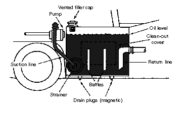
b. Shape. Figure 2-11 shows some of the design features of a reservoir. It should be high and narrow rather than shallow and broad. The oil level should be as high as possible
above the opening to a pump's suction line. This prevents the vacuum at the line opening
from causing a vortex or whirlpool effect, which would mean that a system is probably tak-
ing in air. Aerated oil will not properly transmit power because air is compressible. Aerated oil has a tendency to break down and lose its lubricating ability.
c. Size. Reservoir sizes will vary. However, a reservoir must be large enough so that it has a reserve of oil with all the cylinders in a system fully extended. An oil reserve must be high enough to prevent a vortex at the suction line's opening. A reservoir must have sufficient space to hold all the oil when the cylinders are retracted, as well as allow space for
expansion when the oil is hot.
A common-size reservoir on a mobile machine is a 20- or 30-gallon tank used with a 100-
GPM system. Many 10-GPM systems operate with 2- or 3-gallon tanks because these mobile
systems operate intermittently, not constantly. For stationary machinery, a rule of thumb is that a reservoir’s size should be two to three times a pump’s output per minute.
A large size tank is highly desirable for cooling. The large surface areas exposed to the
outside air transfer heat from the oil. Also, a large tank helps settle out the contaminates and separates the air by reducing recirculation.
d. Location. Most mobile equipment reservoirs are located above the pumps. This
creates a flooded-pump-inlet condition. This condition reduces the possibility of pump
Figure 2-11. Design features of a reservoir
2-10
Hydraulic Systems
FM 5-499
cavitation—a condition where all the available space is not filled and often metal parts will erode. Flooding the inlet also reduces the vortex tendency at a suction pipe's opening.
The location of a reservoir affects heat dissipation. Ideally, all tank walls should be
exposed to the outside air. Heat moves from a hot substance to a cold substance; heat trans-
fer is greatest when there is a large temperature difference. Reservoirs that are built into front-end loader arms are very effective in transferring heat.
e. Ventilation and Pressurization. Most reservoirs are vented to the atmosphere. A
vent opening allows air to leave or enter the space above the oil as the level of the oil goes up or down. This maintains a constant atmospheric pressure above the oil. A reservoir filter
cap, with a filter element, is often used as a vent.
Some reservoirs are pressurized, using a simple pressure-control valve rather than a
vented one. A pressure-control valve automatically lets filtered air into a tank but prevents air release unless the pressure reaches a preset level. A pressurized reservoir takes place
when the oil and air in a tank expand from heat.
f. Line Connections. A pump suction and a tank's return lines should be attached by
flanges or by welded heavy-duty couplings. Standard couplings usually are not suitable
because they spread when welded. If a suction line is connected at the bottom, a coupling
should extend well above the bottom, inside the tank; residual dirt will not get in a suction line when a tank or strainer is cleaned. A return line should discharge near a tank's bottom always below the oil level. A pipe is usually cut at a 45-degree angle and the flow aimed
away from a suction line to improve circulation and cooling.
A baffle plate is used to separate a suction line from a return line. This causes the
return oil to circulate around an outer wall for cooling before it gets to the pump again. A baffle plate should be about two-thirds the height of a tank. The lower corners are cut diagonally to allow circulation. They must be larger in area than a suction line's cross section.
Otherwise the oil level between a return and a suction side might be uneven. Baffling also
prevents oil from sloshing around when a machine is moving. Many large reservoirs are
cross-baffled to provide cooling and prevent sloshing.
g. Maintenance. Maintenance procedures include draining and cleaning a reservoir. A tank should have a dished bottom that is fitted with a drain plug at its lowest point; a plug fitting should be flushed with the inside of a tank to allow for full drainage. On large tanks, access plates may be bolted on the ends for easy removal and servicing. A reservoir should
have a sight gauge or dipstick for checking the oil level to prevent damage from lubrication
loss.
The strainers on a pump's suction line may not require as much maintenance. However,
an element in a filter in a return line will require regular changing. Therefore, that filter should not be inside a reservoir. When a reservoir is pressurized by compressed air, moisture can become a maintenance problem. A tank should have a water trap for moisture
removal; it should be placed where it can be inspected daily.
2-4. Strainers and Filters. To keep hydraulic components performing correctly, the
hydraulic liquid must be kept as clean as possible. Foreign matter and tiny metal particles
from normal wear of valves, pumps, and other components are going to enter a system.
Strainers, filters, and magnetic plugs are used to remove foreign particles from a hydraulic
Hydraulic Systems
2-11
FM 5-499
liquid and are effective as safeguards against contamination. Magnetic plugs, located in a
reservoir, are used to remove the iron or steel particles from a liquid.
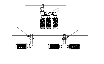
a. Strainers. A strainer is the primary filtering system that removes large particles of foreign matter from a hydraulic liquid. Even though its screening action is not as good as a filter's, a strainer offer less resistance to flow. A strainer usually consists of a metal frame wrapped with a fine-mesh wire screen or a screening element made up of varying thickness
of specially processed wire. Strainers are used to pump inlet lines (Figure 2-11, page 2-10)
where pressure drop must be kept to a minimum.
Figure 2-12 shows a strainer in three possible arrangements for use in a pump inlet
line. If one strainer causes excessive flow friction to a pump, two or more can be used in parallel. Strainers and pipe fittings must always be below the liquid level in the tank.
b. Filters. A filter removes small foreign particles from a hydraulic fluid and is most effective as a safeguard against contaminates. Filters are located in a reservoir, a pressure line, a return line, or in any other location where necessary. They are classified as full flow or proportional flow.
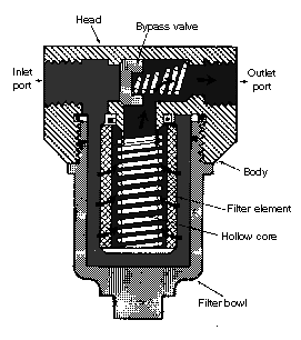
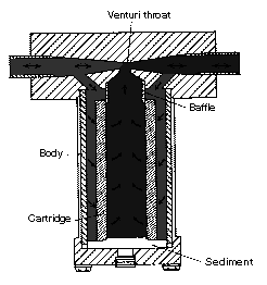
(1) Full-Flow Filter (Figure 2-13). In a full-flow filter, all the fluid entering a unit
passes through a filtering element. Although a full-flow type provides a more positive filtering action, it offers greater resistance to flow, particularly when it becomes dirty. A hydraulic liquid enters a full-flow filter through an inlet port in the body and flows around an
Pipe joints submerged
Oil level
Pump intake
connection
Disconnect union to remove
strainers for cleaning
Oil level
Access opening should be provided so strainers may be
removed for cleaning without draining tank
Figure 2-12. Hydraulic-system strainers
2-12
Hydraulic Systems
FM 5-499
element inside a bowl. Filtering
occurs as a liquid passes through
the element and into a hollow core,
leaving the dirt and impurities on
the outside of the element. A fil-
tered liquid then flows from a hol-
low core to an outlet port and into
the system.
A bypass relief valve in a body
allows a liquid to bypass the ele-
ment and pass directly through an
outlet port when the element
becomes clogged. Filters that do
not have a bypass relief valve have
a contamination indicator. This
indicator works on the principle of
the difference in pressure of a fluid
as it enters a filter and after it