Hydraulics by Department of the Army - HTML preview
Download the book in PDF, ePub, Kindle for a complete version.
Figure 3-19. In-line piston pump
against a shoe plate. This action holds the piston shoes against a swash plate, ensuring
that the pistons will reciprocate as the cylinder turns. A swash plate is stationary in a fixed-displacement design.
(c) Operation. A variable-displacement in-line pump operates the same as a fixed angle
except that a swash plate is mounted on a pivoted yoke. A yoke can be swung to change a
plate angle and thus change a pump’s displacement. A yoke can be positioned manually
with a screw or lever or by a compensator control, which positions a yoke automatically to
maintain constant output pressure under variable flow requirements. A compensator con-
trol consists of a valve that is balanced between a spring and system pressure and a spring-
loaded, yoke-actuating piston that is controlled by a valve. A pump’s compensator control
thus reduces its output only to the volume required to maintain a preset pressure. Maxi-
mum delivery is allowed only when pressure is less than a compensator’s setting.
(2) Wobble-Plate In-Line Pump. This is a variation of an in-line piston pump. In this
design, a cylinder barrel does not turn; a plate wobbles as it turns, and the wobbling pushes the pistons in and out of the pumping chambers in a stationary cylinder barrel. In a wobble-plate pump, separate inlet and outlet check valves are required for each piston, since the pistons do not move past a port.
Pumps
3-13
FM 5-499
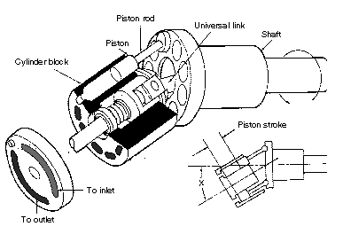
(3) Bent-Axis Axial Piston Pump. In an angle- or a bent-axis-type piston pump (Figure
3-20), the piston rods are attached by ball joints to a drive shaft’s flange. A universal link keys a cylinder block to a shaft so that they rotate together but at an offset angle. A cylinder barrel turns against a slotted valve plate to which the ports connect. Pumping action is the same as an in-line pump. The angle of offset determines a pump’s displacement, just as the
swash plate’s angle determines an in-line pump's displacement. In fixed-delivery pumps,
the angle is constant. In variable models, a yoke mounted on pintles swings a cylinder block to vary displacement. Flow direction can be reversed with appropriate controls.
3-9. Pump Operation. The following paragraphs address some of the problems that could occur when a pump is operating:
a. Overloading. One risk of overloading is the danger of excess torque on a drive shaft.
Torque is circular force on an object. An increase in pressure/pump displacement will
increase the torque on a shaft if pump displacement/pressure remains constant. Often in a
given package size, a higher GPM pump will have a lower pressure rating than a lower GPM
pump. Sometimes a field conversion to get more speed out of an actuator will cause a pump
to be overloaded. You may need a larger pump.
b. Excess Speed. Running a pump at too high a speed causes loss of lubrication, which can cause early failure. If a needed delivery requires a higher drive speed than a pump's rating, use a higher displacement pump. Excess speed also runs a risk of damage from cavita-
tion.
c. Cavitation. Cavitation occurs where available fluid does not fill an existing space. It often occurs in a pump’s inlet when conditions are not right to supply enough oil to keep an
inlet flooded. Cavitation causes the metal in an inlet to erode and the hydraulic oil to deteriorate quicker. Cavitation can occur if there is too much resistance in an inlet’s line, if a res-Figure 3-20. Bent-axis axial piston pump
3-14
Pumps
FM 5-499
ervoir’s oil level is too far below the inlet, or if an oil’s viscosity is too high. It can also occur if there is a vacuum or even a slight positive pressure at the inlet. A badly cavitating pump has oil bubbles exploding in the void. The only way to be sure a pump is not cavitating is to check the inlet with a vacuum gauge.
To prevent cavitation, keep the inlet clean and free of obstructions by using the correct
length of an inlet’s line with minimum bends. Another method is to charge an inlet. The eas-iest way to do this is to flood it by locating the reservoir above the pump’s inlet. If this is not possible and you cannot create good inlet conditions, use a pressurized reservoir. You can
also use an auxiliary pump to maintain a supply of oil to an inlet at low pressure. You could use a centrifugal pump, but it is more common to use a positive-displacement gear pump
with a pressure-relief valve that is set to maintain the desired charging pressure.
d. Operating Problems. Pressure loss, slow operation, no delivery, and noise are common operating problems in a pump.
(1) Pressure Loss. Pressure loss means that there is a high leakage path in a system. A
badly worn pump could cause pressure loss. A pump will lose its efficiency gradually. The
actuator speed slows down as a pump wears. However, pressure loss is more often caused by
leaks somewhere else in a system (relief valve, cylinders, motors).
(2) Slow Operation. This can be caused by a worn pump or by a partial oil leak in a sys-
tem. Pressure will not drop, however, if a load moves at all. Therefore, hp is still being used and is being converted into heat at a leakage point. To find this point, feel the components for unusual heat.
(3) No Delivery. If oil is not being pumped, a pump—
•
Could be assembled incorrectly.
•
Could be driven in the wrong direction.
•
Has not been primed. The reasons for no prime are usually improper start-up,
inlet restrictions, or low oil level in a reservoir.
•
Has a broken drive shaft.
(4) Noise. If you hear any unusual noise, shut down a pump immediately. Cavitation
noise is caused by a restriction in an inlet line, a dirty inlet filter, or too high a drive speed.
Air in a system also causes noise. Air will severely damage a pump because it will not have
enough lubrication. This can occur from low oil in a reservoir, a loose connection in an inlet, a leaking shaft seal, or no oil in a pump before starting. Also, noise can be caused by worn or damaged parts, which will spread harmful particles through a system, causing more damage if an operation continues.
Pumps
3-15
FM 5-499
CHAPTER 4
Hydraulic Actuators
A hydraulic actuator receives pressure energy and converts it to mechanical force and
motion. An actuator can be linear or rotary. A linear actuator gives force and motion outputs in a straight line. It is more commonly called a cylinder but is also referred to as a ram, reciprocating motor, or linear motor. A rotary actuator produces torque and rotating motion.
It is more commonly called a hydraulic motor or motor.
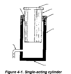
4-1. Cylinders. A cylinder is a hydraulic actuator that is constructed of a piston or plunger that operates in a cylindrical housing by the action of liquid under pressure. Figure 4-1
shows the basic parts of a cylinder. A cylinder housing is a tube in which a plunger (piston) operates. In a ram-type cylinder, a ram actuates a load directly. In a piston cylinder, a piston rod is connected to a piston to actuate a load. An end of a cylinder from which a rod or plunger protrudes is a rod end. The opposite end is a head end. The hydraulic connections
are a head-end port and a rod-end port (fluid supply).
a. Single-Acting Cylinder. This cylinder (Figure 4-1) only has a head-end port and is operated hydraulically in one direction. When oil is pumped into a port, it pushes on a
plunger, thus extending it. To return or retract a cylinder, oil must be released to a reservoir. A plunger returns either because of the weight of a load or from some mechanical force such as a spring. In mobile equipment, flow to and from a single-acting cylinder is controlled by a reversing directional valve of a single-acting type.
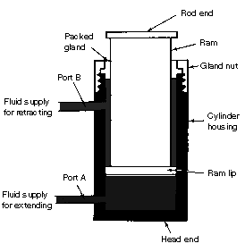
b. Double-Acting Cylinder. This cylin-
der (Figure 4-2, page 4-2) must have ports
Rod end
at the head and rod ends. Pumping oil into
Packed
Ram
the head end moves a piston to extend a
gland
rod while any oil in the rod end is pushed
Gland nut
out and returned to a reservoir. To retract
a rod, flow is reversed. Oil from a pump
goes into a rod end, and a head-end port is
Cylinder
connected to allow return flow. The flow
housing
direction to and from a double-acting cylin-
der can be controlled by a double-acting
directional valve or by actuating a control
of a reversible pump.
Fluid
supply
c. Differential Cylinder. In a differen-
tial cylinder, the areas where pressure is
applied on a piston are not equal. On a
head end, a full piston area is available for
applying pressure. At a rod end, only an
Head end
annular area is available for applying
pressure. A rod’s area is not a factor, and
Figure 4-1. Single-acting cylinder
Hydraulic Actuators
4-1
FM 5-499
what space it does take up reduces
the volume of oil it will hold. Two
general rules about a differential
cylinder are that—
•
With an equal GPM
delivery to either end, a
cylinder will move
faster when retracting
because of a reduced vol-
ume capacity.
•
With equal pressure at
either end, a cylinder
can exert more force
when extending because
of the greater piston
area. In fact, if equal
pressure is applied to
both ports at the same
time, a cylinder will
extend because of a
higher resulting force
on a head end.
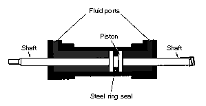
d. Nondifferential Cylinder.
This cylinder (Figure 4-3) has a pis-
Figure 4-2. Double-acting cylinder
ton rod extending from each end. It
has equal thrust and speed either
way, provided that pressure and flow
are unchanged. A nondifferential cylinder is rarely used on mobile equipment.
e. Ram-Type Cylinder. A ram-type cylinder is a cylinder in which a cross-sectional area of a piston rod is more than one-half a cross-sectional area of a piston head. In many cylinders of this type, the rod and piston heads have equal areas. A ram-type actuating cylinder
is used mainly for push
functions rather than
pull.
Figure 4-1, page 4-1,
shows a single-acting,
ram-type cylinder. A sin-
gle-acting ram applies
force in one direction.
This cylinder is often
used in a hydraulic jack.
In a double-acting, ram-
type cylinder, both
strokes of a ram are pro-
duced by pressurized
Figure 4-3. Nondifferential cylinder
fluid. Figure 4-2 shows
this cylinder.
4-2
Hydraulic Actuators
FM 5-499
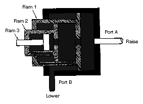
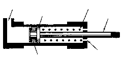
Figure 4-4 shows a telescop-
ing, ram-type, actuating cylinder,
which can be a single- or double-
acting type. In this cylinder, a
series of rams are nested in a tele-
scoping assembly. Except for the
smallest ram, each ram is hollow
and serves as a cylinder housing
for the next smaller ram. A ram
assembly is contained in a main
cylinder housing, which also pro-
vides the fluid ports. Although an
assembly requires a small space
with all of the rams retracted, a
telescoping action of an assembly
provides a relatively long stroke
when the rams are extended.
f. Piston-Type Cylinder. In
this cylinder, a cross-sectional
area of a piston head is referred to
as a piston-type cylinder. A pis-
Figure 4-4. Telescoping, ram-type, actuating
ton-type cylinder is used mainly
cylinder
when the push and pull functions
are needed.
A single-acting, piston-type cylinder uses fluid pressure to apply force in one direction.
In some designs, the force of gravity moves a piston in the opposite direction. However, most cylinders of this type apply force in both directions. Fluid pressure provides force in one
direction and spring tension provides force in the opposite direction.
Figure 4-5 shows a single-
acting, spring-loaded, piston-
type cylinder. In this cylinder, a
Fluid port
Return spring
spring is located on the rod side
of a piston. In some spring-
Piston
Piston rod
loaded cylinders, a spring is
located on a blank side, and a
fluid port is on a rod end of a cyl-
inder.
Most piston-type cylinders
Air vent
are double-acting, which means
Seals
that fluid under pressure can be
applied to either side of a piston
to provide movement and apply
force in a corresponding direc-
Figure 4-5. Single-acting, spring-loaded, piston-
tion. Figure 4-6 shows a double-
type cylinder
acting piston-type cylinder.
Hydraulic Actuators
4-3
FM 5-499
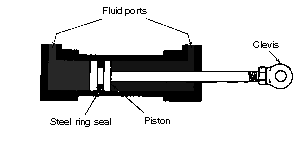
This cylinder contains one piston and piston-rod assembly and operates from fluid flow in
either direction. The two fluid ports, one near each end of a cylinder, alternate as an inlet and an outlet, depending on the directional-control valve flow direction. This is an unbalanced cylinder, which means that there is a difference in the effective working area on the
two sides of a piston. A cylinder is normally installed so that the head end of a piston carries the greater load; that is, a cylinder carries the greater load during a piston-rod extension
stroke.
Figure 4-6 shows a bal-
anced, double-acting, piston-
type cylinder. The effective
working area on both sides of
a piston is the same, and it
exerts the same force in both
directions.
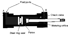
g. Cushioned Cylinder.
To slow an action and prevent
shock at the end of a piston
stroke, some actuating cylin-
Figure 4-6. Double-acting, piston-type cylinder
ders are constructed with a
cushioning device at either or both ends of a cylinder. This cushion is usually a metering
device built into a cylinder to restrict the flow at an outlet port, thereby slowing down the motion of a piston. Figure 4-7 shows a cushioned actuating cylinder.
h. Lockout Cylinders. A
lockout cylinder is used to
lock a suspension mechanism
of a tracked vehicle when a
vehicle functions as a stable
platform. A cylinder also
serves as a shock absorber
when a vehicle is moving.
Each lockout cylinder is con-
nected to a road arm by a
control lever. When each
road wheel moves up, a con-
trol lever forces the respec-
Figure 4-7. Cushioned, actuating cylinder
tive cylinder to compress.
Hydraulic fluid is forced
around a piston head through restrictor ports causing a cylinder to act as a shock absorber.
When hydraulic pressure is applied to an inlet port on each cylinder’s connecting eye, an inner control-valve piston is forced against a spring in each cylinder. This action closes the restrictor ports, blocks the main piston’s motion in each cylinder, and locks the suspension system.
4-2. Construction and Application. A cylinder is constructed of a barrel or tube, a piston and rod (or ram), two end caps, and suitable oil seals. A barrel is usually seamless steel tubing, or cast, and the interior is finished very true and smoothly. A steel piston rod is highly polished and usually hard chrome-plated to resist pitting and scoring. It is supported in the
end cap by a bushing or polished surface.
4-4
Hydraulic Actuators
FM 5-499
The cylinder's ports are built into the end caps, which can be screwed on to the tubes,
welded, or attached by tie bolts or bolted flanges. If the cylinder barrel is cast, the head-end cap may be integral with it. Mounting provisions often are made in the end caps, including
flanges for stationary mounting or clevises for swinging mounts.
Seals and wipers are installed in the rod's end cap to keep the rod clean and to prevent
external leakage around the rod. Other points where seals are used are at the end cap and
joints and between the piston and barrel. Depending on how the rod is attached to the pis-
ton, a seal may be needed. Internal leakage should not occur past a piston. It wastes energy and can stop a load by a hydrostatic lock (oil trapped behind a piston).
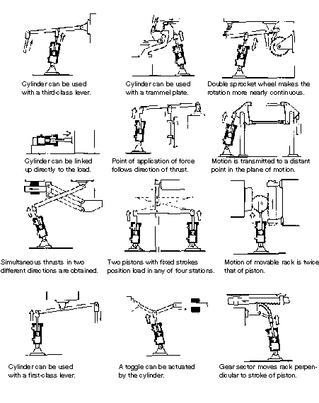
Figure 4-8, page 4-6, shows force-and-motion applications of cylinders. Because fluid
power systems have many requirements, actuating cylinders are available in different
shapes and sizes. A cylinder-type actuator is versatile and may be the most trouble-free
component of fluid-powered systems. A cylinder and a mechanical member of a unit to be
actuated must be aligned correctly. Any misalignment will cause excessive wear of a piston,
a piston rod, and the seals. Also, a piston rod and an actuating unit must stay properly
adjusted. Clean the exposed ends of the piston rods to ensure that foreign matter does not
get into the cylinders.
4-3. Maintenance. Hydraulic cylinders are compact and relatively simple. The key points to watch are the seals and pivots. The following lists service tips in maintaining cylinders: a. External Leakage. If a cylinder’s end caps are leaking, tighten them. If the leaks still do not stop, replace the gasket. If a cylinder leaks around a piston rod, replace the packing.
Make sure that a seal lip faces toward the pressure oil. If a seal continues to leak, check
paragraphs 4-3 e through i.
b. Internal Leakage. Leakage past the piston seals inside a cylinder can cause sluggish movement or settling under load. Piston leakage can be caused by worn piston seals or rings
or scored cylinder walls. The latter may be caused by dirt and grit in the oil.
NOTE: When repairing a cylinder, replace all the seals and packings
before reassembly.
c. Creeping Cylinder. If a cylinder creeps when stopped in midstroke, check for internal leakage (paragraph 4-3 b). Another cause could be a worn control valve.
d. Sluggish Operation. Air in a cylinder is the most common cause of sluggish action.
Internal leakage in a cylinder is another cause. If an action is sluggish when starting up a system, but speeds up when a system is warm, check for oil of too high a viscosity (see the
machine's operating manual). If a cylinder is still sluggish after these checks, test the whole circuit for worn components.
e. Loose Mounting. Pivot points and mounts may be loose. The bolts or pins may need to be tightened, or they may be worn out. Too much slop or float in a cylinder’s mountings
damages the piston-rod seals. Periodically check all the cylinders for loose mountings.
f. Misalignment. Piston rods must work in-line at all times. If they are side-loaded, the piston rods will be galled and the packings will be damaged, causing leaks. Eventually, the
piston rods may be bent or the welds broken.
Hydraulic Actuators
4-5
FM 5-499
Figure 4-8. Applications of cylinders
4-6
Hydraulic Actuators
FM 5-499
g. Lack of Lubrication. If a piston rod has no lubrication, a rod packing could seize, which would result in an erratic stroke, especially on single-acting cylinders.
h. Abrasives on a Piston Rod. When a piston rod extends, it can pick up dirt and other material. When it retracts, it carries the grit into a cylinder, damaging a rod seal. For this reason, rod wipers are often used at the rod end of a cylinder to clean the rod as it retracts.
Rubber boots are also used over the end of a cylinder in some cases. Piston rods rusting is
another problem. When storing cylinders, always retract the piston rods to protect them. If you cannot retract them, coat them with grease.
i. Burrs on a Piston Rod. Exposed piston rods can be damaged by impact with hard
objects. If a smooth surface of a rod is marred, a rod seal may be damaged. Clean the burrs on a rod immediately, using crocus cloth. Some rods are chrome-plated to resist wear.
Replace the seals after restoring a rod surface.
j. Air Vents. Single-acting cylinders (except ram types) must have an air vent in the dry side of a cylinder. To prevent dirt from getting in, use different filter devices. Most are self-cleaning, but inspect them periodically to ensure that they operate properly.
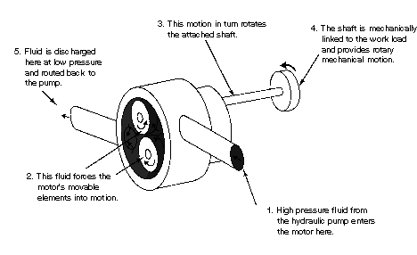
4-4. Hydraulic Motors. Hydraulic motors convert hydraulic energy into mechanical
energy. In industrial hydraulic circuits, pumps and motors are normally combined with a
proper valving and piping to form a hydraulic-powered transmission. A pump, which is
mechanically linked to a prime mover, draws fluid from a reservoir and forces it to a motor.
A motor, which is mechanically linked to the workload, is actuated by this flow so that
motion or torque, or both, are conveyed to the work. Figure 4-9 shows the basic operations of a hydraulic motor.
Figure 4-9. Basic operations of a hydraulic motor
Hydraulic Actuators
4-7
FM 5-499
The principal ratings of a motor are torque, pressure, and displacement. Torque and
pressure ratings indicate how much load a motor can handle. Displacement indicates how
much flow is required for a specified drive speed and is expressed in cubic inches per revolutions, the same as pump displacement. Displacement is the amount of oil that must be
pumped into a motor to turn it one revolution. Most motors are fixed-displacement; how-
ever, variable-displacement pis-
ton motors are in use, mainly in
hydrostatic drives. The main
types of motors are gear, vane,
and piston. They can be unidi-
rectional or reversible. (Most
motors designed for mobile
equipment are reversible.)
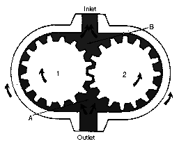
a. Gear-Type Motors. Fig-
ure 4-10 shows a gear-type
motor. Both gears are driven
gears, but only one is connected
to the output shaft. Operation is
essentially the reverse of that of
a gear pump. Flow from the
pump enters chamber A and
flows in either direction around
the inside surface of the casing,
Figure 4-10. Gear-type motor
forcing the gears to rotate as