Microsensors by Igor V. Minin and Oleg V. Minin - HTML preview
Download the book in PDF, ePub, Kindle for a complete version.
2
1
1
m V s
Hn
0.15
MGT
2: Ga Sb, with
2
1
1
m V s
Hn
0.50
MGT
3: Ga As, with
2
1
1
m V s
Hn
0.80
The noise-equivalent magnetic induction spectral density lowers with the increase of
carriers mobility, this increase being significant for collector currents of relatively low
values. So for the collector current I
mA , the offset equivalent magnetic induction
C
0.1
value of the GaSb device decreases by 91.5% as compared to that of the silicon device
Fig. 3.12. The SNB (f) depending on the I for three devices of different materials
C
Magnetic Microsensors
43
3.8 A system to maintain the horizontal position of certain naval equipment
The present paper proposes an original solution to increase the efficiency of cardanic
suspension which ensures the stabilization of horizontal position for gyrocompass and radar
antenna.
A. Two platforms that can spin simultaneously, but independent of each other, driven by
two direct current reversible motors are used.
B. The signals that determine the value of the engine supply voltage are given by two
position transducers made up of with lateral bipolar magnetotransistors in differential
connection.
On merchant ships, the establishment of both the horizontal position of the gyroscopic
compass and the radar antenna is accomplished with the help of the suspension on 3
gimbals circles which eliminates the unwanted effect of rolling and pitching for the values
included in the range -10° ÷ 10°.
An original solution wherewith the system of the gimbals suspension becomes capable for
the pitching angles of the ship that oversteps the mentioned limits is the use of 2
superimposed platforms which are simultaneously rotating, but independently.
The driving shaft which constitutes at the same time the sustaining element of the first
platform is horizontally disposed and parallel with the longitudinal axis of the ship. It is
supported by bearings whose bolsters are mounted on a fixed element in the ship's
structure. By rotating it this platform decreases the effect of the rolling.
The second platform which holds the suspension gimbals system is also sustained by her
own shaft whose bearings have the holders jammed tight on the first platform. Being on the
longitudinal axis of the ship, the leading shaft of this platform enables a rotating motion
which decreases the effect of the pitch. Each platform is operated by a reversible direct
current motor.
The signals which determine the bridge driving voltage polarity for the 2 engines are given
by the position transducers made with magnetic transistors in differential connection.
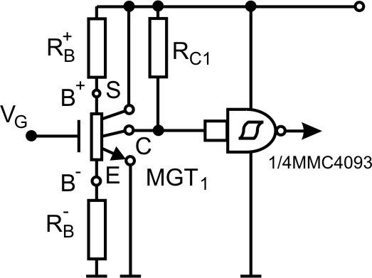
3.9 The presentation of the Hall transducer
The magnetotransistor used in the construction of the displacement transducer (figure 3.13)
has the structure of a MOS transistor with long channel but operates as a lateral bipolar
transistor with a drift-aided field in the base region.
In the presence of a magnetic field adequately oriented the collector current is very small. If
the magnetic induction decreases the device current increase which brings about the
collector potential variation V :
C
L
V
R I
R
I B
(3.15)
C
C 1
C
C 1
Hn C
Y
The outlet of the magnetic transistor is connected to the inlet of a logical gate of ,,trigger
Schmitt” type (ex.CDB413 or MMC4093) so that it supplies logic level ,,0" signal, when the
magnetic induction increases and logic level ,,1" when the magnetic induction decreases.
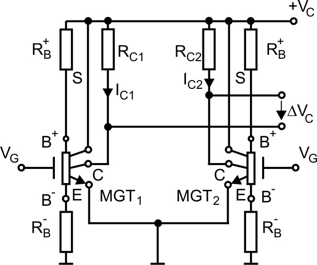
The description of the position transducer
Because by rotating one of the platforms eliminates the effect of rolling, and the other one
the effect of pitching we use a transducer for every platform. The two sensors of the
transducer (figure 3.14) are magnetic transistors with MOS structure that function as lateral
44
Microsensors
bipolar transistors with supplementary drift field in the base region. For this kind of
polarized device, the theoretical analysis shows that in case of a constant polarization, for a
certain material and a geometry given to the device I B . The two magnetic transistors C
are within the field of an magnetic pendulum. In the absence of the rolling or pitching, the
pendulum is in a median position and the magnetic fields for the two magnetic transistors
are equal. Therefore, I I and at the outlet of the transducer the voltage is V
.
C
0
C 1
C 2
At the inclination of the ship because of the rolling, to the port (or starboard) the induction
value for a sensor is increasing, for exempt. MGT1, and decreasing for the other one. The
balance of the two collector currents disappears even if I I the voltage at the outlet of C 1
C 2
the transducer is:
V
R I I
(3.16)
C
C ( C
C )
0
1
2
If the ship is listed in the other way, then I I and it results:
C 1
C 2
V
R I I
(3.17)
C
C ( C
C )
0
1
2
For the platform that can spin around an axis parallel to the longitudinal axis, the transducer
pendulum moves in a plane perpendicular on the longitudinal axis of the ship, and for the
other platform the magnetic pendulum of the transducer can move in a vertical plane in
parallel with the longitudinal axis of the ship.
Fig. 3.13. The electric diagram of Hall transducer
Magnetic Microsensors
45
Fig. 3.14. The position transducer with magnetotransistor
Block diagram and the role of the component circuits
The block diagram (figure 3.15) contains: transducer T, integrator I, amplifier A, comparator
C and the control assembly and energy supply of the motor BCA.
The level of signal to the outlet of the transducer is proportional to the ship's inclination
angle, and its polarity shows the orientation of the ship's inclination.
The integrator eliminates the high frequency oscillations of the pendulum (the chip's
oscillation frequency is reduced by fractions of Hz.
At the same time the integrator produces a small delay in the operating voltage variation of
the engine, useful for the platform to reestablish the initial horizontal position. An essential
contribution to this is the mechanic inertia of the system.
After amplification, the signal emitted by the transducer is compared with an additional
reference transmission.
The comparator's threshold can be adjusted according to the delay produced by the
integrator and the actuator mechanism inertia.
Fig. 3.15. The block diagram of the installation
46
Microsensors
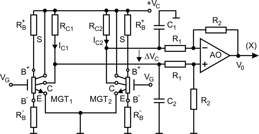
The principle diagram and operating conditions
In figure 3.16 is presented the principle diagram of the transducer and amplifier. If the
inclination of the ship to starboard brings the unbalance of the collector currents I I
C 1
C 2
the transducer produces the signal:
V
R I I
V V
(3.18)
C
C ( C
C )
0
1
2
2
1
The operational is in a differential amplifier configuration and the outlet voltage is:
V (
R / R ) V
(3.19)
C
0
0
2
1
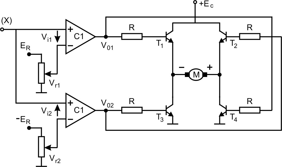
In figure 3.17 is presented the principle diagram of the motors’ supply and control block.
When V 0 the voltage at the inputs of the two comparators have separate polarity. When
0
V 0 , V V V ,and the output of the comparator C, is in DOWN state, therefore: i
rl
0
0
1
0
V V which insures the blockage of the transistors T
L
0
01
0
1 and T3.
In the same state , V 0 at the input of the comparator C
V V V , it
i
r
0
0
2 the voltage, is
2
2
0
passes in the UP state, V V , which determines the conduction of the transistors T
H
0
02
0
2
and T4, the polarity voltage at the jacks of the motor is the one indicated in the figure 3.17.
The direction of rotation is thereby given so that by moving the platform for the rolling
compensation the balance of the two collector currents is re-established.
Clearly at the inclination of the ship to the port the outlet of the comparator C1, passes in the
UP state, conducts the transistors T1 , T3 the direction of the bridge driving voltage changes and the motor will rotate in the opposite direction re-establishing the horizontal position of
the platform.
Fig. 3.16. The transducer and the differential amplifier
Magnetic Microsensors
47
Fig. 3.17. The control and supply diagram of the motor
4. Conclusions
The presented system together with the cardanic suspension system eliminate the oscillation
exceed of the ship in case of amplitudes that exceed 10 o
. The use of magnetotransistors as
magnetic sensors allows for the achieving of same current-voltage conversion circuits, more
efficient than the conventional circuits with Hall plates. Although the magnetotransistors
have a low magnetic sensitivity, very large signal-to-noise ratios are obtained, hence, a high
magnetic induction resolution is resulting. The possibility of having the sensor and the
amplifier circuit on the same chip has lead to the achievement of transducers with high
conversion efficiency as well as to increase in their range of practical work.
5. References
[1] Bodea M., “Traductoare integrate”, Microelectronica, vol. 15, pp. 73-86, Editura
Academiei R.S.Romania, Bucureşti, 1987
[2] Căruntu G., “Măsurări galvanomagnetice în dispozitive semiconductoare”, Buletinul
Sesiunii de Comunicări Ştiinţifice SECOMAR ’99, Academia Navală ”Mircea Cel
Bătrân”, Constanţa, vol. II, pp. 69-74, 1999
[3] Gray R.P., Meyer G.R., “Circuite integrate analogice. Analiză şi proiectare”, Editura
Tehnică, Bucureşti, 1973
[4] F.N. Hooge “1/f noise is no surface effect”, Phys., 1969 Lett. 29A 139-40
[5] Middelhoek S., Audet S.A., “Physiscs of Silicon Sensors”, Academic Press, London,
1989
48
Microsensors
[6] P.S. Kireev, “Fizica semiconductorilor”, Editura Ştiinţifică şi Enciclopedică, Bucureşti
1977
[7] A. Nathan, H.P. Baltes, “Two dimensional numerical modelling of magnetic field
sensors in CMOC technology”, IEEE Trans Electron Devices ED-32 1212-19, 1985.
[8] R.S. Popovic , "Hall Effect Devices, Magnetic Sensors and Characterization of
Semiconductors", Adam Hilger, Bristol , England , 1991
2
Photoelectronic Magnetic Microsensor
with a Digit Readout
Hsing-Cheng Chang
Feng Chia University, Taichung, 40724
Taiwan
1. Introduction
The magnetic microsensor is a small detective device for sensing magnetic effects and
transferring to measurable signals. Magnetic microsensors are important in various
application areas that are biomagnetism, geomagnetism, nondestructive testing, automobile,
field measurement, identification and communication. Eleven technologies have been
described for magnetic field measurements that are search-coil, flux-gate, optically pumped,
nuclear precession, SQUID, Hall-effect, magnetoresistive, magnetodiode, magnetotransistor,
fiber optical, and magneto-optic (Lenz, 1990). Four-type classification of magnetic
microsensors by principle are also summarised that are galvanic, conductimetric, voltaic,
and acoustics (Gardner et al., 2001). The trend of sensor development is toward lower cost,
small dimension, lower power consumption, and higher performance. A new physics
phenomenon using new fabrication technology and improved materials for new
applications should be the development trends in magnetic microsensors. Recent progress
in applications of FBG sensors has reported (Lee, 2003, Rao, 1999). Different researches on
optical magnetic sensors have been addressed by fiber-optic interferometric (Oh et al., 1997,
Wang et al., 2008), cantilever bending (Keplinger et al., 2003), Lorentzian force (Okamura,
1990), or magnetic materials (Meng et al., 2001).
Operational principles based on electromagnetic systems, magnetic material properties,
stress-induced magnetic interrelationship, fiber gratings, and superconductivity have been
widely studied for magnetic detection or measurement (Ciudad et al., 2004; Dimitropoulos
et al., 2003; Mapps, 1997; Sedlar et al., 2000; Seo et al., 2001). It must be noticed in magnetic
sensors development to immunity the factors of temperature and humidity and optical fiber
sensors can be designed to fit the requirement. To develop magnetic microsensor using
optical fiber sensing method becomes popular due to the advantages of electromagnetic
immunity, electronic isolation, low cost, light weight, small size, and anti-corrosive. Fiber
grating sensors has been reviewed based on different grating sensing methods, including
Bragg gratings, chirped gratings, long period-based gratings, and intragrating concepts
(Kersey et al, 1997). The permalloy-on-membrane type of magnetic actuators with flexural
cantilevers and torsion beams are built based on microelectromechanical system (MEMS)
technology to satisfy large force and displacement requirements (Khoo & Liu, 2001, Liu &
Yi, 1990). To develop fiber Bragg grating (FBG) sensors unaffected by temperature
perturbations is important for practical applications. A precision optical fiber-based
magnetic sensor requires temperature compensation design because of deformation of
50
Microsensors
inherent temperature dependence in fiber material. Several temperature compensation
techniques in pressure or strain measurements have been established such as bimetal
cantilevers, non-uniform or dual head FBGs, double shell cylinders and biomaterial effect
(Hsu et al., 2006; Iadicicco et al., 2006; Khoo & Liu, 2001; Liu & Yi, 1990; Tian et al., 2005).
These techniques guarantee stable measurements independent of temperature perturbation
without any additional temperature-isolation or referencing process.
To develop a magnetic microsensor as a microsystem should contain environment sensing
mechanism, data processing and storage modules, and automatic calibration and
compensation functions. Because of very small magnetostriction rate below the order of 10-5,
the sensing range and reliability of magnetic field strength are limited by coating soft
magnetic film on optical fibers directly. Accordingly, microelectromechanical system
compatible FBG magnetic sensor can be designed to supply a wide measurement range with
solid reliability. A photoelectronic magnetic microsensor with a temperature compensation
function and a digital readout has been developed and fabricated as a smart sensing system.
The batch of microfabrication technology used to deposit Ni/Cr permalloy flaps that can be
driven to push the sensing FBGs by excitation magnetic force to supply capacitive and
optical outputs. The finite element method (FEM) for equivalent model simulation was
utilized to understand the coupling effect of magnetic and mechanical behaviors. The
neodymium-iron-boron (Nd-Fe-B) magnets with residual surface magnetic flux density up
to 1.26 Tesla (T) were used as excited power to investigate the influence of external magnetic
fields on the density variation of the transmitting light signal. Measurement system and
display in real-time mode were setup by connecting the designed microsensors with signal
processing circuits and a PC display module.
2. Operation principle
2.1 Sensing theory
The operational principle of the FBG-based sensors is to monitor the central wavelength
shift between input signal and back-reflected signal from the Bragg gratings. The first-order
Bragg condition is given by the expression (Morey et al., 1989)
2 n
B
eff
(1)
where neff is the effective index of the core and Λ is the period of gratings. Bragg wavelength,
λB, is the center wavelength of the back-reflected signal from the Bragg gratings.
Most of FBG sensing works have focused on the device design and fabrication for providing
quasi-distributed sensing of temperature and strain which can be described as the following
equation (Liu et al, 2007, Xu et al., 1993).
(1 P )
(
) T
e
f
f
K K T
(2)
T
B
where is the change of strain; Pe is the effective photoelastic coefficient of the fiber glass;
f is the thermal expansion coefficient of fiber; f is the thermal optic coefficient of the fiber; Δ T is the change of temperature; K is the strain sensitivity; KT is the temperature sensitivity.
The strain response arises due to both the sensor elongation induced grating pitch variation
and the photoelastic effect induced fiber index change. For measuring magnetic field
strength accurately, magnetic force induced strain should be measured effectively with
Photoelectronic Magnetic Microsensor with a Digit Readout
51
processing of temperature compensation. The relative Bragg wavelength shifts in response
to axial strain change (/B) in a packaged FBG sensor can be described as the following
equation (Liu et al., 2000).
P
(1 P ) K P
(3)
e
P
B
E
where Pe is the effective photoelastic coefficient; Kp is the pressure sensitivity; E is the Young’s modulus of the fiber; P is the change of pressure.
When applying strain and temperature in the fiber, the effective index of the core and the
uniform distribution of gratings will be affected to induce the shift in Bragg wavelength. It
simply can be expressed using
B C
C T
(4)
1
2
B
where C1 and C2 present sensing parameters found to be 0.7810-12 and 6.6710-6
respectively (Kersey et al., 1997). The factors are complicated from strain-optic effect that
affected by the parameters of Poisson ratio, core effective index, Pockel’s coefficient
components, grating length variation, and total fiber grating length. It becomes
comprehensible that the variation in wavelength is the sum of the strain and temperature
terms. The sensitivities of normalized central wavelength shift to strain and temperature