College Physics (2012) by Manjula Sharma, Paul Peter Urone, et al - HTML preview
Download the book in PDF, ePub, Kindle for a complete version.
and is in a uniform 0.800-T magnetic field.
44. Calculate the magnetic field strength needed on a 200-turn square
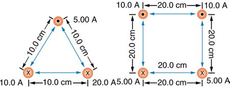
Figure 22.57
loop 20.0 cm on a side to create a maximum torque of 300 N ⋅ m if the
56. Find the direction and magnitude of the force that each wire
loop is carrying 25.0 A.
experiences in Figure 22.58(a) by, using vector addition.
45. Since the equation for torque on a current-carrying loop is
τ = NIAB sin θ , the units of N ⋅ m must equal units of A ⋅ m2 T .
Verify this.
46. (a) At what angle θ is the torque on a current loop 90.0% of
maximum? (b) 50.0% of maximum? (c) 10.0% of maximum?
CHAPTER 22 | MAGNETISM 809
64. How strong is the magnetic field inside a solenoid with 10,000 turns
per meter that carries 20.0 A?
65. What current is needed in the solenoid described in Exercise 22.58
to produce a magnetic field 104 times the Earth’s magnetic field of
5.00×10⁻⁵ T ?
66. How far from the starter cable of a car, carrying 150 A, must you be to
experience a field less than the Earth’s (5.00×10⁻⁵ T)? Assume a
Figure 22.58
57. Find the direction and magnitude of the force that each wire
long straight wire carries the current. (In practice, the body of your car
experiences in Figure 22.58(b), using vector addition.
shields the dashboard compass.)
67. Measurements affect the system being measured, such as the
22.11 More Applications of Magnetism
current loop in Figure 22.56. (a) Estimate the field the loop creates by
calculating the field at the center of a circular loop 20.0 cm in diameter
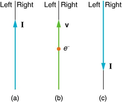
58. Indicate whether the magnetic field created in each of the three
carrying 5.00 A. (b) What is the smallest field strength this loop can be
situations shown in Figure 22.59 is into or out of the page on the left and
used to measure, if its field must alter the measured field by less than
right of the current.
0.0100%?
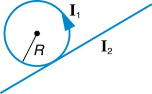
68. Figure 22.62 shows a long straight wire just touching a loop carrying
a current I 1 . Both lie in the same plane. (a) What direction must the
current I 2 in the straight wire have to create a field at the center of the
loop in the direction opposite to that created by the loop? (b) What is the
ratio of I 1 / I 2 that gives zero field strength at the center of the loop? (c)
What is the direction of the field directly above the loop under this
circumstance?
Figure 22.59
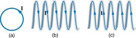
59. What are the directions of the fields in the center of the loop and coils
shown in Figure 22.60?
Figure 22.62
69. Find the magnitude and direction of the magnetic field at the point
equidistant from the wires in Figure 22.58(a), using the rules of vector
addition to sum the contributions from each wire.
70. Find the magnitude and direction of the magnetic field at the point
equidistant from the wires in Figure 22.58(b), using the rules of vector
Figure 22.60
addition to sum the contributions from each wire.
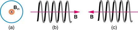
60. What are the directions of the currents in the loop and coils shown in
71. What current is needed in the top wire in Figure 22.58(a) to produce
a field of zero at the point equidistant from the wires, if the currents in the
bottom two wires are both 10.0 A into the page?
72. Calculate the size of the magnetic field 20 m below a high voltage
power line. The line carries 450 MW at a voltage of 300,000 V.
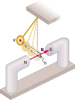
73. Integrated Concepts
(a) A pendulum is set up so that its bob (a thin copper disk) swings
Figure 22.61
between the poles of a permanent magnet as shown in Figure 22.63.
61. To see why an MRI utilizes iron to increase the magnetic field created
What is the magnitude and direction of the magnetic force on the bob at
by a coil, calculate the current needed in a 400-loop-per-meter circular
the lowest point in its path, if it has a positive 0.250 μC charge and is
coil 0.660 m in radius to create a 1.20-T field (typical of an MRI
instrument) at its center with no iron present. The magnetic field of a
released from a height of 30.0 cm above its lowest point? The magnetic
proton is approximately like that of a circular current loop
field strength is 1.50 T. (b) What is the acceleration of the bob at the
0.650×10⁻¹⁵ m
bottom of its swing if its mass is 30.0 grams and it is hung from a flexible
in radius carrying 1.05×10⁴ A . What is the field at
string? Be certain to include a free-body diagram as part of your analysis.
the center of such a loop?
62. Inside a motor, 30.0 A passes through a 250-turn circular loop that is
10.0 cm in radius. What is the magnetic field strength created at its
center?
63. Nonnuclear submarines use batteries for power when submerged. (a)
Find the magnetic field 50.0 cm from a straight wire carrying 1200 A from
the batteries to the drive mechanism of a submarine. (b) What is the field
if the wires to and from the drive mechanism are side by side? (c)
Discuss the effects this could have for a compass on the submarine that
is not shielded.
810 CHAPTER 22 | MAGNETISM
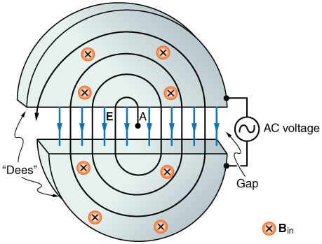
Figure 22.64 Cyclotrons accelerate charged particles orbiting in a magnetic field by
placing an AC voltage on the metal Dees, between which the particles move, so that
energy is added twice each orbit. The frequency is constant, since it is independent of
the particle energy—the radius of the orbit simply increases with energy until the
Figure 22.63
particles approach the edge and are extracted for various experiments and
74. Integrated Concepts
applications.
(a) What voltage will accelerate electrons to a speed of
81. Integrated Concepts
6.00×10⁻⁷ m/s ? (b) Find the radius of curvature of the path of a
A cyclotron accelerates charged particles as shown in Figure 22.64.
proton accelerated through this potential in a 0.500-T field and compare
Using the results of the previous problem, calculate the frequency of the
this with the radius of curvature of an electron accelerated through the
accelerating voltage needed for a proton in a 1.20-T field.
same potential.
82. Integrated Concepts
75. Integrated Concepts
(a) A 0.140-kg baseball, pitched at 40.0 m/s horizontally and
Find the radius of curvature of the path of a 25.0-MeV proton moving
perpendicular to the Earth’s horizontal 5.00×10⁻⁵ T field, has a
perpendicularly to the 1.20-T field of a cyclotron.
100-nC charge on it. What distance is it deflected from its path by the
76. Integrated Concepts
magnetic force, after traveling 30.0 m horizontally? (b) Would you
To construct a nonmechanical water meter, a 0.500-T magnetic field is
suggest this as a secret technique for a pitcher to throw curve balls?
placed across the supply water pipe to a home and the Hall voltage is
83. Integrated Concepts
recorded. (a) Find the flow rate in liters per second through a 3.00-cm-
(a) What is the direction of the force on a wire carrying a current due east
diameter pipe if the Hall voltage is 60.0 mV. (b) What would the Hall
in a location where the Earth’s field is due north? Both are parallel to the
voltage be for the same flow rate through a 10.0-cm-diameter pipe with
ground. (b) Calculate the force per meter if the wire carries 20.0 A and
the same field applied?
the field strength is 3.00×10⁻⁵ T . (c) What diameter copper wire would
77. Integrated Concepts
have its weight supported by this force? (d) Calculate the resistance per
(a) Using the values given for an MHD drive in Exercise 22.59, and
meter and the voltage per meter needed.
assuming the force is uniformly applied to the fluid, calculate the pressure 84. Integrated Concepts
created in N/m2 . (b) Is this a significant fraction of an atmosphere?
One long straight wire is to be held directly above another by repulsion
78. Integrated Concepts
between their currents. The lower wire carries 100 A and the wire 7.50
(a) Calculate the maximum torque on a 50-turn, 1.50 cm radius circular
cm above it is 10-gauge (2.588 mm diameter) copper wire. (a) What
current must flow in the upper wire, neglecting the Earth’s field? (b) What
current loop carrying 50 μA in a 0.500-T field. (b) If this coil is to be
is the smallest current if the Earth’s 3.00×10⁻⁵ T field is parallel to the
used in a galvanometer that reads 50 μA full scale, what force constant ground and is not neglected? (c) Is the supported wire in a stable or
spring must be used, if it is attached 1.00 cm from the axis of rotation and unstable equilibrium if displaced vertically? If displaced horizontally?
is stretched by the 60º arc moved?
85. Unreasonable Results
79. Integrated Concepts
(a) Find the charge on a baseball, thrown at 35.0 m/s perpendicular to
A current balance used to define the ampere is designed so that the
the Earth’s 5.00×10⁻⁵ T field, that experiences a 1.00-N magnetic
current through it is constant, as is the distance between wires. Even so,
force. (b) What is unreasonable about this result? (c) Which assumption
if the wires change length with temperature, the force between them will
or premise is responsible?
change. What percent change in force per degree will occur if the wires
are copper?
86. Unreasonable Results
80. Integrated Concepts
A charged particle having mass 6.64×10⁻²⁷ kg (that of a helium atom)
(a) Show that the period of the circular orbit of a charged particle moving
perpendicularly to a uniform magnetic field is T = 2 πm / ( qB) . (b) What moving at 8.70×10⁵ m/s perpendicular to a 1.50-T magnetic field
travels in a circular path of radius 16.0 mm. (a) What is the charge of the
is the frequency f ? (c) What is the angular velocity ω ? Note that these
particle? (b) What is unreasonable about this result? (c) Which
results are independent of the velocity and radius of the orbit and, hence,
assumptions are responsible?
of the energy of the particle. (Figure 22.64.)
87. Unreasonable Results
An inventor wants to generate 120-V power by moving a 1.00-m-long
wire perpendicular to the Earth’s 5.00×10⁻⁵ T field. (a) Find the speed
CHAPTER 22 | MAGNETISM 811
with which the wire must move. (b) What is unreasonable about this
result? (c) Which assumption is responsible?
88. Unreasonable Results
Frustrated by the small Hall voltage obtained in blood flow
measurements, a medical physicist decides to increase the applied
magnetic field strength to get a 0.500-V output for blood moving at 30.0
cm/s in a 1.50-cm-diameter vessel. (a) What magnetic field strength is
needed? (b) What is unreasonable about this result? (c) Which premise
is responsible?
89. Unreasonable Results
A surveyor 100 m from a long straight 200-kV DC power line suspects
that its magnetic field may equal that of the Earth and affect compass
readings. (a) Calculate the current in the wire needed to create a
5.00×10⁻⁵ T field at this distance. (b) What is unreasonable about this
result? (c) Which assumption or premise is responsible?
90. Construct Your Own Problem
Consider a mass separator that applies a magnetic field perpendicular to
the velocity of ions and separates the ions based on the radius of
curvature of their paths in the field. Construct a problem in which you
calculate the magnetic field strength needed to separate two ions that
differ in mass, but not charge, and have the same initial velocity. Among
the things to consider are the types of ions, the velocities they can be
given before entering the magnetic field, and a reasonable value for the
radius of curvature of the paths they follow. In addition, calculate the
separation distance between the ions at the point where they are
detected.
91. Construct Your Own Problem
Consider using the torque on a current-carrying coil in a magnetic field to
detect relatively small magnetic fields (less than the field of the Earth, for
example). Construct a problem in which you calculate the maximum
torque on a current-carrying loop in a magnetic field. Among the things to
be considered are the size of the coil, the number of loops it has, the
current you pass through the coil, and the size of the field you wish to
detect. Discuss whether the torque produced is large enough to be
effectively measured. Your instructor may also wish for you to consider
the effects, if any, of the field produced by the coil on the surroundings
that could affect detection of the small field.
812 CHAPTER 22 | MAGNETISM
CHAPTER 23 | ELECTROMAGNETIC INDUCTION, AC CIRCUITS, AND ELECTRICAL TECHNOLOGIES 813
23
ELECTROMAGNETIC INDUCTION, AC CIRCUITS,
AND ELECTRICAL TECHNOLOGIES
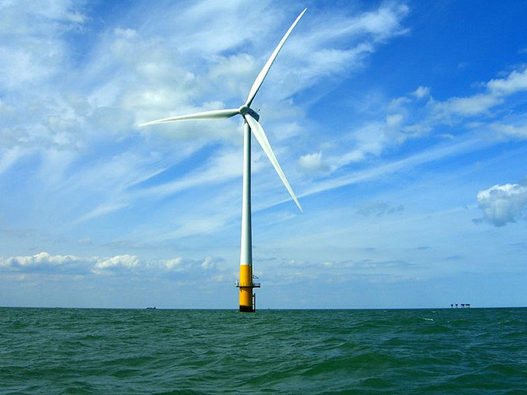
Figure 23.1 This wind turbine in the Thames Estuary in the UK is an example of induction at work. Wind pushes the blades of the turbine, spinning a shaft attached to
magnets. The magnets spin around a conductive coil, inducing an electric current in the coil, and eventually feeding the electrical grid. (credit: phault, Flickr)

814 CHAPTER 23 | ELECTROMAGNETIC INDUCTION, AC CIRCUITS, AND ELECTRICAL TECHNOLOGIES
Learning Objectives
23.1. Induced Emf and Magnetic Flux
• Calculate the flux of a uniform magnetic field through a loop of arbitrary orientation.
• Describe methods to produce an electromotive force (emf) with a magnetic field or magnet and a loop of wire.
23.2. Faraday’s Law of Induction: Lenz’s Law
• Calculate emf, current, and magnetic fields using Faraday’s Law.
• Explain the physical results of Lenz’s Law
• Calculate emf, force, magnetic field, and work due to the motion of an object in a magnetic field.
23.4. Eddy Currents and Magnetic Damping
• Explain the magnitude and direction of an induced eddy current, and the effect this will have on the object it is induced in.
• Describe several applications of magnetic damping.
• Calculate the emf induced in a generator.
• Calculate the peak emf which can be induced in a particular generator system.
• Explain what back emf is and how it is induced.
• Explain how a transformer works.
• Calculate voltage, current, and/or number of turns given the other quantities.
23.8. Electrical Safety: Systems and Devices
• Explain how various modern safety features in electric circuits work, with an emphasis on how induction is employed.
• Calculate the inductance of an inductor.
• Calculate the energy stored in an inductor.
• Calculate the emf generated in an inductor.
• Calculate the current in an RL circuit after a specified number of characteristic time steps.
• Calculate the characteristic time of an RL circuit.
• Sketch the current in an RL circuit over time.
23.11. Reactance, Inductive and Capacitive
• Sketch voltage and current versus time in simple inductive, capacitive, and resistive circuits.
• Calculate inductive and capacitive reactance.
• Calculate current and/or voltage in simple inductive, capacitive, and resistive circuits.
• Calculate the impedance, phase angle, resonant frequency, power, power factor, voltage, and/or current in a RLC series circuit.
• Draw the circuit diagram for an RLC series circuit.
• Explain the significance of the resonant frequency.
Introduction to Electromagnetic Induction, AC Circuits and Electrical Technologies
Nature’s displays of symmetry are beautiful and alluring. A butterfly’s wings exhibit an appealing symmetry in a complex system. (See Figure 23.2.)
The laws of physics display symmetries at the most basic level—these symmetries are a source of wonder and imply deeper meaning. Since we
place a high value on symmetry, we look for it when we explore nature. The remarkable thing is that we find it.
Figure 23.2 Physics, like this butterfly, has inherent symmetries. (credit: Thomas Bresson)
The hint of symmetry between electricity and magnetism found in the preceding chapter will be elaborated upon in this chapter. Specifically, we know
that a current creates a magnetic field. If nature is symmetric here, then perhaps a magnetic field can create a current. The Hall effect is a voltage
caused by a magnetic force. That voltage could drive a current. Historically, it was very shortly after Oersted discovered currents cause magnetic
fields that other scientists asked the following question: Can magnetic fields cause currents? The answer was soon found by experiment to be yes. In
1831, some 12 years after Oersted’s discovery, the English scientist Michael Faraday (1791–1862) and the American scientist Joseph Henry
(1797–1878) independently demonstrated that magnetic fields can produce currents. The basic process of generating emfs (electromotive force) and,
hence, currents with magnetic fields is known as induction; this process is also called magnetic induction to distinguish it from charging by induction,
which utilizes the Coulomb force.
Today, currents induced by magnetic fields are essential to our technological society. The ubiquitous generator—found in automobiles, on bicycles, in
nuclear power plants, and so on—uses magnetism to generate current. Other devices that use magnetism to induce currents include pickup coils in
electric guitars, transformers of every size, certain microphones, airport security gates, and damping mechanisms on sensitive chemical balances.
Not so familiar perhaps, but important nevertheless, is that the behavior of AC circuits depends strongly on the effect of magnetic fields on currents.
CHAPTER 23 | ELECTROMAGNETIC INDUCTION, AC CIRCUITS, AND ELECTRICAL TECHNOLOGIES 815
23.1 Induced Emf and Magnetic Flux
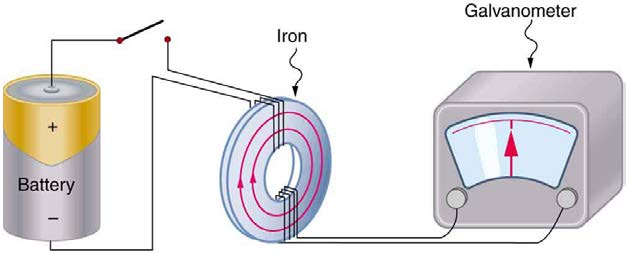
The apparatus used by Faraday to demonstrate that magnetic fields can create currents is illustrated in Figure 23.3. When the switch is closed, a
magnetic field is produced in the coil on the top part of the iron ring and transmitted to the coil on the bottom part of the ring. The galvanometer is
used to detect any current induced in the coil on the bottom. It was found that each time the switch is closed, the galvanometer detects a current in
one direction in the coil on the bottom. (You can also observe this in a physics lab.) Each time the switch is opened, the galvanometer detects a
current in the opposite direction. Interestingly, if the switch remains closed or open for any length of time, there is no current through the
galvanometer. Closing and opening the switch induces the current. It is the change in magnetic field that creates the current. More basic than the
current that flows is the emfthat causes it. The current is a result of an emf induced by a changing magnetic field, whether or not there is a path for
current to flow.
Figure 23.3 Faraday’s apparatus for demonstrating that a magnetic field can produce a current. A change in the field produced by the top coil induces an emf and, hence, a
current in the bottom coil. When the switch is opened and closed, the galvanometer registers currents in opposite directions. No current flows through the galvanometer when
the switch remains closed or open.
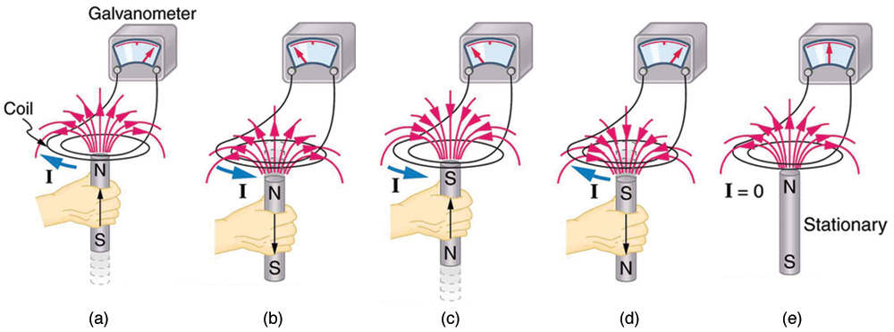
An experiment easily performed and often done in physics labs is illustrated in Figure 23.4. An emf is induced in the coil when a bar magnet is
pushed in and out of it. Emfs of opposite signs are produced by motion in opposite directions, and the emfs are also reversed by reversing poles. The
same results are produced if the coil is moved rather than the magnet—it is the relative motion that is important. The faster the motion, the greater
the emf, and there is no emf when the magnet is stationary relative to the coil.
Figure 23.4 Movement of a magnet relative to a coil produces emfs as shown. The same emfs are produced if the coil is moved relative to the magnet. The greater the speed,
the greater the magnitude of the emf, and the emf is zero when there is no motion.
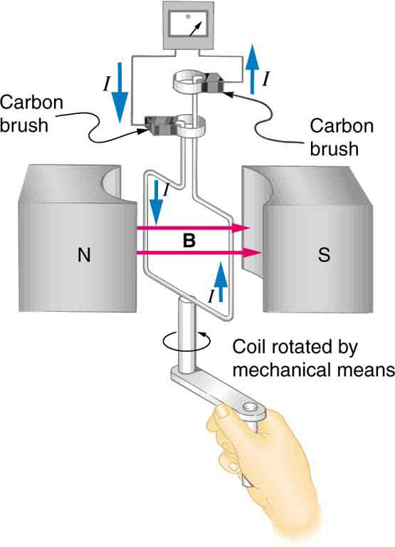
The method of inducing an emf used in most electric generators is shown in Figure 23.5. A coil is rotated in a magnetic field, producing an alternating current emf, which depends on rotation rate and other factors that will be explored in later sections. Note that the generator is remarkably similar in
construction to a motor (another symmetry).
816 CHAPTER 23 | ELECTROMAGNETIC INDUCTION, AC CIRCUITS, AND ELECTRICAL TECHNOLOGIES
Figure 23.5 Rotation of a coil in a magnetic field produces an emf. This is the basic construction of a generator, where work done to turn the coil is converted to electric energy.
Note the generator is very similar in construction to a motor.
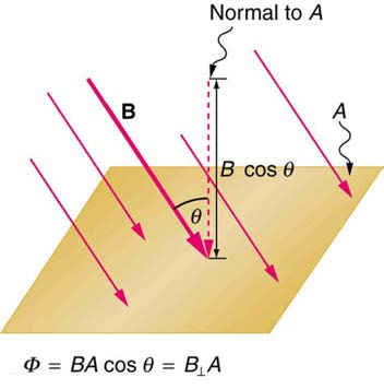
So we see that changing the magnitude or direction of a magnetic field produces an emf. Experiments revealed that there is a crucial quantity call