College Physics (2012) by Manjula Sharma, Paul Peter Urone, et al - HTML preview
Download the book in PDF, ePub, Kindle for a complete version.
20.5 Alternating Current versus Direct Current
Alternating Current
Most of the examples dealt with so far, and particularly those utilizing batteries, have constant voltage sources. Once the current is established, it is
thus also a constant. Direct current (DC) is the flow of electric charge in only one direction. It is the steady state of a constant-voltage circuit. Most
well-known applications, however, use a time-varying voltage source. Alternating current (AC) is the flow of electric charge that periodically
reverses direction. If the source varies periodically, particularly sinusoidally, the circuit is known as an alternating current circuit. Examples include the
commercial and residential power that serves so many of our needs. Figure 20.16 shows graphs of voltage and current versus time for typical DC
and AC power. The AC voltages and frequencies commonly used in homes and businesses vary around the world.
Figure 20.16 (a) DC voltage and current are constant in time, once the current is established. (b) A graph of voltage and current versus time for 60-Hz AC power. The voltage
and current are sinusoidal and are in phase for a simple resistance circuit. The frequencies and peak voltages of AC sources differ greatly.
CHAPTER 20 | ELECTRIC CURRENT, RESISTANCE, AND OHM'S LAW 711
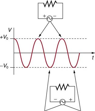
Figure 20.17 The potential difference V between the terminals of an AC voltage source fluctuates as shown. The mathematical expression for V is given by
V = V 0 sin 2 π ft .
Figure 20.17 shows a schematic of a simple circuit with an AC voltage source. The voltage between the terminals fluctuates as shown, with the AC
voltage given by
V
(20.38)
= V 0 sin 2 π ft,
where V is the voltage at time t , V 0 is the peak voltage, and f is the frequency in hertz. For this simple resistance circuit, I = V/R , and so the AC current is
I
(20.39)
= I 0 sin 2 π ft,
where I is the current at time t , and I 0 = V 0 /R is the peak current. For this example, the voltage and current are said to be in phase, as seen in
Figure 20.16(b).
Current in the resistor alternates back and forth just like the driving voltage, since I = V/R . If the resistor is a fluorescent light bulb, for example, it
brightens and dims 120 times per second as the current repeatedly goes through zero. A 120-Hz flicker is too rapid for your eyes to detect, but if you
wave your hand back and forth between your face and a fluorescent light, you will see a stroboscopic effect evidencing AC. The fact that the light
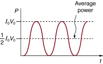
output fluctuates means that the power is fluctuating. The power supplied is P = IV . Using the expressions for I and V above, we see that the
time dependence of power is P = I 0 V 0 sin2 2 π ft , as shown in Figure 20.18.
Making Connections: Take-Home Experiment—AC/DC Lights
Wave your hand back and forth between your face and a fluorescent light bulb. Do you observe the same thing with the headlights on your car?
Explain what you observe. Warning: Do not look directly at very bright light.
Figure 20.18 AC power as a function of time. Since the voltage and current are in phase here, their product is non-negative and fluctuates between zero and I 0 V 0 . Average power is (1 / 2) I 0 V 0 .
We are most often concerned with average power rather than its fluctuations—that 60-W light bulb in your desk lamp has an average power
consumption of 60 W, for example. As illustrated in Figure 20.18, the average power P ave is
(20.40)
P ave = 12 I 0 V 0.
This is evident from the graph, since the areas above and below the (1 / 2) I 0 V 0 line are equal, but it can also be proven using trigonometric
identities. Similarly, we define an average or rms current I rms and average or rms voltage V rms to be, respectively,
712 CHAPTER 20 | ELECTRIC CURRENT, RESISTANCE, AND OHM'S LAW
(20.41)
I rms = I 02
and
(20.42)
V rms = V 0.
2
where rms stands for root mean square, a particular kind of average. In general, to obtain a root mean square, the particular quantity is squared, its
mean (or average) is found, and the square root is taken. This is useful for AC, since the average value is zero. Now,
P
(20.43)
ave = I rms V rms,
which gives
(20.44)
P ave = I 0 ⋅ V 0 = 1
2
2 2 I 0 V 0,
as stated above. It is standard practice to quote I rms , V rms , and P ave rather than the peak values. For example, most household electricity is 120
V AC, which means that V rms is 120 V. The common 10-A circuit breaker will interrupt a sustained I rms greater than 10 A. Your 1.0-kW microwave
oven consumes P ave = 1.0 kW , and so on. You can think of these rms and average values as the equivalent DC values for a simple resistive
circuit.
To summarize, when dealing with AC, Ohm’s law and the equations for power are completely analogous to those for DC, but rms and average values
are used for AC. Thus, for AC, Ohm’s law is written
(20.45)
I rms = V rms
R .
The various expressions for AC power P ave are
P
(20.46)
ave = I rms V rms,
2
(20.47)
P ave = V rms
R ,
and
2
(20.48)
P ave = I rms R.
Example 20.9 Peak Voltage and Power for AC
(a) What is the value of the peak voltage for 120-V AC power? (b) What is the peak power consumption rate of a 60.0-W AC light bulb?
Strategy
We are told that V rms is 120 V and P ave is 60.0 W. We can use V rms = V 02 to find the peak voltage, and we can manipulate the definition of
power to find the peak power from the given average power.
Solution for (a)
Solving the equation V rms = V 02 for the peak voltage V 0 and substituting the known value for V rms gives
(20.49)
V 0 = 2 V rms = 1.414(120 V) = 170 V.
Discussion for (a)
This means that the AC voltage swings from 170 V to –170 V and back 60 times every second. An equivalent DC voltage is a constant 120 V.
Solution for (b)
Peak power is peak current times peak voltage. Thus,
⎞
(20.50)
P
1
0 = I 0 V 0 = 2⎛⎝2 I 0 V 0⎠ = 2 P ave.
We know the average power is 60.0 W, and so
P
(20.51)
0 = 2(60.0 W) = 120 W.
Discussion
So the power swings from zero to 120 W one hundred twenty times per second (twice each cycle), and the power averages 60 W.
CHAPTER 20 | ELECTRIC CURRENT, RESISTANCE, AND OHM'S LAW 713
Why Use AC for Power Distribution?
Most large power-distribution systems are AC. Moreover, the power is transmitted at much higher voltages than the 120-V AC (240 V in most parts of
the world) we use in homes and on the job. Economies of scale make it cheaper to build a few very large electric power-generation plants than to
build numerous small ones. This necessitates sending power long distances, and it is obviously important that energy losses en route be minimized.
High voltages can be transmitted with much smaller power losses than low voltages, as we shall see. (See Figure 20.19.) For safety reasons, the
voltage at the user is reduced to familiar values. The crucial factor is that it is much easier to increase and decrease AC voltages than DC, so AC is
used in most large power distribution systems.
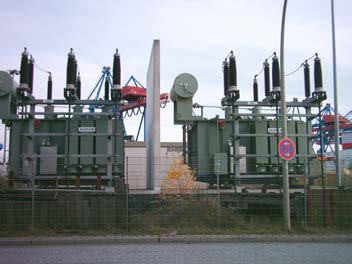
Figure 20.19 Power is distributed over large distances at high voltage to reduce power loss in the transmission lines. The voltages generated at the power plant are stepped
up by passive devices called transformers (see Transformers) to 330,000 volts (or more in some places worldwide). At the point of use, the transformers reduce the voltage
transmitted for safe residential and commercial use. (Credit: GeorgHH, Wikimedia Commons)
Example 20.10 Power Losses Are Less for High-Voltage Transmission
(a) What current is needed to transmit 100 MW of power at 200 kV? (b) What is the power dissipated by the transmission lines if they have a
resistance of 1.00 Ω ? (c) What percentage of the power is lost in the transmission lines?
Strategy
We are given P ave = 100 MW , V rms = 200 kV , and the resistance of the lines is R = 1.00 Ω . Using these givens, we can find the
current flowing (from P = IV ) and then the power dissipated in the lines ( P = I 2 R ), and we take the ratio to the total power transmitted.
Solution
To find the current, we rearrange the relationship P ave = I rms V rms and substitute known values. This gives
(20.52)
I rms = P ave
V
= 100×106 W = 500 A.
rms
200×103 V
Solution
Knowing the current and given the resistance of the lines, the power dissipated in them is found from P
2
ave = I rms R . Substituting the known
values gives
2
(20.53)
P ave = I rms R = (500 A)2(1.00 Ω ) = 250 kW.
Solution
The percent loss is the ratio of this lost power to the total or input power, multiplied by 100:
(20.54)
% loss= 250 kW
100 MW × 100 = 0.250 %.
Discussion
One-fourth of a percent is an acceptable loss. Note that if 100 MW of power had been transmitted at 25 kV, then a current of 4000 A would have
been needed. This would result in a power loss in the lines of 16.0 MW, or 16.0% rather than 0.250%. The lower the voltage, the more current is
needed, and the greater the power loss in the fixed-resistance transmission lines. Of course, lower-resistance lines can be built, but this requires
larger and more expensive wires. If superconducting lines could be economically produced, there would be no loss in the transmission lines at
all. But, as we shall see in a later chapter, there is a limit to current in superconductors, too. In short, high voltages are more economical for
transmitting power, and AC voltage is much easier to raise and lower, so that AC is used in most large-scale power distribution systems.
It is widely recognized that high voltages pose greater hazards than low voltages. But, in fact, some high voltages, such as those associated with
common static electricity, can be harmless. So it is not voltage alone that determines a hazard. It is not so widely recognized that AC shocks are often
more harmful than similar DC shocks. Thomas Edison thought that AC shocks were more harmful and set up a DC power-distribution system in New
York City in the late 1800s. There were bitter fights, in particular between Edison and George Westinghouse and Nikola Tesla, who were advocating
the use of AC in early power-distribution systems. AC has prevailed largely due to transformers and lower power losses with high-voltage
transmission.

714 CHAPTER 20 | ELECTRIC CURRENT, RESISTANCE, AND OHM'S LAW
PhET Explorations: Generator
Generate electricity with a bar magnet! Discover the physics behind the phenomena by exploring magnets and how you can use them to make a
bulb light.
Figure 20.20 Generator (http://cnx.org/content/m42348/1.4/generator_en.jar)
20.6 Electric Hazards and the Human Body
There are two known hazards of electricity—thermal and shock. A thermal hazard is one where excessive electric power causes undesired thermal
effects, such as starting a fire in the wall of a house. A shock hazard occurs when electric current passes through a person. Shocks range in severity
from painful, but otherwise harmless, to heart-stopping lethality. This section considers these hazards and the various factors affecting them in a
quantitative manner. Electrical Safety: Systems and Devices will consider systems and devices for preventing electrical hazards.
Thermal Hazards
Electric power causes undesired heating effects whenever electric energy is converted to thermal energy at a rate faster than it can be safely
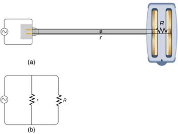
dissipated. A classic example of this is the short circuit, a low-resistance path between terminals of a voltage source. An example of a short circuit is
shown in Figure 20.21. Insulation on wires leading to an appliance has worn through, allowing the two wires to come into contact. Such an undesired contact with a high voltage is called a short. Since the resistance of the short, r , is very small, the power dissipated in the short, P = V 2 / r , is very large. For example, if V is 120 V and r is 0.100 Ω , then the power is 144 kW, much greater than that used by a typical household appliance.
Thermal energy delivered at this rate will very quickly raise the temperature of surrounding materials, melting or perhaps igniting them.
Figure 20.21 A short circuit is an undesired low-resistance path across a voltage source. (a) Worn insulation on the wires of a toaster allow them to come into contact with a
low resistance r . Since P = V 2 / r , thermal power is created so rapidly that the cord melts or burns. (b) A schematic of the short circuit.
One particularly insidious aspect of a short circuit is that its resistance may actually be decreased due to the increase in temperature. This can
happen if the short creates ionization. These charged atoms and molecules are free to move and, thus, lower the resistance r . Since P = V 2 / r ,
the power dissipated in the short rises, possibly causing more ionization, more power, and so on. High voltages, such as the 480-V AC used in some
industrial applications, lend themselves to this hazard, because higher voltages create higher initial power production in a short.
Another serious, but less dramatic, thermal hazard occurs when wires supplying power to a user are overloaded with too great a current. As
discussed in the previous section, the power dissipated in the supply wires is P = I 2 R w , where R w is the resistance of the wires and I the current flowing through them. If either I or R w is too large, the wires overheat. For example, a worn appliance cord (with some of its braided wires
broken) may have R w = 2.00 Ω rather than the 0.100 Ω it should be. If 10.0 A of current passes through the cord, then
P = I 2 R w = 200 W is dissipated in the cord—much more than is safe. Similarly, if a wire with a 0.100 - Ω resistance is meant to carry a few
amps, but is instead carrying 100 A, it will severely overheat. The power dissipated in the wire will in that case be P = 1000 W . Fuses and circuit
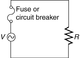
breakers are used to limit excessive currents. (See Figure 20.22 and Figure 20.23.) Each device opens the circuit automatically when a sustained current exceeds safe limits.
CHAPTER 20 | ELECTRIC CURRENT, RESISTANCE, AND OHM'S LAW 715
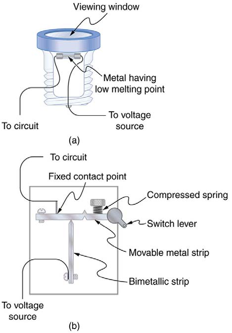
Figure 20.22 (a) A fuse has a metal strip with a low melting point that, when overheated by an excessive current, permanently breaks the connection of a circuit to a voltage
source. (b) A circuit breaker is an automatic but restorable electric switch. The one shown here has a bimetallic strip that bends to the right and into the notch if overheated.
The spring then forces the metal strip downward, breaking the electrical connection at the points.
Figure 20.23 Schematic of a circuit with a fuse or circuit breaker in it. Fuses and circuit breakers act like automatic switches that open when sustained current exceeds desired limits.
Fuses and circuit breakers for typical household voltages and currents are relatively simple to produce, but those for large voltages and currents
experience special problems. For example, when a circuit breaker tries to interrupt the flow of high-voltage electricity, a spark can jump across its
points that ionizes the air in the gap and allows the current to continue flowing. Large circuit breakers found in power-distribution systems employ
insulating gas and even use jets of gas to blow out such sparks. Here AC is safer than DC, since AC current goes through zero 120 times per
second, giving a quick opportunity to extinguish these arcs.
Shock Hazards
Electrical currents through people produce tremendously varied effects. An electrical current can be used to block back pain. The possibility of using
electrical current to stimulate muscle action in paralyzed limbs, perhaps allowing paraplegics to walk, is under study. TV dramatizations in which
electrical shocks are used to bring a heart attack victim out of ventricular fibrillation (a massively irregular, often fatal, beating of the heart) are more
than common. Yet most electrical shock fatalities occur because a current put the heart into fibrillation. A pacemaker uses electrical shocks to
stimulate the heart to beat properly. Some fatal shocks do not produce burns, but warts can be safely burned off with electric current (though freezing
using liquid nitrogen is now more common). Of course, there are consistent explanations for these disparate effects. The major factors upon which
the effects of electrical shock depend are
1. The amount of current I
2. The path taken by the current
3. The duration of the shock
4. The frequency f of the current ( f = 0 for DC)
Table 20.3 gives the effects of electrical shocks as a function of current for a typical accidental shock. The effects are for a shock that passes through the trunk of the body, has a duration of 1 s, and is caused by 60-Hz power.
716 CHAPTER 20 | ELECTRIC CURRENT, RESISTANCE, AND OHM'S LAW
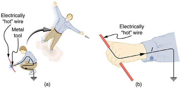
Figure 20.24 An electric current can cause muscular contractions with varying effects. (a) The victim is “thrown” backward by involuntary muscle contractions that extend the
legs and torso. (b) The victim can’t let go of the wire that is stimulating all the muscles in the hand. Those that close the fingers are stronger than those that open them.
Table 20.3 Effects of Electrical Shock as a Function of Current[3]
Current
Effect
(mA)
1
Threshold of sensation
5
Maximum harmless current
Onset of sustained muscular contraction; cannot let go for duration of shock; contraction of chest muscles may stop breathing during
10–20
shock
50
Onset of pain
100–300+
Ventricular fibrillation possible; often fatal
300
Onset of burns depending on concentration of current
Onset of sustained ventricular contraction and respiratory paralysis; both cease when shock ends; heartbeat may return to normal;
6000 (6 A)
used to defibrillate the heart
Our bodies are relatively good conductors due to the water in our bodies. Given that larger currents will flow through sections with lower resistance
(to be further discussed in the next chapter), electric currents preferentially flow through paths in the human body that have a minimum resistance in
a direct path to earth. The earth is a natural electron sink. Wearing insulating shoes, a requirement in many professions, prohibits a pathway for
electrons by providing a large resistance in that path. Whenever working with high-power tools (drills), or in risky situations, ensure that you do not
provide a pathway for current flow (especially through the heart).
Very small currents pass harmlessly and unfelt through the body. This happens to you regularly without your knowledge. The threshold of sensation is
only 1 mA and, although unpleasant, shocks are apparently harmless for currents less than 5 mA. A great number of safety rules take the 5-mA value
for the maximum allowed shock. At 10 to 20 mA and above, the current can stimulate sustained muscular contractions much as regular nerve
impulses do. People sometimes say they were knocked across the room by a shock, but what really happened was that certain muscles contracted,
propelling them in a manner not of their own choosing. (See Figure 20.24(a).) More frightening, and potentially more dangerous, is the “can’t let go”
effect illustrated in Figure 20.24(b). The muscles that close the fingers are stronger than those that open them, so the hand closes involuntarily on
the wire shocking it. This can prolong the shock indefinitely. It can also be a danger to a person trying to rescue the victim, because the rescuer’s
hand may close about the victim’s wrist. Usually the best way to help the victim is to give the fist a hard knock/blow/jar with an insulator or to throw an
insulator at the fist. Modern electric fences, used in animal enclosures, are now pulsed on and off to allow people who touch them to get free,
rendering them less lethal than in the past.
Greater currents may affect the heart. Its electrical patterns can be disrupted, so that it beats irregularly and ineffectively in a condition called
“ventricular fibrillation.” This condition often lingers after the shock and is fatal due to a lack of blood circulation. The threshold for ventricular
fibrillation is between 100 and 300 mA. At about 300 mA and above, the shock can cause burns, depending on the concentration of current—the
more concentrated, the greater the likelihood of burns.
Very large currents cause the heart and diaphragm to contract for the duration of the shock. Both the heart and breathing stop. Interestingly, both
often return to normal following the shock. The electrical patterns on the heart are completely erased in a manner that the heart can start afresh with
normal beating, as opposed to the permanent