Operation and Maintenance Small Heating Systems by Department of the Army - HTML preview
Download the book in PDF, ePub, Kindle for a complete version.
CHAPTER 3
FUEL BURNING EQUIPMENT
Section I. COAL STOKERS
3-1. General.
sion for driving the coal feed worm and electric
Stokers may be divided into four general classes:
motors supplying power for coal feed and air
underfeed, spreader, travelling or chain grate, and
supply. Air for combustion is admitted to the fuel
overfeed. Generally, domestic type boilers use
through tuyeres at the top of the retort. The retort
single-retort underfeed stokers and therefore, only
may be either round or rectangular. The stoker
this type is discussed.
feeds coal to the furnace intermittently in accord-
ance with temperature or pressure demands. A
3-2. Single-retort underfeed stokers.
special time or holdfire control is used to maintain
a fire during periods when heat is not required.
This unit consists essentially of a coal hopper, a
Figure 3-1 shows a typical arrangement.
screw for conveying coal from hopper to retort, a
fan which supplies air for combustion, a transmis-
Figure 3-1. Single retort screw feed stoker.
3-3. Operation.
and damage it. If too heavy, poor air distribution
Two main causes of excessive outage and mainte-
will result, causing spotty, uneven fire, holes in the
nance are sustained or frequent overloading of
fuel bed, smoke, and reduced efficiency. The
stoker and operating with insufficient draft. Where
correct depth of the fuel bed above the top of the
prolonged overloading is unavoidable, good
retort may be anywhere from 4 to 8 inches,
operation and careful attention to maintenance are
depending upon analysis and burning characteristics
important.
of the coal used.
a. Fire. Following are the main points to keep in
b. Draft. Check with draft gauge and a carbon
mind for maintaining a good fire.
dioxide (C0 ) indicator.
2
(1) Keep fire out of retort. This condition can
(1) Operate with a slight draft, preferably not
result from a fuel bed which is too thin, from
less than 0.02 inch water gauge just above the fuel
banking with insufficient fuel or from running with
bed. Positive pressure will cause excessive tem-
an empty hopper.
peratures at grates and lower wall areas.
(2) Avoid working the fire too much. If the fuel
(2) Maintain a proper supply of air at all times.
bed requires leveling off, use a light rake or bar on
Either too much or too little air will reduce
the surface of the fire. Never slice the fire as is done
efficiency and capacity.
in hand firing by pushing a bar under the fire and
(3) Do not force the stoker beyond the capacity
raising it through the fuel bed.
of the stack to carry away flue gases.
(3) Be sure to feed sufficient fuel when bank-
(4) Keep wind boxes properly sealed to prevent
ing. It may be necessary to renew the fuel supply
leakage of air into the ash pit and furnace.
during long banking periods.
(5) If the draft is insufficient, check leaks in
(4) The depth of the fuel bed is very important.
setting and losses through boiler and flue connec-
If too thin, the fire may burn down into the retort
tions. Check the position of the boiler damper.
3-1
TM 5-642
c. Cleaning.
moving parts. Where movement is transmitted by a
(1) Remove siftings from wind boxes often
shear pin or safety release be sure there is no
enough to prevent any possibility of fire under the
binding which prevents protective device from
hearth. Frequency of cleaning depends upon type of
serving its function. Make repairs or replacements
fuel used, but wind boxes should be inspected
promptly.
often.
c. When the stoker is shut down, make a thor-
(2) Keep the front of the stoker clean to pre-
ough inspection. Check for wear on moving parts
vent contamination of lubricants and excessive wear
and check alignment. Check condition of dump
on moving parts.
grates. On stokers equipped with moving grate
d. Lubrication. Use proper lubricants at suffi-
bars, check movement of bars to see that proper
ciently frequent intervals at all points requiring
clearances are maintained. Overall clearances to
lubrication to avoid unnecessary outages and ex-
provide for elongation of grate bars should be 1 ½
cessive maintenance. Prepare a definite schedule for
inches on small stokers, and up to 2 inches on
lubrication and adhere to it regularly. Manu-
larger stokers.
facturer*s literature should be consulted when set-
d. Inspection and maintenance procedures for
ting up the lubrication schedule.
anthracite coal stokers in domestic type installations
e. Lay-up. When stokers are to be out of service
are similar to that for bituminous coal stokers
for long periods of time, remove coal from the
previously described. However, some units are so
hopper and feed screw. Drain the transmission and
arranged that ash is automatically discharged to an
fill with the correct amount and viscosity the oil
ashpit, from which removal may be either manual or
recommended by the manufacturer. Clean and oil
by small automatic conveyor units. The tuyere
the motor using a good grade of electric motor oil.
surface of anthracite burners is made of either
Clean and paint the coal hopper with a rust-resist-
formed perforated sheet metal or cast metallic
ant paint; mix sawdust and fuel oil or crankcase
plates or rings with suitable air ports. In some
drainings and fill the feed-screw housing and retort.
instances tuyere surfaces are made of radially
This prevents moisture from forming on the feed
placed cast elements. Ignited coal is forced out
screw during idle periods. Have the controls
toward the periphery of the tuyere by the incoming
cleaned and adjusted as necessary by a competent
coal, and as burning is completed, the ash is
mechanic.
discharged by gravity from the ash ring into an
ashpit under the stoker retort. To avoid discharge
3-4. Inspection and maintenance procedures.
of unburned coal to the ashpit, adjust the rate of
Following is a description of good practices for in-
coal feed and air supply carefully.
spection and maintenance of coal stokers:
a. Inspect all accessible parts of the stoker often.
3-5. Troubleshooting underfeed stokers.
Inspect thoroughly at scheduled intervals.
A troubleshooting chart for underfeed stokers is in
b. During routine and daily inspections, look es-
appendix B.
pecially for loose bolts and loose connections in
Section II. HAND-FIRED COAL BURNERS
3-6. General.
stallations covered by this manual. Primary air
In coal burning installations, units may be hand
enters the lower portion of the furnace and passes
fired using either updraft or downdraft type fur-
up through the fuel bed. Stationary grate bars
naces. In both types, coal is fed manually onto
permit primary air to rise and ash to drop through.
grade bars forming the bed of the furnace. There
The fire must be cleaned manually with special
are limitations to the combustion capacity obtain-
tools. Sometimes dumping grates are used which
able with hand firing in a single heating unit; this
firing method is employed only with the smallest
permit mechanical removal of ash and refuse
units.
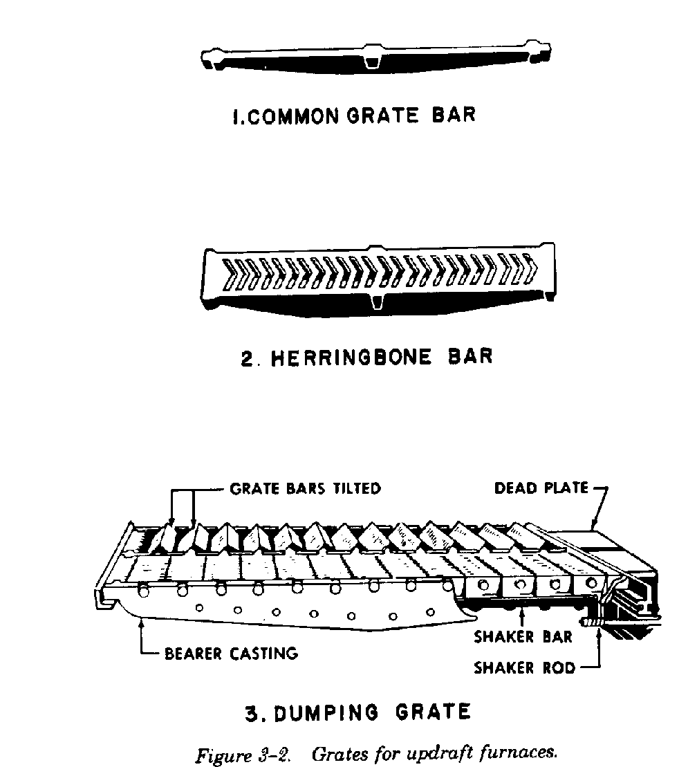
without opening fire doors. Typical grates used in
this type of furnace are shown in figure 3-2.
3-7. Furnace types.
a. Updraft furnace. Updraft type furnaces are
most commonly used in the types of military in-
3-2
TM 5-642
rise and the ashes to drop through.
(2) The herringbone or tupper bar (figure 3-2.2)
is about six inches wide with side flanges to prevent
warping. Each bar has V-shaped openings running
the length of the bar for passage of air and ash.
(3) The dumping grate (figure 3-2.3) permits
removal of the ash and refuse without opening the
firing doors and also reduces the amount of labor
required. Tools used to handle the fire are the hoe,
slice bar, and rake. The hoe and slice bar are used
to clean the fire and break the clinkers. The rake is
used to level off the fuel bed. The bridge wall keeps
the fire on the grates, assists in mixing the air and
gases, and directs them over the heating surface.
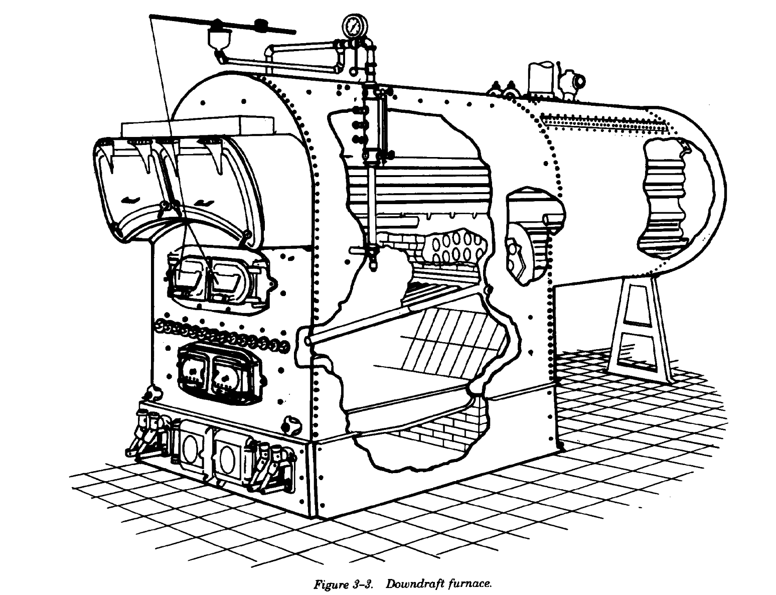
b. Downdraft furnace. The downdraft furnace
(figure 3-3) has both an upper and lower grate and
gets its name from the fact that primary air passes
down through the fuel on the upper grate. The
upper grate consists of a series of tubes which
extend from the front water leg to a header in the
rear. This header extends from one side water leg
to the other, and supports a refractory wall which
forms the back of the downdraft furnace. The lower
grate is formed by common grate bars or by a
regular shaking grate. Coal is fired through the top
The grate, which supports the fuel bed and admits
doors onto the upper or downdraft grate where it
air for combustion, is made up of a number of bars
burns. Incandescent fuel drops through to the lower
supported at the rear by the bridge wall and at the
grate where it keeps a bright fire. Air is admitted
front by a dead plate which, in turn, is supported by
above the upper grate and mixes with the distilled
the brickwork. The grate bars are held in place by
gases from the coking coal as it passes down
their own weight. The types of grates commonly
through the upper grate. The incandescent fuel bed
used for updraft furnaces are the common grate
on the lower grate helps to complete the
bar, herringbone or tupper bar and dumping grate.
combustion of volatile matter given off by the coal
(1) The common grate bar (figure 3-2.1) is usu-
and reduces emission of smoke from the boiler.
ally about three feet long and three inches deep at
This type of furnace cannot be used where high
its center. The width varies from ¾ inch at the top
rates of firing are necessary.
to ¾ inch at the bottom. This grate allows the air to
3-3
TM 5-642
3-8. Operation.
bed. After the distillation is complete, the
In hand firing, the best condition of the fuel bed is
remaining carbonized fuel is pushed back and
obtained when coal is fired frequently, in small
distributed over the bed. This method, while
amounts, with proper distribution; when caked
effective, does not permit obtaining high rates of
masses are broken up immediately; and when ash
combustion compared to the other methods.
and clinkers are not allowed to clog the bed. In
(1) The best firing condition for a hand fired
general, there are three methods of hand firing.
furnace is obtained when fresh coal is added at or
a. Spread firing. A small amount of the fresh
shortly after completion of distillation of the previ-
coal is distributed evenly each time over the entire
ous charge. Optimum intervals between firing are
surface of the bed. This method is commonly
approximately ten minutes for bituminous coals,
adopted with anthracite and other low-volatile
and slightly less frequently for less volatile semi-
coals.
bituminous and anthracite coals.
b. Alternate firing. New coal is placed on select-
(2) The bed thickness for best results depends
ed areas of the grate each time. The coal may be
on many factors, including the kind, size and con-
placed alternately on one half of the grate, on al-
dition of coal, the characteristics of the ash, the
ternate strips, or on alternate spots. This method of
draft available and the loading. In general, with
stoking is particularly suited to non-caking coals.
natural draft, bed thicknesses range from four to
c. Coking-firing. Fresh fuel is placed on the
eight inches with run-of-mine bituminous coal and
front edge of the fuel bed and allowed to cake
with anthracite buckwheat. Bed thicknesses range
there, the volatile matter passing back over the hot
from 10 to 14 inches for semibituminous coals.
With heavy loading, however, it may be desirable to
3-4
TM 5-642
use a relatively thin fuel bed to increase the flow of
cases, bed thickness for a given type of furnace and
primary air obtainable with the available draft. In all
coal is best determined by experiment.
Section III. OIL BURNERS
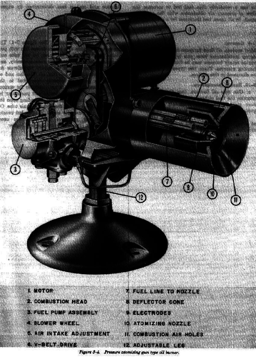
3-9. General.
valve, and atomizing nozzle. (See figure 3-4.) The
Most modern oil fired furnaces and boilers used at
air system consists of a power-driven fan with pro-
Army installations have gun type burners. Hori-
vision to throttle the air inlet, an air tube sur-
zontal rotary burners may be found on some older
rounding the nozzle and electrode assembly, and
heating systems. These two types of burners will be
vanes or other means to induce turbulence for
discussed in this section.
proper mixing of air and fuel oil. The fan and oil
pump are generally directly connected to the motor.
3-10.
Burner descriptions.
Atomizing nozzles are available for various spray
patterns and oil rates to suit particular installations.
a. Gun type oil burners. Gun type oil burners
Flame shapes vary depending upon the design of
atomize the fuel either by oil pressure (high-pres-
the air exit at the end of the air tube. Oil pressures
sure gun) or by low-pressure air (low-pressure
are generally about 100 psi, but considerably
gun).
greater pressures are sometimes used. Burner
(1) High-pressure gun burners. The oil system
output ranges from 0.5 gph and higher.
of a high-pressure atomizing burner consists of a
strainer, pump, pressure-regulating valve, shut-off
3-5
TM 5-642
3-6
TM 5-642
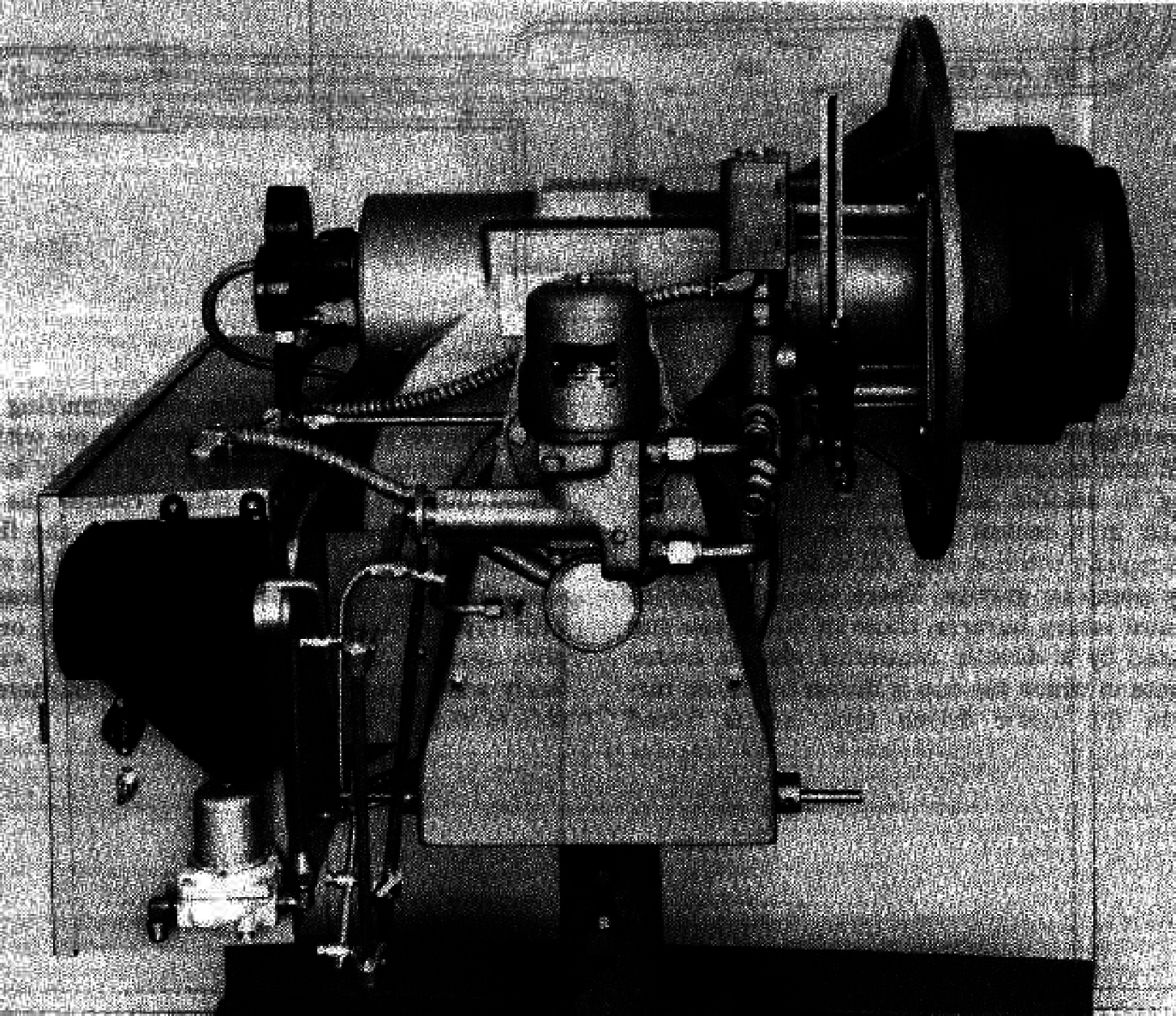
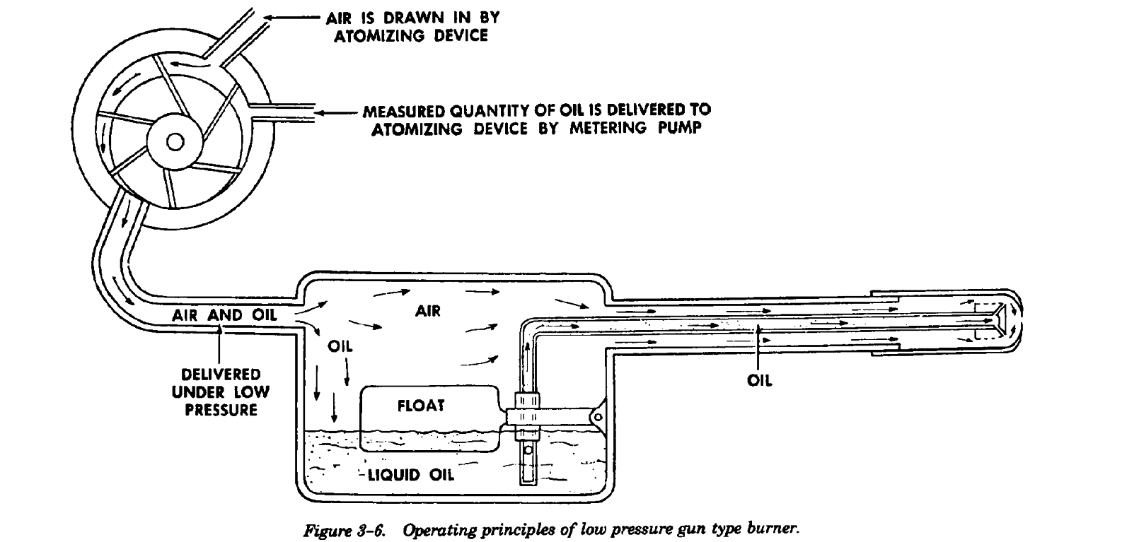
(2) Low-pressure gun burners. This gun type
means to deliver the air and oil to the nozzle. The
burner uses a portion of the combustion air at rel-
oil pump delivers the fuel oil at low pressure. The
atively low pressures to mix with the fuel oil at the
nozzle opening is relatively large because of the low
nozzle orifice. Expansion of the compressed air
pressure and the increased volume of the air-oil
froths or emulsifies the oil and a fine spray is de-
mixture. Electric ignition is almost exclusively used.
livered into the combustion chamber. The form and
Electrodes are located near the nozzle, but out of
parts of the low pressure air-atomizing burner, as
the path of the oil spray. Minimum burner output is
shown in figures 3-5 and 3-6 may be similar to
approximately 20 gph so that this type burner is
those of the high-pressure atomizing burner except
used only for very large furnaces.
for the addition of a small air compressor and
Figure 3-5. Air atomizing gun type burner.
3-7
TM 5-642
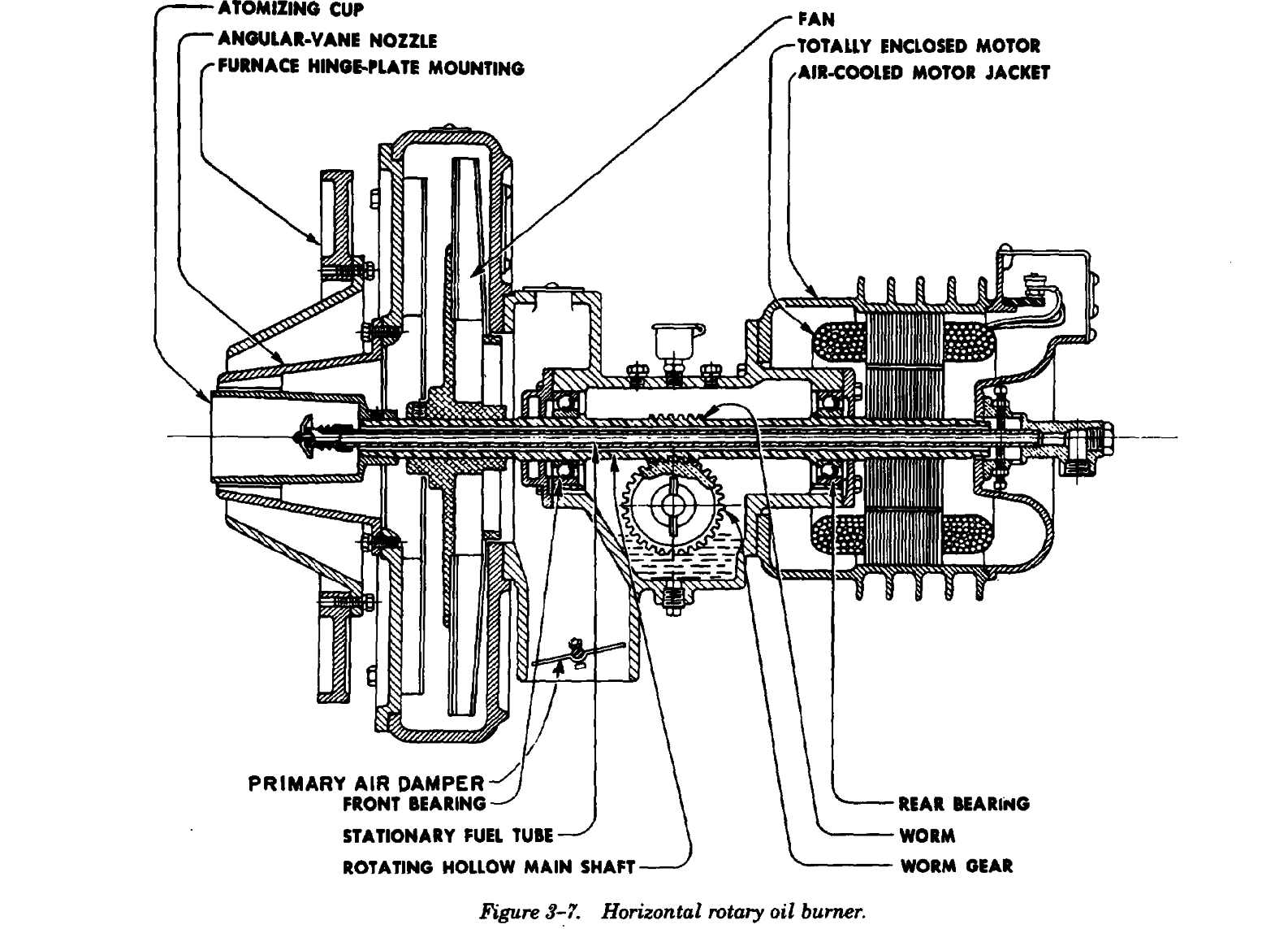
b. Horizontal rotary burners. Horizontal rotary
surrounding the atomizing cup which shapes the
burners (figure 3-7) originally designed for com-
flame and mixes the air with oil. In the turbine
mercial and industrial use, are used for domestic
driven type, part of the air is first passed through a
heating in smaller sizes. In this burner, oil is
turbine which rotates the cup, and is then directed
atomized in a conical pattern by being sprayed from
to properly shape the flame. Horizontal rotary
a rapidly rotating cup. Oil is delivered to the cup by
burners are constructed to swing away from the
pump or gravity. There are two types of horizontal
furnace for inspection and cleaning. This type of
rotary burners, those in which the cup is rotated by
burner employs gas-electric or gas pilot ignition and
a directly connected electric motor and those in
operates satisfactorily with a fairly wide range of
which the cup is driven by an air turbine. In the
fuels. Large size burners are able to atomize heavier
motor driven type, air is forced through vanes
oils.
3-8
TM 5-642
3-11.
Ignition procedures.
(2) Partly close air shutter.
Domestic oil burners vaporize and atomize the oil
(3) Check pressure gauge and petcock installa-
and deliver a predetermined quantity of oil and air
tion.
to the combustion chamber for combustion. Oil
(4) Make a cold contact in primary burner con-
burners for boilers and warm air furnaces operate
trol or stack switch by tilting contact carrier to left
automatically and maintain a desired temperature.
so contact closes. See instructions from supplier of
a. Oil pressure. Pressure must be sufficient to
primary control for this operation.
properly atomize the fuel oil and to provide flow of
(5) Close burner switch with thermostat and
fuel to the atomizing head at a minimum velocity
limit control calling for heat.
consistent with efficient operation. Generally, No. 1
(6) Open petcock to expel air from system.
oil will work well in small burners provided it
Close when oil flow is clear.
contains a lubricant to lubricate the pump. A com-
(7) If burner stops before oil reaches nozzle, let
paratively heavy oil will allow flow through a given
safety element in stack control cool before pushing
nozzle somewhat in excess of the rating stamped on
button to restart. Do not hold relay in because
the nozzle. Heavy oils require 100 psi pressures.
safety element will become overheated.
High pressure plus heavy oil tends to raise the flow
(8) Slowly open air adjustment until fire burns
rate considerably above the nozzle marking. If the
clean.
flow is too heavy, a smaller nozzle should be
(9) If oil initially discharges into the firebox
installed.
without igniting because of ignition difficulty or
b. Burner starting The following procedure
other cause, oil will soak into the soft brick. Be
should be followed to start a gun-type or horizontal
sure relief door is open. Properly ventilate combus-
rotary burner.
tion chamber after any misfire. When burner does
(1) Set draft for 0.02 to 0.04 inch water gauge.
ignite, shut burner off immediately and allow sur-
3-9
TM 5-642
plus oil to burn off. Oil-soaked brick will cause the
operates at high flame, and changes to low flame
burner to rumble and puff for a few minutes until
when room temperatures reach a desired point. A
oil has completely burned out. After any misfire,
modification to this system provides for three
personnel should stand to one side of the opened
ranges of firing.
relief door to avoid injury from possible backfire.
c. Continuous. In the continuous system, the
(10) Make final air adjustment after burner has
flame burns continuously but the rate is regulated
been running long enough to warm the fire-pot.
manually or automatically to meet the heating load.
Look through the barometric draft regulator with a
droplight. Reduce the supply of burner air until
3-13.
Inspection and maintenance of oil
smoke can be seen passing through the light ray in
burners.
the smokepipe. Then open the air adjustment until
a. Equipment. Each serviceman should have the
smoke disappears.
items listed below to start or to service gun-type
(11) After the burner has been visually adjusted
and horizontal rotary burners.
and allowed to run for approximately 30 minutes,
(1) Pressure gauge set consisting of 150 psi
reduce the stack draft until there is just enough
pressure gauge, fittings and petcock for purging air
pressure in the firebox to prevent possible increases
from oil line when starting the burner. Pressure
under unfavorable draft conditions. The draft
gauges with ranges as high as 600 psi may be
regulator helps maintain a constant draft regardless
required for high-pressure gun burners.
of outside weather conditions. Adjust the draft by
(2) A full set of Allen setscrew wrenches for the
properly setting the adjuster. Too little draft is
bypass plugs and for adjusting the nozzle holder
likely to cause firebox pressure, odors in the
and electrodes. Use only a socket wrench of proper
building and possible smoke or smothering of the
size for the nozzle. An open end S-wrench is
flame. Excessive draft accentuates the effect of a
required for nozzle holders.
possible leak, lowers the percentage of CO in the
2
(3) Small screw driver for adjusting pressure at
flue gas, and in turn reduces the overall efficiency
regulator and for installing and servicing the
of the unit. After burner flame and draft are
thermostat.
properly adjusted, flue-gas analysis should show a
(4) Pipe dope for use with oil lines. Be sure that
CO content o