Multiservice Procedures for Well-Drilling Operations by Department of the Army, Navy and the Air Force - HTML preview
Download the book in PDF, ePub, Kindle for a complete version.
drilling but before reaching the desired
depth. (Use this procedure when drilling in
loose, unconsolidated materials.) When
installing the casing before the well screen,
such as surface casing, the casing must be
larger than the screen. Therefore, use a
larger drill bit than the one used to complete
the screen portion of the borehole. The
decision to use surface casing should be
made before mobilizing and should be
based on the geologic information about the
site.
a. Surface Casing. Use the following
steps to install the surface casing:
Step 1. Drill the borehole to a predetermined depth, and remove all the cuttings by circulating the drilling fluid. Withdraw the drill string and remove the bit.
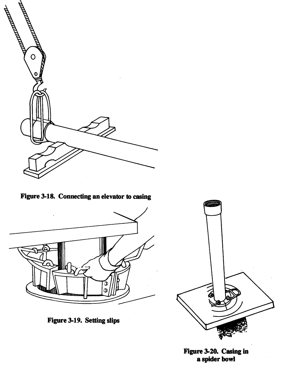
Step 2. Set the kelly back in the cradle. Connect the elevators to the first section of surface casing that is lifted over the borehole by using a casing elevator and the hoist or
by using a sand line (Figure 3-18).
Step 3. Lower the casing into the well and set the slips (Figure 3- 19), which suspend the
casing in the well, in the spider bowl (Figure 3-20).
Step 4. Disconnect the elevator. Hoist the next casing section with the elevator, and place it in the first section. Join the two sections. Slightly lift the string of casing, and remove the elevator from the lower section. Lower the casing, and repeat the process until you suspend the last casing section in the well.
Step 5. Grout the casing in place with a cement grout. After the grout sets (about 24
hours), resume drilling operations using a drill bit that will fit inside the surface casing.
Drill the well to the desired depth, and case and screen the lower section of the well, using the single-string method.
3-18
FM 5-484/NAVFAC P-1065/AFMAN 32-1072
3-19


FM 5-484/NAVFAC P-1065/AFMAN 32-1072
b. Screening. You can use the following method to install screens: Step 1. Place a casing section in the well. Cap the casing on the lower end so materials from the bottom of the well will not enter the well.
Step 2. Suspend a screen section over the well and attach the screen section to the casing section.
Step 3. Lower the screen and casing section. Suspend them in the well either by the elevator resting on the rotary table or by slips in the spider bowl.
Step 4. Add casing until the screen reaches the desired depth.
Chapter 5 discusses other methods of screening.
c. Filtering and Backfilling. The last procedure when installing screen and casing is to place a gravel-pack filter around the screen and backfill material around the casing. If you place the screen in material such as gravel or very coarse sand, you may not need a gravel pack. Place the gravel filter material around the outside of the casing. Deposit the material to the bottom of the well. Add gravel to about 5 feet from the top of the screen. (Use the sounding method to determine the level of the gravel.) Add impervious backfill around the casing from the gravel pack to about 10 to 20
feet from the surface. If you use grout instead of impervious material, add a couple of feet of clay above the gravel to prevent the grout from entering the gravel filter. Bring the grout to the surface.
3-12. Well Development Frequently, when a well is frost installed, the efficiency (production per foot of drawdown) is not satisfactory, and you must develop the well either by pumping or surging or both. Developing a well removes the remaining drilling fluid, breaks down any filter cake buildup on the borehole wall, and flushes the fines in the formation (adjacent to the grovel pack) into the well. Make sure that you pump the well of all fine sediments and sand with an airlift before installing the submersible pump. If you do not, the pump and components will wear out prematurely. To develop a well, pump or blow the drilling fluid out of the well. Agitate the water in the well to produce an alternating in and out flow through the well screen (or gravel pack). There are several methods available to develop a well. The simplest method follows: Step 1. Attach a weighted plunger or surge block to the sand line. Lower the surge block into the well below the water level but above the screen.
Step 2. Lift the block and then drop the block 3 to 4 feet, repeatedly, to surge the well.
Continue this action for several minutes.
Step 3. Remove the surge block and lower a bailer into the well. All of the sand that was pulled into the well is bailed from the sand trap.
Step 4. Repeat the process, noting the amount of sand brought into the well each time.
Development is complete when 5 milligrams or less of sand per liter of sampled water is removed.
Step 5. Sanitize the well with calcium hypochlorite.
3-13. Sanitary Seals. All wells must have a sanitary seal to prevent contamination from surface runoff. Mix cement grout and place it in the annulus between the well casing and the borehole wall.
Extend the grout from the surface to the top of the backfill material (30-foot minimum). You should also pour a concrete platform (about 4 feet by 4 feet) around the casing at the surface with the casing extended at least 1 foot above the surface. The upper surface of the slab and the surrounding area 3-20


FM 5-484/NAVFAC P-1065/AFMAN 32-1072
should be gently sloping away from the well for better drainage. In addition to a surface grouting, you need to install a well seal (a type of bushing or packing gland) to prevent foreign materials from entering the inside of the well casing. You normally install the well seal when you install the pump, which is after you complete all development, testing, and disinfecting.
3-14. Pumping Tests. After installing a well, you should perform a pumping test. The test will show you if the well can produce the required amount of water. If the well is considered permanent, the pumping test should help you evaluate any future performance deterioration. Evaluation parameters are flow rate, time, and drawdown in the well.
Before you start the test, place a sounding device, such as an M-Scope, in the well to measure the water level during the test. You must also measure and regulate the flow rate during the test.
The most proficient way to measure the flow rate is with a flow meter. However, you can use a calibrated container and a stop watch. Use the following procedures to perform the pumping test: Step 1. Temporarily install a pump in the well below the anticipated drawdown depth but above the screen.
Step 2. Measure the static water level and start the pump. During the test, one team member should monitor the flow rate and try to keep the flow rate constant.
Step 3. Record the drawdown with the flow rate. Take early readings quickly; then spread out the readings as testing progresses. An ideal reading schedule would be the initial reading and then a reading at 30 seconds, 1 minute, 2 minutes, 4 minutes, 8 minutes, 15 minutes, 30 minutes, 1 hour, 2 hours, and so forth. You must record the exact times you take readings of the drawdown and flow-rate measurements. The length of a test usually depends on the purpose of the well, the urgency for water, and the time available.
On small water supplies, you can perform an adequate evaluation in 4 to 5 hours. For large, permanent supplies, tests could take from days to weeks. The GPM, footage of drawdown, and available drawdown give an immediate indication of the well’s capacity.
If the pump from the well-completion kit is capable of producing more water than the well can, you should put a throttle or a valve on the pump. Doing so will help regulate water extraction and will prevent pump damage.
Step 4. Set and adjust the pump. The well is now ready for use or for connecting to a treatment, storage, and distributions system.
3-21

FM 5-484/NAVFAC P-1065/AFMAN 32-1072
Chapter 4
Pumps
4-1. Fundamentals.
a. Pump Types. Pumps maybe classified according to use (for shallow or deep wells), design (variable or positive displacement), or method of operation (rotary, reciprocating, centrifugal, jet, or airlift). This chapter deals with shallow- and deep-well pumps. Shallow-well pumps (suction-lift pumps) are normally installed above ground, on or near the top of the well casing. Deep-well pumps are installed in the well casing with the pump inlets submerged below the pumping level. These inlets are always under a positive head and do not require suction to move or pump the water.
b. Selection Criteria. Consider the following items when selecting a pump: Size of the well.
Quantity of water to be pumped.
Drawdown and pumping levels.
Type of available power.
Yield of the well.
Estimated total pumping head.
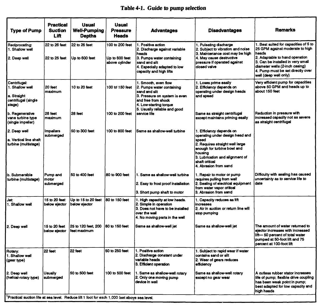
Well yield is frequently overlooked when selecting a pump for small wells. Installing a pump that can handle a large discharge capacity can either temporarily drain a small well or exceed the maximum possible suction lift. Therefore, pumping requirements and well characteristics must be
matched to determine the optimum pump for each installation. Table 4-1 (page 4-2) provides a
general guide for use in pump selection. Military well drillers deploying with well-completion kits will normally use the deep-well submersible pumps that are supplied with the kits.
4-2. Shallow-Well Pumps. These pumps are limited to the depth from which they can lift water.
At sea level, the practical limit is 22 to 25 feet for most pumps. This value decreases about 1 foot for each 1,000-foot increase in elevation above sea level. The operative principle of a shallow-well pump is similar to drinking through a strew. A partial vacuum is created, and the difference between the pressure inside the straw and the liquid outside the straw forces the liquid upward to a new equilibrium.
A pump exhausts air from the intake line, thus lowering the pressure on the intake side below atmospheric pressure. The atmospheric pressure on the water in the well then forces the water up through the suction line into the pump. The atmospheric pressure is the only force available to lift water to the pump. At sea level, the force is about 14.7 pounds per square inch (psi) (about 34 feet of water). The maximum is never reached because pumps are not 100 percent efficient and because other factors (water temperature and friction or resistance to flow in the suction pipe) reduce the suction lift. Since a partial vacuum is required in the suction line, the line must be airtight if the pumps are to function properly. Threaded joints must be carefully sealed with pipe-joint compound and all connections to the pump must be tight.
4-1
FM 5-484/NAVFAC P-1065/AFMAN 32-1072
4-2


FM 5-484/NAVFAC P-1065/AFMAN 32-1072
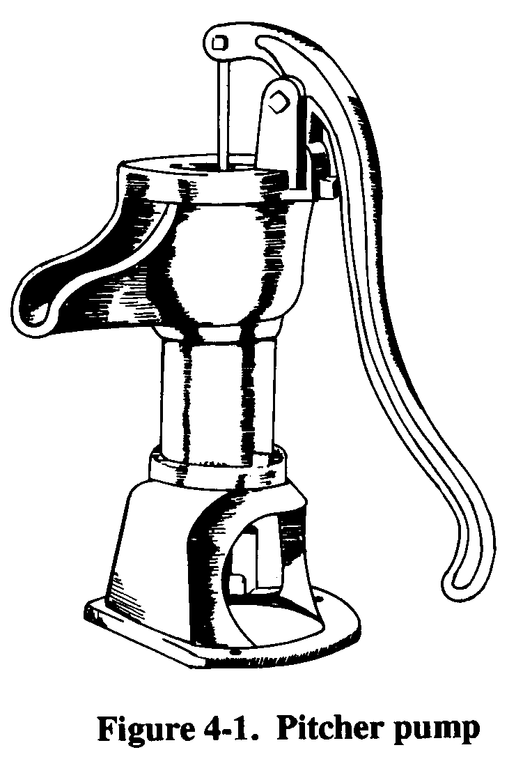
a. Pitcher Pump. This is a surface-mounted, reciprocating or single-acting piston pump (Figure 4-1). The pump has a hand-operated plunger that works in a cylinder designed to be set on top of the well casing. The suction pipe screws into the bottom of the cylinder. The plunger has a simple ball valve that opens on the downstroke and closes on the upstroke. Usually, a check valve at the lower end of the cylinder opens on the upstroke of the pump and closes on the downstroke.
continuous upstroke and downstroke actions result in a pulsating flow of water out of the discharge pipe. By lifting the pump handle as high as possible, the check valve (lower end of the cylinder) will tilt when the plunger is forced down on top of the valve. Tilting the check valve allows the pump and suction line to drain.
To reprime the pump after draining, pour water in
the cylinder from the top of the pump. To maintain
the pitcher pump, renew the plunger, check the valve
leathers, and clean the suction pipe. Clean the suction
pipe when it becomes clogged with sand, gravel, or
other material. The pump will be noisy and the pump
handle may fly up when released during the
downstroke.
b. Rotary Pump. These pumps use a system of
rotating gears (Figure 4-2) to create a suction at the
inlet and force a water stream out of the discharge.
The gears’ teeth move away from each other at the
inlet port. This action causes a partial vacuum and the
water in the suction pipe rises. In the pump, the water
is carried between the gear teeth and around both sides
of the pump case. At the outlet, the teeth moving
together and meshing causes a positive pressure that
forces the water into the discharge line.
4-3

FM 5-484/NAVFAC P-1065/AFMAN 32-1072
In a rotary gear pump, water flows continuously and steadily with very small pulsations. The pump size and shaft rotation speed determine how much water is pumped per hour. Gear pumps are generally intended for low-speed operation. The flowing water lubricates all internal parts.
Therefore, the pumps should be used for pumping water that is free of sand or grit. If sand or grit does flow through the gears, the close-fitting gear teeth will wear, thus reducing pump efficiency or lifting capacity.
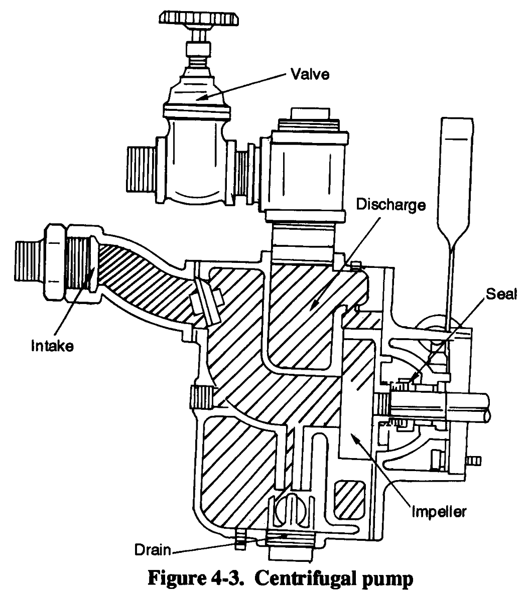
c. Centrifugal Pump. These are variable displacement pumps in which water flows by the centrifugal force transmitted to the pump in designed channels of a rotating impeller (Figure 4-3).
A closed case, with a discharge opening, surrounds the impeller. The case has a spiral-shaped channel for the water. The channel gradually widens towards the outlet opening. As water flows through the channel, speed decreases and pressure increases. The hydraulic characteristics of the pump depend on the dimensions and shape of the water passages of the impeller and the case.
The centrifugal pump works as follows:
Water enters the pump at the center of the impeller and is forced out by centrifugal force.
(You may have to fill the pump and suction pipe with water before starting the pump.) The expelled water forces the water in the casing out through the discharge pipe, producing a partial vacuum in the center.
Atmospheric pressure acts on the surface of the water in the well and forces more water up the suction pipe and into the impeller to replace the expelled water.
(1) Head.
Head is the
pressure against which a pump
must work the suction-lift and
friction losses and the system
pressure that the pump must
develop. If the head is increased
and the speed is unchanged, the
flow rate will decrease. To
increase the flow rate, you must
increase the speed or decrease the
head. If you increase the head
beyond the pump’s (shutoff head)
capacity, water will not be
pumped. The impeller only churns
the water inside the case; the
energy expended heats the water
and the pump. If such action
continues, enough heat may
develop to boil the water and
generate steam causing the
impeller to rotate in vapor rather
than water. With no coolant, the
bearings seize, resulting in severe
pump and possible motor damage.
4-4

FM 5-484/NAVFAC P-1065/AFMAN 32-1072
(2) Connections. You may have to use several pumps to meet head or flow requirements. You can connect the pumps either in series or in parallel. If you connect two centrifugal pumps in series (the discharge of the first connected to the suction of the second), the discharge capacity stays the same. However, the head capacity is the sum of both pumps head capacities. The increased head capacity is only available as discharge head. You will not gain any appreciable increase in suction lift. You can obtain the same effect by using a multistage pump that contains two or more impellers within one casing.
If you connect two centrifugal pumps in parallel (both suctions are connected to the intake line and both discharges connected to the discharge line), the discharge head is the same as that of the individual pumps. The discharge capacity is close to the sum of the capacities of both pumps. The increased flow rates result in extra friction losses that prevent the combined flows from being the exact sum of the two pumps.
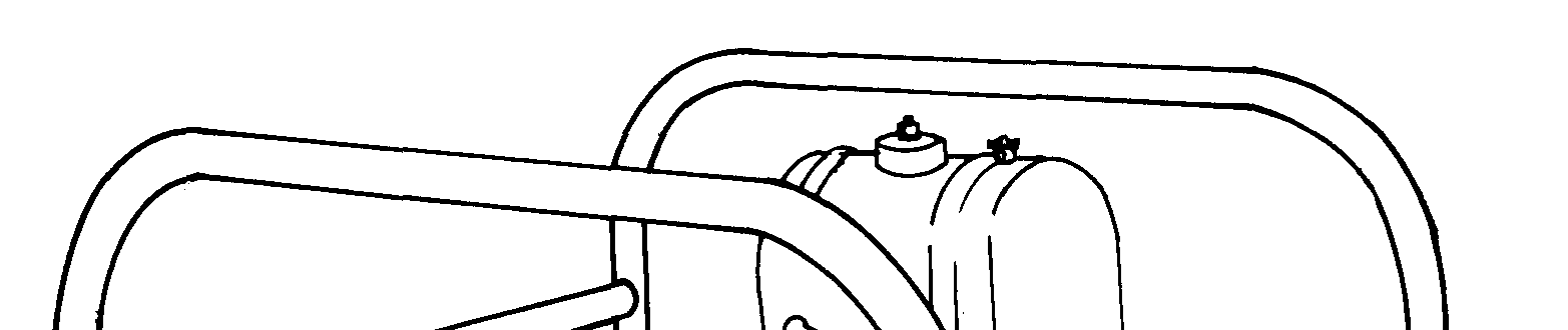
d. Self-Priming Pump. This pump has a priming chamber that makes repriming unnecessary when the pump is stopped for any reason other than an intentional draining. The pump is mounted
on a frame with and driven by a two-cylinder, three-horsepower military standard engine (Figure
and keyed to the engine stub shaft. A self-adjusting mechanical seal prevents water from leaking between the pump and the engine. The pump is designed for optimum performance with a suction lift of 10 feet. You can operate the pump at greater suction lifts, but the capacity and efficiency of the unit are reduced proportionately.
(1) Installation. Install the pump as close to the source of water supply as possible to minimize the required suction lift. Install full-sized suction piping and keep friction losses as low as possible by using the least possible number of pipe fittings (elbows, bents, unions). To ensure that joints do not leak use pipe cement or teflon tape on all joints. If you use a suction hose, try to ensure that the hose is as airtight as possible. If you have to remove the suction or discharge piping or hose frequently, you should make the connections with unions to reduce wear on the pump housing.
(2) Priming. To prime the pump, remove the priming plug on top of the pumping case, and pour water into the pump case to the discharge-opening level. Failure to fill the priming chamber may prevent priming. If the pump takes longer than 5 minutes to prime, a mechanical problem exists. A self-priming pump is normally primed from a 10-foot suction lift in 2 minutes or less, depending on the length and size of the suction pipe. If you use a valve in the discharge line, you must open it wide during priming.
If the pump fails to prime, look for the following:
Plugged priming hole.
Air leak in suction pipe or hose.
Collapse of lining suction hose.
Plugged end of suction pipe or suction strainer.
Lack of water in pump housing.
Clogged, worn-out, or broken impeller.
Worn or damaged seal.
4-5


FM 5-484/NAVFAC P-1065/AFMAN 32-1072
4-3. Deep-Well Pumps.
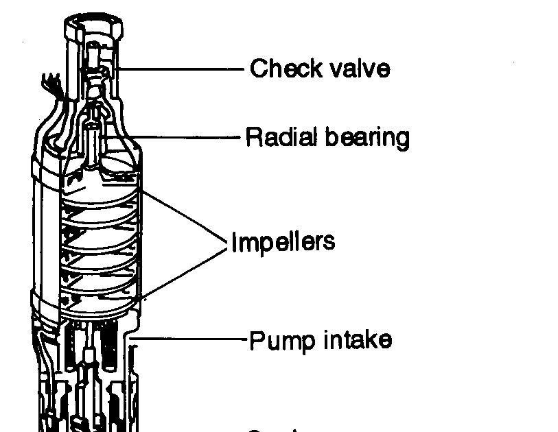
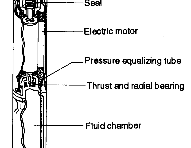
a. Submersible Pump. This is a centrifugal pump closely coupled with an electric motor that can operate underwater. The pump is typically multistage containing two or more impellers (depending on head requirements) housed in a bowl assembly. Because the system is designed for underwater operations, it has a waterproof electric motor, watertight seals, electric cables and connections. The motor is located beneath the bowl assembly with the water intake screen between the two units.
Military well-completion kits contain the submersible pump (Figure 4-5). The pump produces
50 GPM at 600 feet and is powered by a 15-horsepower, 460-volt, 3-phase electric motor. The pump comes with 700 feet of electrical conductor cable and 660 feet of 2-inch drop hose that supports the pump and brings the water to the surface distribution system. Currently, the submersible pump is the standard in deep-well, high-production systems.
4-6


FM 5-484/NAVFAC P-1065/AFMAN 32-1072
The following improvements have made the
submersible pump a reliable pump:
Motors, cables, and seals have very low
maintenance requirements.
Noise levels are reduced because the motor
is located in the well.
Motor operates at a cooler temperature
because it is submerged.
System does not require long drive shafts and
bearings, so maintenance problems and
deviations in vertical well alignment are not
critical factor when using this pump.
The main disadvantage with the pump is that the
entire pump and motor assemblies must be removed
from the well if repairs or services are required.
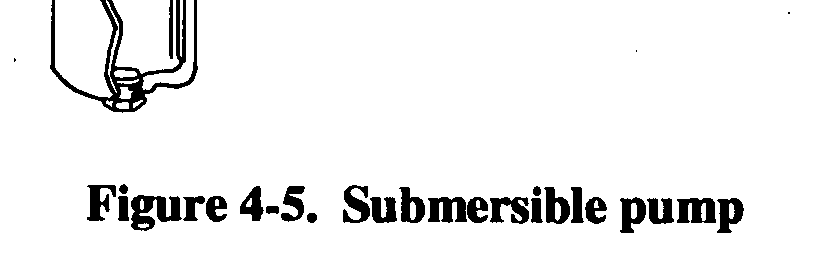
b. Turbine Pump. The turbine (line shaft) pump is
a shaft-driven, centrifugal pump. The pump is hung in
a well at the lower end of a string of pipe called the column pipe. The shaft, which drives the pump, runs through the column pipe and extends from the pump to the ground surface where it is connected to a pump-head assembly. Bearings in the column pipe are used to stabilize the shaft. The turbine
pump (Figure 4-6, page 4-8) is a multistage pump containing several impellers or bowl assemblies.
The main advantage to the turbine pump is the accessibility to the power source. The power source is either a hollow-shaft electric motor or a reciprocating engine connected by a right-angle drive and is located above ground. The main disadvantages are maintenance requirements for the shaft and bearings and the requirement that the well be vertical with no deviations for installation.
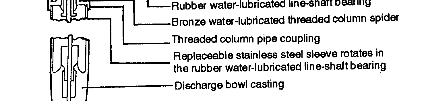
c. Helical-Rotor Pump. This pump is a positive-displacement-, rotary-screw-, or progressing-
cavity-type pump (Figure 4-7, page 4-9). The pump is designed for relatively low-capacity, high-
lift wells that are 4 inches or larger in diameter. The main elements of the pump are a highly polished, stainless-steel helical rotor, a single-thread worm; and an outer rubber stator. The rotor is located in the stator. During the rotation process, the rotor forces a continuous stream of water forward along the cavities in the stator producing a uniform flow. The helical-rotor pump is designed to produce 50 GPM at 1,800 revolutions per minute (RPM) against a 250-foot head.
4-7


FM 5-484/NAVFAC P-1065/AFMAN 32-1072
4-8

FM 5-484/NAVFAC P-1065/AFMAN 32-1072
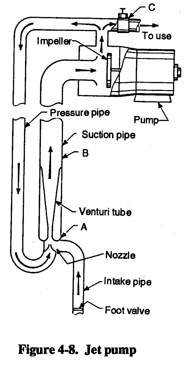
d. Jet Pump. This pump is a
combination of a surface centrifugal
pump, down-hole nozzle, and venturi
arrangement (Figure 4-8). It c