Maintenance of Waterfront Facilities by Department of the Army - HTML preview
Download the book in PDF, ePub, Kindle for a complete version.
apron), or a combination of the two. It extends outward
restoration of a facility to such a condition that it can be
from the shore into a harbor or other navigable waters to
effectively utilized for its designed purpose. The repair
permit berthing along one or both sides of its length.
is accomplished by overhaul, reprocessing, or
replacement of constituent parts or materials that have
1.4.2.2 Wharf. A wharf or quay (Figure 1-2) is a deck
deteriorated by action of the elements or usage and
structure supported above the water on piles (open type),
have not been corrected through maintenance. Repair
can be incorporated in a concurrent modernization
program.
1-4
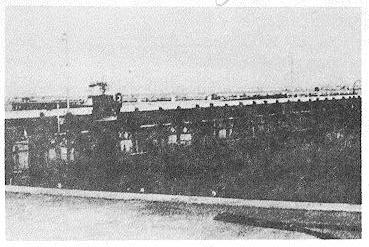
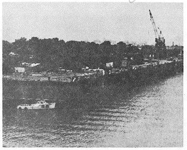
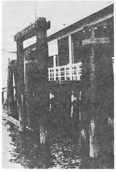
Figure 1-1. Open-type pier.
a solid-fill structure retained by bulkheads (closed), or a
combination of the two. It runs parallel to the shore and
is connected to it at more than one point (usually
continuously) to provide berthing normally along one
side.
Figure 1-3. Example of a dolphin.
1.4.2.4 Fleet Mooring. A fleet mooring is an offshore
ship anchoring system that consists of a ground tackle
arrangement of chain or cable, sinkers, and anchors or
other holding devices placed on the bottom of an
anchorage. It is connected by means of a riser chain (or
chains) to a buoy (riding on the surface of the water)
Figure 1-2. Example of a wharf.
whereby a ship can be made fast to the buoy.
Maintenance of fleet moorings is described in Reference
1.4.2.3 Dolphin. A dolphin (Figure 1-3) is a structure
1-17; it is mentioned in this manual only to identify fleet
usually consisting of one or a group of piles. It is placed
moorings as an important type of waterfront structure
near piers and wharves or in turning basins and ship
requiring regular maintenance.
channels (1) to guide vessels into their moorings, (2) to
fend vessels away from structures, shoals, or the shore,
1.4.2.5 Drydocking System. A drydocking system is a
(3) to support navigation aids, or (4) to moor a vessel.
facility for exposing the normally underwater portion of a
ship for construction, inspection, modification, repair, or
1-5
hull maintenance. Several different types are listed
below.
1.4.2.5.1 Graving Dock. A graving dock (Figure 1-4) is
a fixed basin usually of stone masonry, concrete, or
piling cells adjacent to the water's edge. It can be
closed off from the waterway by a movable watertight
barrier (entrance caisson or flap gate). It can, therefore,
be pumped dry, allowing a ship to settle down on
blocking set on the dock floor.
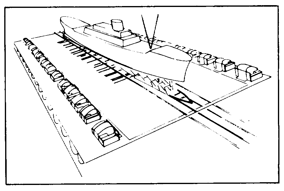
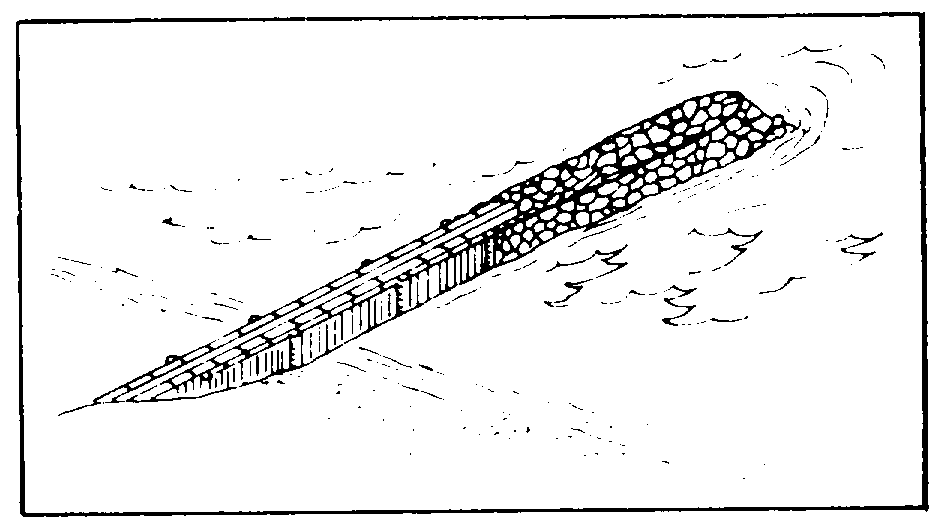
Figure 1-5. Example of a marine railway.
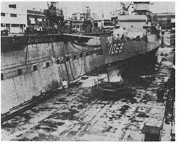
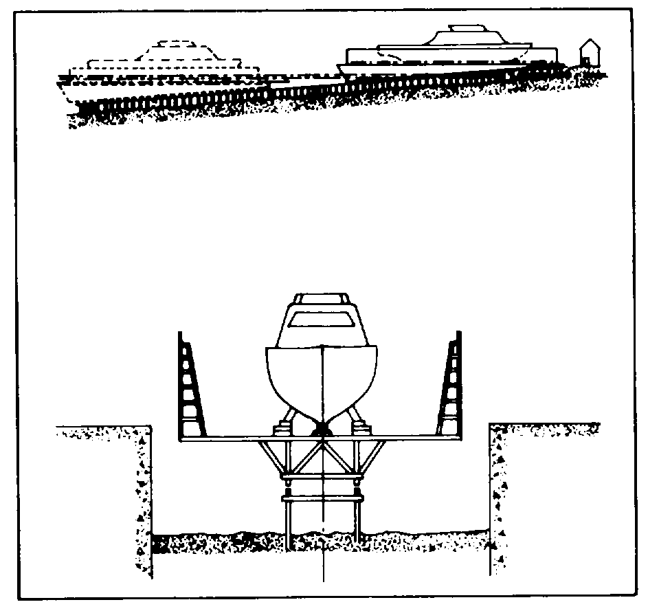
1.4.2.5.4 Vertical Lift. A vertical lift drydock (Figure 1-
6) is a platform which is lowered into the water to
receive a ship, and then elevated out of the water by
electrically, pneumatically, or hydraulically powered
hoisting equipment.
Figure 1-4. Graving dock with ship installed.
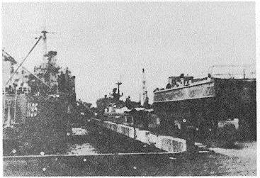
1.4.2.6 Quay Wall. A quay wall (Figure 1-7) is a barrier
1.4.2.5.2 Floating Drydock. A floating drydock is a
of steel, stone, concrete, or wood that supports an
ship or U-shaped structure that can be submerged by
embankment or fill built as a part of a waterfront
flooding to permit a vessel to enter and then later be
structure.
pumped dry to raise the vessel out of the water.
Maintenance and operation of floating drydocks will not
be discussed in this manual.
1.4.2.5.3 Marine Railway. A marine railway (Figure 1-
5) consists of an inclined groundway extending into the
water, a mobile ship cradle on wheels or rollers,
groundway ship cradle tracks, hoisting machinery, and
chains or cables for hauling the ship cradle endwise or
sidewise.
Figure 1-6. Example of a vertical lift
drydock.
1-6
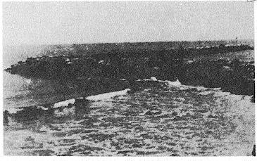
1.4.2.8 Jetty. These structures, which are located at the
entrance to a harbor or in a river estuary, extend from
the shore into deeper water to prevent the formation of
sandbars and to direct and confine the flow of water due
to currents and tides (Figure 1-9). Jetties are usually
constructed of mounds of large rubble to an elevation
several feet above high tide. They are generally lower
in height than breakwaters and are designed to offer
less resistance to waves than breakwaters and seawalls.
Jetties should be dense enough to prevent sand from
entering the entrance channel.
Figure 1-7. A quaywall.
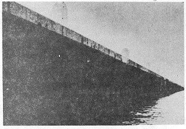
1.4.2.7 Mole. Moles are normally earthen structures
that extend outward from shore into the navigable
waters of the harbor (Figure 1-8). The sides and
offshore end of a mole are retained or protected by
riprap, sheet-pile bulkhead of either prestressed or
reinforced concrete, or a gravity-type wall of either
masonry or concrete. Such a structure is sometimes
used as a breakwater. Generally, the level top is
appreciable in area and may contain paved roads,
Figure 1-9. Example of a jetty.
railroads, and crane trackage. If the sides and offshore
end of a mole are protected by either a bulkhead or a
1.4.2.9 Breakwater. These are substantial structures,
gravity-type wall, the structure can be used to berth
located at the outer limits of a harbor or anchorage, to
vessels, provided the depth of water is adequate.
protect the inner waters against the effects of heavy
seas and winds and to ensure safe mooring, operating,
loading, or unloading of shipping within the harbor
(Figure 1-10). These durable barriers usually consist of
rubble-mound structures and are often covered with
heavy, large rocks or reinforced concrete armor units.
There are three general types of breakwaters,
depending on type of exposed face: (1) vertical, (2)
partly vertical and partly inclined, or (3) inclined.
Breakwaters may be either detached from the shore or
shore-connected.
Figure 1-8. Example of a mole.
1-7
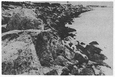
1.4.2.11 Seawall. These are massive structures, built
along and parallel to the shoreline, that are designed to
protect coastal areas against erosion caused by wave
action and flooding during heavy seas (Figure 1-12).
The seawalls are constructed of rubble-mound, granite
masonry, or reinforced concrete. They are usually
supplemented with steel or concrete sheet pile driven
into the beach and strengthened by wales and brace-
type piles.
Figure 1-10. Example of the placement of
a breakwater.
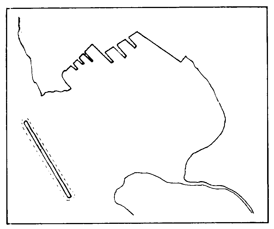
1.4.2.10. Groin. These structures control the rate of
shifting sand by influencing offshore currents and wave
action in a manner such that erosion of the shoreline is
prevented or minimized (Figure 1-11). Generally, the
Figure 1-12. Example of a seawall.
longtime effect of groins is an increase in the width of
the beach. These narrow structures may be
perpendicular to the shoreline and are constructed of
large rocks (at least 1 ton each), precast concrete units,
reinforced or prestressed concrete piles, steel sheet
piles, or timber cribbing filled with rock. The most
common type of groin is the high, dense one that is
designed to catch the drifting sand until the sand is
forced around the offshore end.
Figure 1-11. A groin.
1-8
SECTION 5.
1.5.1 PROGRAMMING. The maintenance program for
waterfront structures and other harbor facilities shall be
1.5.3 CAUSES OF DETERIORATION. The
developed to include the prevention and prompt
deterioration of waterfront facilities is caused
detection of deficiencies or damage and the quick
PLANNING by exposure to destructive forces, such as:
performance of maintenance or repairs in an
economical and workable manner. Replacement or
(1)
Attack by fungi, termites, and marine
repair of damaged parts should be made as soon as
organisms
possible because when one item is not working, the
(2)
Corrosion
remaining parts are more easily damaged. These
(3)
Mechanical damage, including the impact
requirements are essential to the maintenance
and pressure of ships and cargo and the abrasive action
standards established by higher authority.
of sand, ice, and debris
(4)
Erosion due to wind and wave action,
1.5.2 ECONOMIC REQUIREMENT. In the
tides, water currents, rain, snow, sleet and ice, and
maintenance of waterfront facilities thorough
freezing and thawing.
consideration shall be given to the overall economy of
the facility. Of particular importance is a complete study
1.5.4 INSPECTION. Waterfront facilities shall be
of the replacement cost of the facility in relation to the
inspected periodically to determine the extent of the
expected life span and the cost of repairs. Other factors
maintenance and repair work required. References 1-1
to be considered include the following: prompt detection
and 1-16 set up the Navy's guidelines for inspection and
of deficiencies or damage and the expeditious
include essential information on guides, check-off forms,
performance of maintenance or repairs in an
reports, and record systems to be used in the program.
economical and workable manner. Replacement or
It is recommended that inspections be made annually of
repair of damaged components should be made as soon
all basic structures and more frequently for fenders and
as possible because of:
movable equipment, such as brows and camels.
Additional inspections may be necessary under certain
(1)
Possible obsolescence of the facility
circumstances, such as tidal waves, high tides,
(2)
The present adequacy of the facility
earthquakes, typhoons, heavy freezes, etc. Inspections
(3)
The present and future availability of
may be made from the structures, from a boat or float,
maintenance funds
or from below the water line by divers. (See Appendix A
(4)
The operational economics of downtime
for details on diver inspections.) Underwater television is
involved in major repair or replacement of facilities.
often employed in visual inspections.
1-9
SECTION 6. PREPARATION FOR WORK
1.6.1 FIELD MEASUREMENTS. During inspections,
wear, corrosion, alignment, deflection, etc. may be
1.6.3 SKETCHES. As a part of programming the
estimated. Where there is any question as to the
repairs, sketches should be made to outline clearly the
degree of hazard, an accurate engineering investigation
extent, sequence, and details of the repair operation.
shall be made. Facilities to be repaired shall be
On other than major projects, freehand sketches,
carefully measured so that construction details can be
properly dimensioned and supplemented by notes, will
designed and estimates of required materials prepared.
be sufficient to permit an experienced maintenance man
Material storage areas should be designated and laid
to carry out the work properly. All sketches should be
out at this time so that interference with traffic is
clear and legible and should normally be reproducible.
minimized. Field measurements should include the
Copies of the sketches, properly identified as to location
exact location of underground utilities so that they can
and date, should be filed with the job record and with the
be avoided or relocated as necessary.
as-built drawings.
1.6.2 AS-BUILT DRAWINGS. “As-built" drawings, if
1.6.4 CHECKING STRUCTURAL STABILITY. Any
available, should be used in programming the repairs
evidence of damage or deterioration affecting the
rather than the original drawings, because these
structural stability of any facility should be the subject of
drawings should show all deviations from the original
an immediate engineering study. This study should
design and changes made during the original
include the degree of hazard and recommendations as
construction. These drawings should be carefully
to what corrective measures are required.
compared with actual field observations to detect any
changes that might have been made after completion of
the as-built drawings.
SECTION 7. ACCESS TO WORK
1.7.1 DIVERS. No one skill is more essential to the
1.7.2 RAFTS AND/OR BARGES. Rafts or barges for
proper performance of maintenance and repair work on
general repair work should have a flat, open-deck area
waterfront structures than that of the diver. The diver, in
completely covered with planking that is reasonably tight
addition to being certified, should be experienced in
to prevent both accidents to workmen and the loss of
construction and familiar with construction tools and
tools and equipment. The rafts can be supported on
materials. The diver must also be able to report clearly
logs or pontoons. The structures should be rigid enough
and in exact detail underwater conditions (see Appendix
to withstand considerable shock. The raft should be
equipped with well-secured cleats or other means for
1-10
securing lines. Rafts should be fitted with handrails or
posts less than 4 inches by 4 inches should be used for
lifelines on the sides that are not adjacent to the work.
a scaffold, and they should be securely cross-braced.
Deck planking should be kept in repair by plugging any
Convenient access from the ground and from one level
holes and replacing broken or cracked planks. Rafts
to another should be provided by ladders or stairs that
with steel pontoons and framework should be kept
are rigidly secured. All platform levels should have well-
painted to prevent deterioration and should have
supported life rails. On the land side, supports must be
adequate fendering systems.
placed on firm ground, preferably in such a manner that
they can be wedged up or raised if necessary. If
1.7.3 SCAFFOLDS. All scaffolding shall conform to all
vehicles will pass adjacent to or near the scaffolding,
military and ASSHO safety regulations.
substantial barricades should be placed at least 3 feet
from the supports of the scaffold.
1.7.3.1 Wood Scaffolds. Wood scaffolds should be
built to suit the particular work that is to be done from
Fire extinguishers of adequate size shall be
them. They should be rigid and completely stable in
stationed near wood scaffolds to conform with fire
themselves, even when not secured to a structure. No
regulations.
less than two 10-inch-wide planks of 2-inch nominal
thickness should be used as the platform. The
1.7.3.2 Pipe Scaffolds. Pipe scaffolds should be free
unsupported span shall not exceed 10 feet. All planks
of any bent, dented, or otherwise defective members.
used for scaffold platforms should be tested
Every connector of each tier must be made tight before
immediately prior to the installation of the framework. If
the next tier is installed. Joints and connectors in pipe
no other means of testing is available, each plank
scaffolds must be tightly bolted. Scaffold supports
should be placed flat and supported at each end by a
should be maintained in a vertical position.
block 12 inches high. The plank should then be loaded
at its midpoint with twice the anticipated load on the
1.7.3.3 Hung Scaffolds. Platform planking and life rails
scaffold, and the load left on for at least 5 minutes. If
for hung scaffolds should be similar to those for built-up
visible or audible failure occurs, or if the plank remains
scaffolds. The rope or line used should be of more than
deformed after the load is removed, it should be
ample size and free of defects; it should be secured to
discarded. All scaffold planks should be free of large
cleats, bitts, a string piece, or another substantial part of
knots, shakes, splits, checks, or any other visible
the structure. The scaffolds should also be equipped
defects. All scaffold planks should be securely
with a positive mechanical or structural means of
fastened. Any scaffold plank that, by use or accident,
belaying the free end of the rope or line.
becomes broken, cracked, warped, or in any way
defective should be replaced immediately by a sound
1.7.4 LADDERS. All ladders should be made with
plank.
sound, secure rungs notched into, or passing through,
The strength of the scaffold framework should
be more than sufficient for the height of the scaffold. No
1-11
the stringers. Broken or cracked rungs should be
and redriving the sheeting further as excavation
replaced immediately. Ladders should not be painted
progresses
because this could conceal defects.
(3)
Installing breast boards around the sides
of the excavation as it progresses downward.
Wooden ladders shall be treated occasionally
(4)
Driving soldier beams and placing breast
with clear linseed oil to prevent the wood from drying
boards between them as the excavation progresses.
out. New ladders, especially those with hardwood
rungs, should be dipped in a 5% pentachlorophenol
Where excavations are necessary beneath the
solution for 3 minutes to deter rotting. If dipping is not
water table, it may be necessary to dewater the site to
possible, the solution should be brushed or sprayed on.
permit working in the dry. In such instances the major
Linseed oil need not be applied when the latter
criteria to meet are those dealing with loss of stability of
treatment has been used.
the bottom or sides of the excavation and removal of
the water (see References 1-18 through 1-20).
1.7.5 EXCAVATIONS. Excavations for repair work are
normally required for access to underground parts of a
In some cases it may be necessary to stabilize
structure. The safety of the structure during excavation
the soil prior to excavation by using, for example,
is of prime consideration. The excavation should be
electroosmosis for fine-grained soils, or freezing or
made so that the surrounding ground does not lose its
grouting to stabilize the coarser soils (see Reference 1-
own stability or such support as it may be giving to the
18).
adjacent structure. This is accomplished by:
(1)
Removing material in a manner so that a
Necessary measures should be taken and
stable, sloping bank is created around the sides of the
careful observations made to be sure mud, silt, water
excavation.
slurry, and other excavation materials do not undermine
(2)
Driving vertical wood, concrete, or steel
adjacent roads, piers, fills, tracks, and facilities.
sheeting around the sides of the area to be excavated,
SECTION 8. SAFETY
1.8.1 INSTRUCTIONS. Safety precautions and safe
conditions at the site of the work and ASSHO
maintenance practices are covered in detail in the
regulations. Safety lines should be rigged with as little
following:
slack as possible. If the slack is more than two or three
feet, a workman could be injured by even this short fall.
(1)
Always use a safety belt, never a loop of rope around a
(2)
Navy NAVFAC 5100.1 1 A [1-22]
man's body. Insist on workmen using hard hats, unless
(3)
they are clearly unnecessary, and require them to wear
safety glasses when chipping, grinding, or sandblasting.
1.8.2 PERSONAL PROTECTION. Workmen in
Safety shoes and other types of protective clothing are
hazardous locations should wear life belts or safety belts
(or both) attached to safety 1 lines according to the
1-12
frequently necessary and should be used. A respirator
normally provided in berthing areas to cushion the
should be available for use should the need arise.
impact of ships when docking. In some cases, it may be
economical to provide dolphins for additional protection
1.8.3 BARRICADES AND SAFETY LINES. All unsafe
to waterfront structures. All special problems of