Parallel Manipulators Towards New Applications by Huapeng Wu - HTML preview
Download the book in PDF, ePub, Kindle for a complete version.
Preface
V
1. Control of Cable Robots for Construction Applications
001
Alan Lytle, Fred Proctor and Kamel Saidi
2. Dynamic Parameter Identification for Parallel Manipulators
021
Vicente Mata, Nidal Farhat, Miguel Díaz-Rodríguez,
Ángel Valera and Álvaro Page
3. Quantifying and Optimizing Failure Tolerance of a Class of Parallel Manipu- 045
lators
Chinmay S. Ukidve, John E. McInroy and Farhad Jafari
4. Dynamic Model of a 6-dof Parallel Manipulator Using the Generalized
069
Momentum Approach
António M. Lopes and Fernando Almeida
5. Redundant Actuation of Parallel Manipulators
087
Andreas Müller
6. Wrench Capabilities of Planar Parallel Manipulators and their Effects Under 109
Redundancy
Flavio Firmani, Scott B. Nokleby, Ronald P. Podhorodeski and Alp Zibil
7. Robust, Fast and Accurate Solution of the Direct Position Analysis of
133
Parallel Manipulators by Using Extra-Sensors
Rocco Vertechy and Vincenzo Parenti-Castelli
8. Kinematic Modeling, Linearization and First-Order Error Analysis
155
Andreas Pott and Manfred Hiller
9. Certified Solving and Synthesis on Modeling of the Kinematics. Problems
175
of Gough-Type Parallel Manipulators with an Exact Algebraic Method
Luc Rolland
10. Advanced Synthesis of the DELTA Parallel Robot for a Specified Works-
207
pace
M.A. Laribi, L. Romdhane and S. Zeghloul
VIII
11. Size-adapted Parallel and Hybrid Parallel Robots for Sensor Guided Micro 225
Assembly
Kerstin Schöttler, Annika Raatz and Jürgen Hesselbach
12. Dynamics of Hexapods with Fixed-Length Legs
245
Rosario Sinatra and Fengfeng Xi
13. Cartesian Parallel Manipulator Modeling, Control and Simulation
269
Ayssam Elkady, Galal Elkobrosy, Sarwat Hanna and Tarek Sobh
14. Optimal Design of Parallel Kinematics Machines with 2 Degrees of Free-
295
dom
Sergiu-Dan Stan, Vistrian Maties and Radu Balan
15. The Analysis and Application of Parallel Manipulator for Active Reflector
321
of FAST
Xiao-qiang Tang and Peng Huang
16. A Reconfigurable Mobile Robots System Based on Parallel Mechanism
347
Wei Wang, Houxiang Zhang, Guanghua Zong and Zhicheng Deng
17. Hybrid Parallel Robot for the Assembling of ITER
363
Huapeng Wu, Heikki Handroos and Pekka Pessi
18. Architecture Design and Optimization of an On-the-Fly Reconfigurable
379
Parallel Robot
Allan Daniel Finistauri, Fengfeng (Jeff) Xi and Brian Petz
19. A Novel 4-DOF Parallel Manipulator H4
405
Jinbo Wu and Zhouping Yin
20. Human Hand as a Parallel Manipulator
449
Vladimir M. Zatsiorsky ad Mark L. Latash
21. Mobility of Spatial Parallel Manipulators
467
Jing-Shan Zhao, Fulei Chu and Zhi-Jing Feng
22. Feasible Human-Spine Motion Simulators Based on Parallel Manipulators 497
Si-Jun Zhu, Zhen Huang and Ming-Yang Zhao
1
Control of Cable Robots for
Construction Applications
Alan Lytle, Fred Proctor and Kamel Saidi
National Institute of Standards and Technology
United States of America
1. Introduction
The Construction Metrology and Automation Group at the National Institute of Standards
and Technology (NIST) is conducting research to provide standards, methodologies, and
performance metrics that will assist the development of advanced systems to automate
construction tasks. This research includes crane automation, advanced site metrology
systems, laser-based 3D imaging, calibrated camera networks, construction object
identification and tracking, and sensor integration and process control from Building
Information Models. The NIST RoboCrane has factored into much of this research both as a
robotics test platform and a sensor/target positioning apparatus. This chapter provides a
brief review of the RoboCrane platform, an explanation of control algorithms including the
NIST GoMotion controller, and a discussion of crane task decomposition using the Four
Dimensional/Real-time Control System approach.
1.1 The NIST RoboCrane
RoboCrane was first developed by the NIST Manufacturing Engineering Laboratory’s
(MEL) Intelligent Systems Division (ISD) in the late 1980s as part of a Defense Advanced
Research Project Agency (DARPA) contract to stabilize crane loads (Albus et al., 1992). The
basic RoboCrane is a parallel kinematic machine actuated through a cable support system.
The suspended moveable platform is kinematically constrained by maintaining tension due
to gravity in all six support cables. The support cables terminate in pairs at three vertices
attached to an overhead support. This arrangement provides enhanced load stability over
beyond traditional lift systems and improved control of the position and orientation (pose)
of the load. The suspended moveable platform and the overhead support typically form two
opposing equilateral triangles, and are often referred to as the “lower triangle” and “upper
triangle,” respectively.
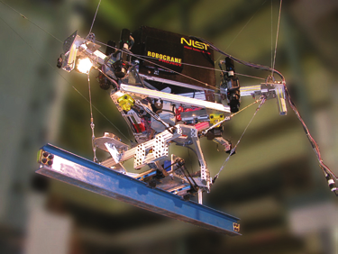
The version of RoboCrane used in this research is the Tetrahedral Robotic Apparatus
(TETRA). In the TETRA configuration, all winches, amplifiers, and motor controllers are
located on the moveable platform as opposed to the support structure. The upper triangle
only provides the three tie points for the cables, allowing the device to be retrofitted to
existing overhead lift mechanisms. Although the TETRA configuration is presented in this
chapter, the control algorithms and the Four Dimensional/Real-time Control System
(4D/RCS), for 3D + time/Real-time Control System, task decomposition are adaptable to
2
Parallel Manipulators, Towards New Applications
many different crane configurations. The functional RoboCrane design can be extended and
adapted for specialized applications including manufacturing, construction, hazardous
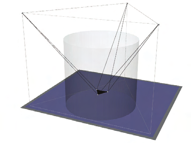
waste remediation, aircraft paint stripping, and shipbuilding. Figure 1 depicts the
RoboCrane TETRA configuration (a) and the representative work volume (b). Figure 2
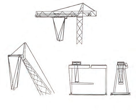
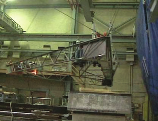
shows additional retrofit configurations of the RoboCrane platform, and Figure 3 shows
implementations for shipbuilding (Bostelman et al., 2002) and aircraft maintenance.
(a) (b)
Fig. 1. RoboCrane – TETRA configuration (a); Rendering of the RoboCrane environment.
The shaded cylinder represents the nominal work volume (b).
Fig. 2. Illustrations of RoboCrane in possible retrofitted configurations: Tower Crane (top),
Boom Crane (lower left) and Gantry Bridge Crane (lower right).
1.2 Motivation for current research
Productivity gains in the U.S. construction sector have not kept pace with other industrial
sectors such as manufacturing and transportation. These other industries have realized their
productivity advances primarily through the integration of information, communication,
Control of Cable Robots for Construction Applications
3
automation, and sensing technologies. The U.S. construction industry lags these other
sectors in developing and adopting these critical, productivity-enhancing technologies.
Leading industry groups, such as the Construction Industry Institute (CII), Construction
Users Roundtable (CURT) and FIATECH, have identified the critical need for fully
integrating and automating construction processes.
Robust field-automation on dynamic and cluttered construction sites will require advanced
capabilities in construction equipment automation, site metrology, 3D imaging, construction
object identification and tracking, data exchange, site status visualization, and design data
integration for autonomous system behavior planning. The NIST Construction Metrology
and Automation Group (CMAG) is conducting research to provide standards,
methodologies, and performance metrics that will assist the development, integration, and
evaluation of these technologies. Of particular interest are new technologies and capabilities
for automated placement of construction components.
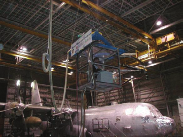
(a) (b)
Fig. 3. The NIST Flying Carpet – a platform for ship access in drydocks (a) and the NIST
Aircraft Maintenance Project (AMP) – a platform for aircraft access in hangars (b).
2. RoboCrane kinematics
From (Albus et al., 1992), given an initial condition where the overhead support and the
suspended platforms are represented by parallel, equilateral triangles with centers aligned
along the vertical axis Z, (see Figure 4), the positions of the upper triangle with vertices A, B,
and C and lower triangle with vertices D, E, and F are expressed as
⎡
b
−
⎤
⎡
b
⎤
⎡ 0 ⎤
⎢ 1
⎥
⎢ 1
⎥
⎢2
⎥
A = ⎢− b 3⎥ B = ⎢− b 3⎥ C = ⎢ b 3⎥
⎢ 3
⎥
⎢ 3
⎥
⎢3
⎥
⎢
h ⎥
⎢
h ⎥
⎢
h ⎥
−
−
−
⎣
⎦
⎣
⎦
⎣
⎦
(1)
⎡
0
⎤
⎡ a ⎤
⎡ − a ⎤
⎢ 2
⎥
⎢1
⎥
⎢1
⎥
D = ⎢− a 3⎥
E = ⎢ a 3⎥
F = ⎢ a 3⎥
⎢ 3
⎥
⎢3
⎥
⎢3
⎥
⎢
0
⎥
⎢ 0 ⎥
⎢ 0 ⎥
⎣
⎦
⎣
⎦
⎣
⎦
4
Parallel Manipulators, Towards New Applications
With the positions of the vertices of triangles ABC and DEF as described in equations (1),
when the lower platform is moved to a new position and orientation (DÉ´F´) through a
translation of
⎡ u ⎤
x
⎢
U
u ⎥
=
(2)
y
⎢ ⎥
⎢ u ⎥
⎣ z ⎦
and a rotation of
R (γ ,θ ,φ) = R (φ) ⋅ R (θ ) ⋅ R (γ ) (3)
yxz
z
x
y
the cable lengths can be expressed as
⎡
2
⎤
⎡
2
⎤
b
− + aQ
3 − u
− b + aQ
3 − u
⎢
12
x
⎥
⎢
12
3
3
x
⎥
⎢
⎥
⎢
⎥
⎢ 1
2
⎥
⎢ 1
2
L
b 3
aQ
3 u
L
b 3
aQ
3 u ⎥
= −
+
−
= −
+
−
1
22
y
2
22
⎢ 3
3
⎥
⎢ 3
3
y ⎥
⎢
⎥
⎢
⎥
2
2
⎢
h
aQ
3 u
⎥
⎢
h
aQ
3 u
⎥
− +
−
− +
−
32
z
32
⎢
3
⎥
⎢
3
z
⎥
⎣
⎦
⎣
⎦
⎡
1
⎤
⎡
1
⎤
b − aQ − aQ
3 − u
⎢
− aQ − aQ
3 − u
11
12
3
x
⎥
⎢
11
12
x
⎥
⎢
⎥
3
⎢
⎥
⎢ 1
1
⎢ 2
1
L
b 3 aQ
aQ
3 u ⎥
= −
−
−
−
L
b 3 aQ
aQ
3 u ⎥
=
−
−
−
(4)
3
21
22
⎢ 3
3
y ⎥
4
21
22
y
⎢
⎥
⎢
3
3
⎥
⎢
⎥
1
⎢ −
1
h − aQ − aQ
3 − u
⎥
⎢
h aQ
aQ
3 u
⎥
− −
−
−
31
32
⎢⎣
3
z
⎦
31
32
⎥
⎢
3
z
⎥
⎣
⎦
⎡
1
⎤
⎡
1
⎤
aQ − aQ
3 − u
− b + aQ − aQ
3 − u
⎢
11
12
x
⎥
⎢
11
12
3
3
x
⎥
⎢
⎥
⎢
⎥
⎢ 2
1
⎥
⎢ 1
1
L =
b 3 + aQ − aQ
3 − u
L = − b 3 + aQ − aQ
3 − u ⎥
5
21
22
y
6
21
22
⎢ 3
3
⎥
⎢ 3
3
y ⎥
⎢
⎥
⎢
⎥
1
⎢
1
h aQ
aQ
3 u
⎥
− +
−
−
⎢ − h + aQ
aQ
3 u
⎥
−
−
31
32
z
3
⎢
3
⎥
⎣
⎦
1
32
⎢
3
z
⎥
⎣
⎦
where
L = A - ′
D
L = B - ′
D
L = B - ′
E
1
2
3
(5)
L = C - ′
E
L = C - F′ L = A - F′
4
5
6
and Q represents an element in the following rotation matrix:
ij
⎡cos(γ )cos(φ) − sin(γ )sin(θ )sin(φ) −cos(θ )sin(φ) sin(γ )cos(φ) + cos(γ )sin(θ )sin(φ)⎤
⎢
Q
cos(γ )sin(φ) sin(γ )sin(θ )cos(φ)
cos(θ )cos(φ)
sin(γ )sin(φ) cos(γ )sin(θ )cos(φ)⎥
=
−
−
⎢
⎥ (6)
⎢
−sin(γ )cos(θ )
sin(θ )
cos(γ )cos(θ )
⎥
⎣
⎦
Therefore, for any new desired pose of the moving platform described by equations (2) and
(3), the required cable lengths to achieve that pose can be calculated by the inverse
kinematic equations shown in equations (4).

Control of Cable Robots for Construction Applications
5
Fig. 4. Graphical representation of the RoboCrane cable support structure.