The Millennium Time Project: Alternative Time Measuring Mechanisms by Miltiadis A. Boboulos - HTML preview
Download the book in PDF, ePub, Kindle for a complete version.
13.2. Device operation principle
Hot air becomes lighter when heated and moves up. The hot air flowing through a pipe forms an airflow moving up from the heat source. This flow is used to drive a sensitive screw (an air screw having many blades), which moves a transmission to a clock mechanism with an aerodynamic stroke controller [14].
13.2.1. ArrangementA slowly rotating air screw 2 is mounted in the upper section of a conicalshaped lampshade (for example, a movable lamp 1). A gear Z1 is installed on the axle of the screw 2 and it drives and gear transmission to a reducer Z1/Z2. An eccentric finger 10 is installed on the gear Z2 to move the ratchet clutch 12 (arm), which is engaged with the ratchet gear 11. The 12 winds a friction clock spring provided in the drum 13 with the gear Z3. The transmission from there is Z3/Z4, Z5/Z6. The gear Z6 – item 9 has an aerodynamic controller 7 installed on its axle. The gear Z5 has an eccentrically positioned finger 6 engaged with a saw-tooth gear having internally positioned teeth and positioned on a hollow cylindrical vernier – scale 4.This scale is loosely seated by means of the stands 8 on the axle of the gear 9 and supported by means of radial bonding 8.
13.2.2. OperationWhen the hot air heated by the electrical lamp flows through the vanes of the screw 2 it rotates and winds the spring in the drum13 via the transmission Z1/Z2 and the ratchet clutch 12. The spring in the drum 13 in turn rotates the indicating drum with the scale 4 by means of the gear transmission Z3/Z4, Z5/item 5. The reading is performed using the hand 3 fixed to the lampshade. The gear 9 is also rotated faster than Z5 by means of the Z5/Z6 transmission and 9 also rotates the strips of the air regulator 7.
Miltiadis Boboulos, Ph.D. Page 37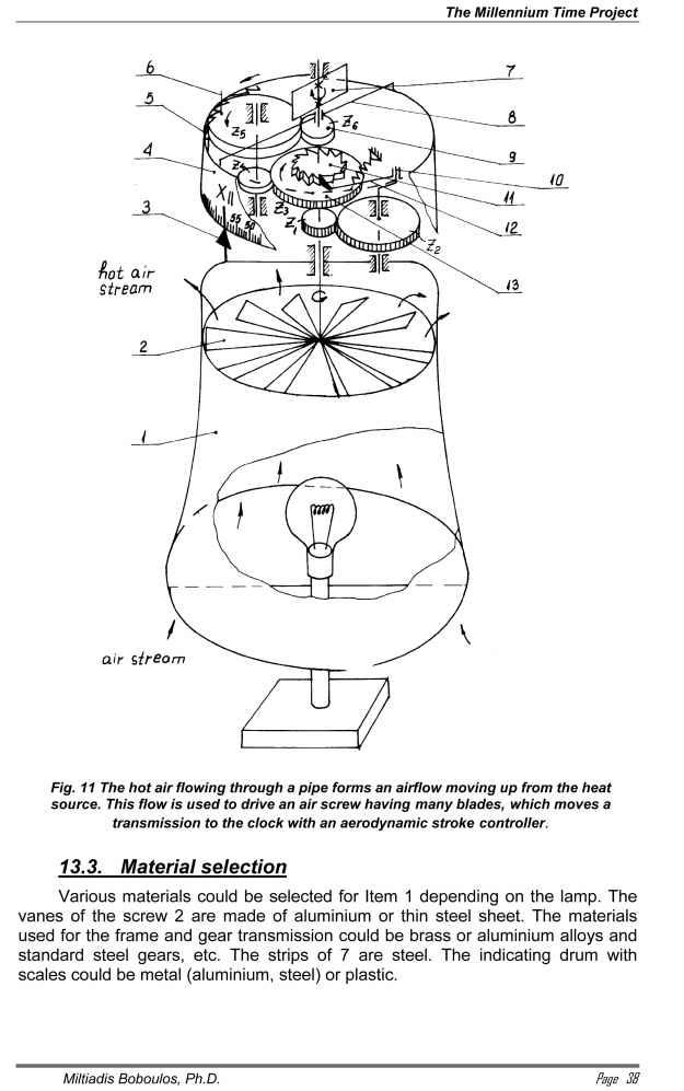
 14.2.2. Operation
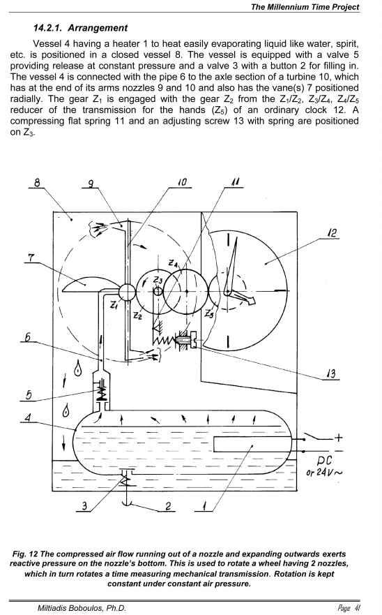
When 1 heats the liquid in 4 it evaporates and once a certain pressure is reached the air flows out of the valve 5 along the pipes 6 and 10 towards the reactive nozzles 9 expanding and flowing out of them. As a result of the reactive force occurring the rotor – turbine wheel 10 rotates and moves the gear transmission of the reducer along with the indicating hands. The condensing liquid returns back to a tank under the vessel 4. The rotation speed of 10 and, hence the accuracy of reading are adjusted by rotating the vanes 7 around their axis (radial direction) changing the aerodynamic resistance and by controlling the friction of 11 on Z3 by means of the screw 13. When the liquid in 4 is exhausted the tank 4 can be refilled by pressing the button 2.