Microsensors by Igor V. Minin and Oleg V. Minin - HTML preview
Download the book in PDF, ePub, Kindle for a complete version.
E 2
0.409
E
1.0
MGT3 with W L
and LG W
E 2
0.212
E
02
Magnetic Microsensors
13
It is noticed that the NEMI is minimum for W L
, and for smaller values of this ratio.
E
0.5
The decreasing of the channel length causes the increase of NEMI with 40.8 % for a square
structure W L and with 173 % for W 2 L .
E
Conclusions
The magnetotransistors have a lower magnetic sensitivity than the conventional Hall
devices but allow very large signal-to-noise ratios, resulting in a high magnetic induction
resolution. The analysis of the characteristics of two magnetotreansistors structures shows
that the W L 0.5 ratio is theoretically favourable to high performance regarding signal-to-
noise ratio, as well as the noise equivalent magnetic induction
Also substituting the silicon technology by using other materials such as GaAs or InSb with
high carriers mobility values assure higher characteristics of the sensors
The uses of magnetotransistors as magnetic sensors allows for the achieving of some
current-voltage conversion circuits, more efficient that conventional circuits with Hall
plates.
The transducers with integrated microsensors have a high efficiency and the possibilities of
using them ca be extended to some measuring systems of thickness, short distance
movement, level, pressure, linear and revolution speeds.
1.7 System to monitor rolling and pitching angles
The efficient operation of the modern maritime ships requires the existence of some reliable
command, watch and protection systems that permit transmission, processing and
receiving of signals with great speed and reduced errors.
On most of the merchant ships the watch of the rolling and the pitching is done by
conventional instruments as gravitational pendulum. The indication of the specific
parameters is continuous, the adjustment operations are manual and the transmissions of
the information obtained in the measurement process, at distance is not possible.
An automatic and efficient surveillance system ensures the permanent indication of the
inclination degree of the ship , the optic and the sound warning in case of exceeding the
maximum admissible angle and the simple transmission of the information at distance.
1.7.1 Installation for the measurement of the rolling and pitching thatuses
magnetotransistors
The presentation of the transducers
The primary piece of information about the rolling and pitching angle is obtained with the
help of the classical system used on ships, with the difference that at the free end of the
pendulum,a permanent magnet with reduced dimensions is fixed provided with polar parts
shaped like those used in the construction of the magnetoelectric measurement devices. Along
the circle arc described by the free end of the pendulum , there are disposed at equal lengths,
accordingly to the displacements of 1 for the rolling and of 1 30’ for the pitching, twenty
magnetotransistors, ten on one side and ten on the other side of the equilibrium position.
Due to the high inertia moment, the pendulum maintains its vertical position, and actually
during the rolling and pitching the graded scale, fixed on the wall, is the one that moves at
the same time with the ship.
14
Microsensors
The transducer for the indication of the rolling is disposed in a vertical plane, transverse on
the longitudinal axis of the ship, and the one for the pitching in a vertical plane that contains
or is parallel with the longitudinal axis of the ship. In order to simplify the presentation will
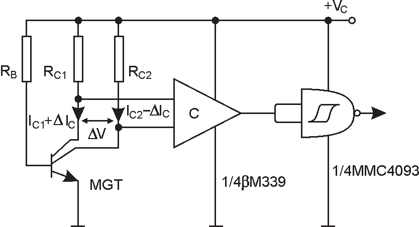
consider that the pendulum is the one that moves in with the graded scale. In figure 1.14 the
principle diagram of the transducer is shown vertical bipolar magnetotransistor with double
collector. In the absence of the magnetic field, the two collector currents are equal and the
output of the comparator is in “DOWN” state (logical level ,,0”). In the presence of a field
of induction B, parallel with the device surface, a lack of poise between the two collector
currents I is produced and at the input of comparator is applied the voltage:
C
V
L W GR I B (1.18)
C
H
/ E
C C
Fig. 1.14. The electric diagram of transducer
This voltage is applied to a comparator with hysteresis, which acts as a commutator. The
existence of the two travel thresholds ensure the immunity of the circuit at noise monostable
made with MMC 4093 ensures the same duration for the transducers generated pulses.
Applied to the comparator C, this voltage changes its state and the output goes on logical
level “1”.
The principle block diagram. The description of working
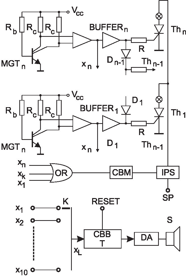
When the ship lists, the permanent magnet of the pendulum will scavenge in turn a number
of magnetotransistors, and the signals from their outputs will determine the tipping of the
comparators. We will thus obtain impulses which are applied through an “OR” circuit at
the CBM input (figure 1.15). This commands the block for the interruption of the power
supply (IPS), achieving the cancellation of the potentials in the thyristors anode for a time
interval of milliseconds.
At the same time the impulses generated by the transducers are transmitted with the help of
separator B1, B2, …, B10 on the thyristors gates, determining their damping. Once the
thyristors are damped, they maintain that state, therefore these are memorizing the last
indicated value, until the power supply is cancelled. So if the rolling or the pitching have
intermediate values ranging between the successive marks of the graded scale , the last
complete measured value remains displayed.
Magnetic Microsensors
15
For a rolling value noted with “K” , all the displays from one to “K” will work in “bright
point” mode, when for the same “K” value of the rolling will be lighted, therefore the
scheme allows the analogical display in bar mode.
Eliminating the diodes D1, D2, …, D9, the display will be in ”bright spot” mode when for
the same value “K” of rolling only the “K” display is lighted.
If the inclination of the ship reaches a limit value L settled beforehand with the help of the
,,K” switch , then the output signal XL (L=1,2,…,10) commands the bistable of T type which
commutes, releasing the sound alarm device.
Fig. 1.15. The diagram of the installation for the measurement of the rolling and pitching
Supposing that the angle of the ship’s list increases, the pendulum overtakes the ,,L’’
position and after it touches a maximum deviation it starts the return run in which it will
pass again through the front of the magneto transistor. The impulse generated by this, will
swing again the bistable and the sound alarm ceases.
An undesirable situation appears when the maximum inclination of the ship has precisely
the pre-established “L” value or it exceeds very little this value. In this case, in the return
16
Microsensors
run of the pendulum a new “XL” impulse, which will swing again the bistable, is no longer
generated and therefore the acoustic alarm is maintained although the inclination angle has
been reduced.
This drawback can be eliminated either by using the “XL-1” output for the bistable command
on the input or by replacing the bistable with one of R-S or J-K type commanded by “XL”
and “XL-1” signals. The “XL” signal establishes the placing in function of the alarming device
and the XL-1” signal the blockage of this device, which permits to obtain a safety hysteresis.
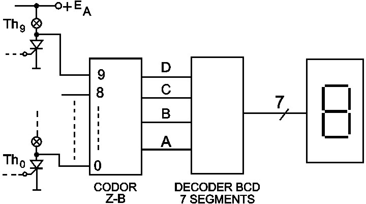
If in the scheme in figure 1.15 the diodes D1, D2, …, D9 are eliminated, then in every
moment a single thyristor will be in conduction, suitable at a certain angle.
The signals in the anodes of the other blocked thyristors will be at the logical level “1” and
only in the anode of the commanded thyristor the signal will have the logical level “0”. This
signals are applied to a binary-decimal circuit, at the output of which is obtained the value
of the angle in the binary code. A decoder seven segments which commands a display with
seven segments and permits the digital display of the measured value.(figure 1.16).
The binary-decimal coder can be a matrix of diodes, a matrix of connected gates in a suitable
way, or a specialized circuit like those used in numerical keyboards.
Fig. 1.16. The electrical diagram of the digital display
1.7.2 Installation for the measurement of the rolling and the pitching that uses
phototransistors
The presentation of the transducer
The principle scheme of the photoelectric transducer is shown in figure 1.17. Classical
system on board ships,is used but at the free end of the gravitational pendulum an
electroluminiscent diode (LED) in visible or in infrared is set moves along an arc of circle on
which the phototransistors are placed. The LED pendulum and the phototransistors are
fixed in a box which protects them from the exterior light.
The power supply is ensured from a stabilized source of 12V.
Through one phototransistor, with off–load base / unconnected base and in the absence of
the light the so-called “dark current” will flow between the emitter and the collector.
I I
(1.19)
D
CB 0
where denotes the amplification factor of the transistor and I
is the current generated
CB 0
by the base-collector junction, in the absence of light.
Magnetic Microsensors
17
When the base-collector junction is illuminated, through this an illumination current will
appear ( I and this current is all the intense as the illumination is bigger, and the collector l )
current becomes:
I I
I
(1.20)
C
CB 0 l
Since the phototransistors are blocked in the absence of the illumination, the output voltage
of the collector is practically equal with the value of the power supply ( E) . In the moment
of the illumination the phototransistors are saturated and the collector voltage lowers to
U
value. Therefore the signal given by the transducer is in shape of negative power
CEsat
impulses with the amplitude approximately equal to the value of the power supply
+ED=12V
R
R
D
C
I
I
D
C
LED
Q0
Fig. 1.17. The photoelectric transducer
The principle block diagram. The description of working
Because the measurement of the rolling and the pitching is in fact reduced to the
measurement of an angle, the measurement system is made up of two identical
measurement blocks, one for the rolling and the other for the pitching, with the difference
that the measurement transducer will be placed differently: the one for the rolling on the
transversal axis of the ship and the one for the pitching on the longitudinal ship’s axis.
In figure 1.18 it is presented the block scheme of the measurement system of the inclination
angle of the ship on the longitudinal (transversal) axis of the ship. In this scheme the
following notations have been used: TM -measurement transducer of the rolling (pitching);
CF - formatter circuit; CM-memory cell; IO - optic indicator; CR -resetting circuit; OC -
commanded oscillator; AAF – audio frequency amplifier; SB - supply block; HA - warning
block.
It is noticed that the measurement system is made up “2n+1” identical measurement and
display chains:
-
a chain corresponding to the equilibrium position (zero)
-
“n” chains corresponding to ,,n” number of values of the port inclination angle (stern)
-
“n” chains corresponding to ,,n” number of values of the starboard inclination angle
(bow)
The measurement transducer (TM) supplies the necessary information about the inclination
angle in a discrete way, meaning that the total angle can be measured has been divided into
“2n” sectors (“n” port sectors “n” starboard sectors), and the transducer supplies one
impulse for the output suitable for the inclination angle reached by the ship. The impulse
18
Microsensors
suitable for this angle is processed in the formatter circuit (CF) and it is applied to the
corresponding memory cell (MC), in which the information about the inclination angle of
the ship is kept. This information is displayed by the optic indicator (IO) corresponding the
same sector, until the ship, in her movement, reaches the same inclination angle, but moving
in reverse direction. The measurement transducer generates at the same output a new
impulse that wipes up the information from the memory cell and at the same time the
display of the optic indicator. In this way, the measurement transducer supplies two
impulses for every inclination angle of the ship, except for the maximum inclination angle,
which is pre-established. In case of maximum inclination, the transducer produces a single
impulse that is memorized and displayed until the ship, after she reaches the maximum
inclination angle in the opposite direction, returns to the equilibrium position. In the passing
moment through the equilibrium position, the impulse from the CF out put wipes up, with
the help of a reset circuit (CR), the information from all the memory cells and therefore from
the cells corresponding to the maximum angles for the two inclination ways of the ship.
From now on the working of the system is continued from the equilibrium position.
CF
CM
IO
2n
2n
2n
n
CF
CM
IO
21
21
21
2
1 K
OC
AAF
TM
CF
CM
IO
0
0
0
CF
CM
IO
11
11
11
CF
CM
IO
12V
1n
1n
1n
BA
220V, 50Hz
16V
CR
Fig. 1.18. The block diagram of the measurement system based on the phototransistors
Conclusions
The use of another transducer type for the measurement of the rolling and the pitching,
namely the classic solution with the transducers in Gray code, would have reduced the
number of the components. With such a transducer, using eight pairs of LED
phototransistors a measurement accuracy of the angle, better with 1, could have been
obtained. Besides, this system allows the long distance transmission of the information, but
the solution would have required a sophisticated electronic part, the major difficulty being
the precise construction achievement of the Gray transducer in eight bits.
The block scheme also contains a sound warning system, which is triggered at a maximum
inclination angle pre-established with the help of “K” switch. Once this switch fixed on the
desired position, the logical level from the output of the memory cell corresponding to the
chosen angle, it will command and release the sound warning system.
Magnetic Microsensors
19
This is made up of a command oscillator (OC), an audio frequency amplifier (AAF) and a
warning horn (HA). The command signal of the sound warning system is taken over from
the input of the optic indicator and not from its output, although it would have been easier
to achieve this, out of safety operation reasons. The probability of the memory cell to go out
of order is less than that of the optical indicator, moreover, if the optical indicator goes out
of order that doesn’t imply that the sound warning system gets inoperative.
2. Introduction
The possibility of modelling the channel depth by means of the external supply voltage and
low value of area carrier density suggests the possibility of using the MOSFET channel as
the active region of a Hall plate.
At the same time, the advantage of integrating on the same chip of a magnetic sensor and
the signal processing circuit is outlined.
The Hall devices in MOS structure have some drawbacks: the carrier mobility in the channel
is half of its value in the volume of the device; the increasing of 1/f noise, and the instability of device surface.
The analysis made in this paper outlines the way in which the way of choosing the adequate
choice device material and dimensions allows the improvement of CMOS technology sensors.
The double-drain magnetotransistor
2.1 The characterisation of the double-drain magnetotransistor
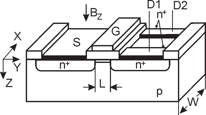
The double – drain MOS device (figure 2.1) is obtained from a MOSFET structure where its
conventional drain region is replaced by two adjacent drain regions[7]. Consequently, the
total channel current is shared between these two drain regions.
Fig. 2.1. Double-drain MOSFET magnetotransistor
The result of the bias is the linear region is the obtained of a continuous channel of
approximately constant thickness, which can be assimilated with a Hall plate.
The deflection of current lines appears under the action of a magnetic field B, perpendicular
to the device surface. The carrier deflection causes a discrepancy between two drain currents:
20
Microsensors
I I ( B) I (0) I ( B) I
(2.1)
D
D
D
D
D (0)
1
1
2
2
Since the output signal of the double-drain MOS magnetotransistors consists of the current
variation between its terminals, this device operates in the Hall current mode. Using the
features of dual Hall devices, and the Hall current expression it results [2]:
I
L
H
1
I
G I B
(2.2)
D
2
2 H
D
Ch W
The supply-current-related sensitivity of the devices is defined by:
1
I
L
D
1
S
G
(2.3)
I
I
B
2 HCh W
D
where G denotes the geometrical correction factor and
is the Hall mobility of the
HCh
carriers in the channel.
For a given induction B 0,4 T and at given drain current I mA , the sensitivity D
1
depends of the device geometry and the material properties.
In table 2.1 the values for five magnetotransistors structures are presented.
Device
W L
2
sm
S [ 1
T ]
C
H
I
MGT1 2 0,07
Si
0,018
MGT2 1 0,07
Si
0,025
MGT3 0,5 0,07
Si
0,028
MGT4 0,5 0,23
InP
0,084
MGT5 0,5 0,42
GaAs
0,146
Table 2.1. The numerical values of the supply-current sensitivity
2.2 The sensor response
The sensor response is expressed by:
I
L