TOW Weapon System by Department of the Army - HTML preview
Download the book in PDF, ePub, Kindle for a complete version.
INTRODUCTION
The TOW is a crew-portable heavy antitank missile weapon system that can be operated from armored, lightly armored, and unarmored multipurpose vehicles and helicopters, and from the ground mount. The system consists of a guided missile and a launcher to engage tanks, fortifications, and other materiel targets. The term “TOW” is an acronym derived from the words that describe the principal operating features of the missile⎯ tube-launched, optically tracked, wire-guided. The launcher initiates, tracks, and controls the flight of the missile by guidance signals transmitted over a command-link wire that connects the missile with the launcher.
1-1. CHARACTERISTICS
The TOW weapon system consists of a launcher, which has tracking and control capabilities, and the missile, which is encased in a launch container. The launcher is equipped with self-contained, replaceable units.
a.
Capabilities. The TOW is mainly an antitank weapon used for long-range engagement of armored targets. It can be employed in all weather conditions as long as the gunner can see his target through the daysight tracker or nightsight. The TOW also provides a long-range assault capability against heavily fortified bunkers, pill boxes, and gun emplacements.
(1) The ITOW missile can destroy targets at a minimum range of 65 meters and a maximum range of 3,750 meters. The TOW 2B missile can destroy targets at a minimum range of 288 meters when fired from the ground mount and 200 meters when fired from the HMMWV or BFV. The TOW 2B has a maximum range of 3,750 meters whether ground- or vehicle-mounted.
(2) The automatic missile tracking and control capabilities of the TOW weapon system provide a high first-round-hit probability. To operate the system, the gunner places the crosshairs of the sighting system (either the daysight tracker or the nightsight) on the target, fires the missile, and centers the crosshairs on the target image until missile impact. The optical tracking and command functions within the system guide the missile along the gunner’s line of sight. The gunner does not apply lead, windage, or elevation.
b.
Mobility. The TOW weapon system can be vehicle-mounted or ground emplaced (tripod-mounted) for operation. Missiles can be launched from either operational mode.
(Detailed operating procedures for each configuration are provided in Chapters 2 and 3.) (1) The entire system can be hand-carried by a weapon crew; therefore, emplacement sites can be changed quickly to minimize detection or to engage targets that are out of range.
(2) The vehicle-mounted launcher is more mobile and can be quickly prepared for use. The launcher can be assembled and disassembled without the use of tools.
(3) Built-in self-test circuits can be used to check the operational condition of the assembled launcher whether ground- or vehicle-mounted.
1-1
FM 3-22.34
1-2. SYSTEM
CONFIGURATIONS
The TOW weapon system comes in two configurations⎯the M220A1 (TOW) and the M220A2 (TOW 2).
a.
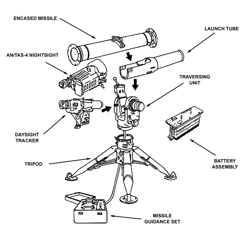
M220A1 TOW Weapon System. The M220A1 TOW (Figure 1-1) consists of a tripod, a traversing unit, a launch tube, a daysight tracker, an AN/TAS-4 nightsight, a missile guidance set (MGS), a battery assembly housed in the compartment of the MGS, and an encased missile.
(1) The M220A1 TOW weighs about 265.5 pounds with all of its components and carrying cases; with encased missile (BGM-71A), it weighs 320 pounds. (For a detailed description of the M220A1 TOW, see TM 9-1425-472-12.)
(2) The M220A1 TOW can fire all four configurations of TOW missiles, which include many types. However, it cannot take full advantage of the BGM-71D TOW 2 and BGM-71E TOW 2A or TOW 2B counter countermeasures when tracking through obscurants.
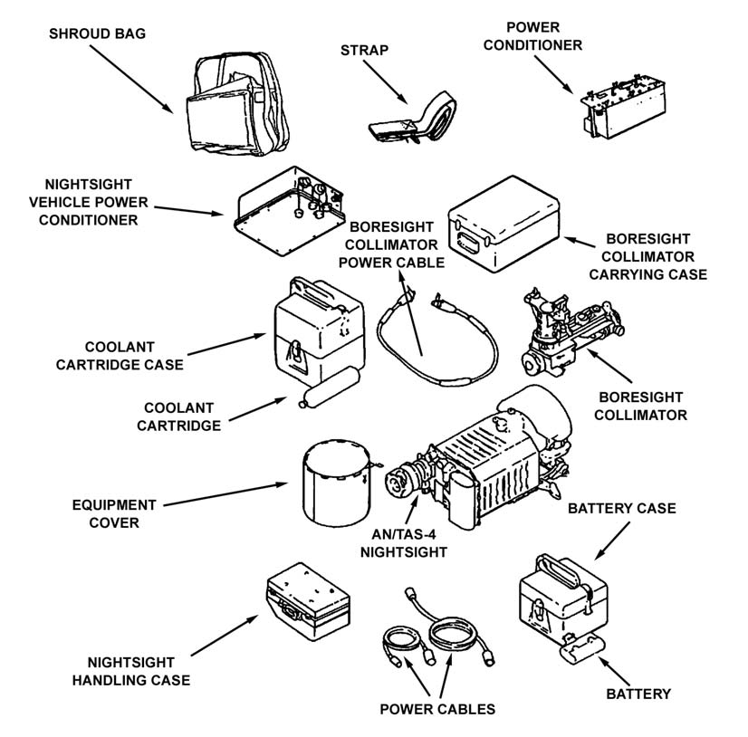
Figure 1-1. M220A1 TOW components.
1-2
FM 3-22.34
Figure 1-1. M220A1 TOW components (continued).
b.
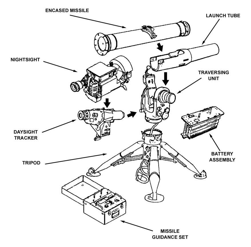
M220A2 TOW 2 Weapon System. The M220A2 TOW 2 (Figure 1-2, page 1-4) is a combination of a modification to the M220A1 TOW launcher and the addition of a new missile. The traversing unit, the digital MGS, and the AN/TAS-4A thermal nightsight of the M220A1 TOW launcher were modified to form the M220A2 TOW 2
launcher. (For a detailed description of the M220A2 TOW 2, see TM 9-1425-450-12.) (1) The M220A2 TOW 2 weapon system weighs about 256.5 pounds with all of its components and carrying cases; with encased missile BGM-71D, it weighs about 318.5
pounds.
(2) The TOW 2 missile (BGM-71D) improvements include a new guidance link, a full-caliber 6-inch warhead, a reloaded flight motor, and a longer warhead probe.
(3) The M220A2 TOW 2 launcher is compatible with all four missile configurations.
It can achieve a higher probability of hit against all types of targets through improved microprocessor-based electronics that use digital design techniques.
1-3
FM 3-22.34
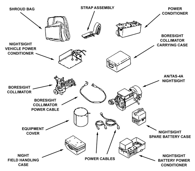
Figure 1-2. M220A2 TOW components.
1-4
FM 3-22.34
Figure 1-2. M220A2 TOW components (continued).
1-3.
MISSILE CONFIGURATIONS AND TYPES
The TOW missile comes in four configurations with numerous types. These types mainly consist of minor modified work orders (MWOs) that are transparent to the operator and are continually added to. This FM will not attempt to deal with the various types but will confine itself to the four major configurations. All configurations use the same basic airframe, aerodynamic control system, command-link wire, and missile electronics designs.
a. The first configuration is the improved TOW (ITOW). These missiles have improved 5-inch warheads that include extended probes for greater standoff and penetration.
b. The second configuration is the TOW 2. This missile has a full-caliber 6-inch warhead that includes an extended probe. In addition to the infrared radiator of the ITOW
missile, TOW 2 has a second infrared radiator to provide hardened system performance against battlefield obscurants and countermeasures. The second radiator is called the thermal beacon and provides link compatibility with the electrooptical infrared nightsight, which is part of the TOW 2 launcher system.
1-5
FM 3-22.34
c. The third configuration is the TOW 2A. The TOW 2A has an added small explosive charge in the tip of the extended probe providing improved performance against reactive armor by premature detonation.
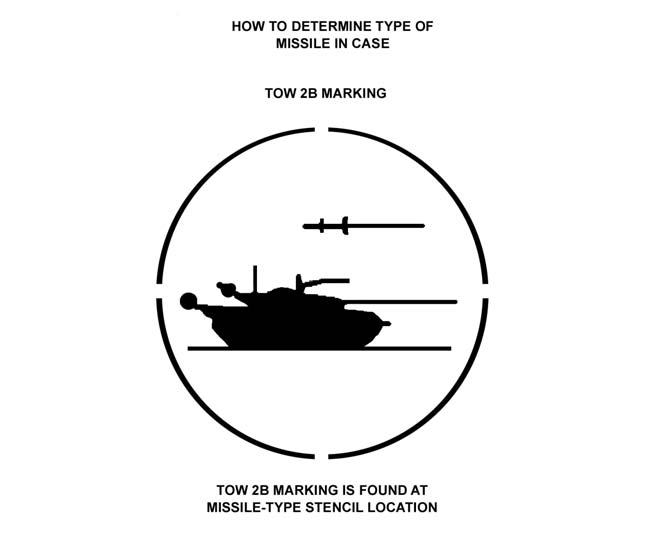
d. The fourth configuration is the TOW 2B. The TOW 2B has an entirely different warhead and kill mechanism than the other TOW missiles. It is a top-attack missile (fly over/shoot down [FOSD]) that defeats enemy armor at its most vulnerable point⎯the top deck of the turret and hull. The TOW 2B has a tandem warhead that fires two explosively formed projectiles (EFPs) down through the thin upper deck armor of the enemy vehicle.
The gunner tracks the target the same as any other TOW missile with the crosshairs on center mass, but the missile automatically flies 2.25 meters above the line of sight (LOS).
When the missile senses that it is directly above the target (by means of the target’s shape and magnetic field), it automatically fires its warhead.
1-4.
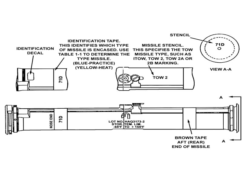
TOW MISSILE IDENTIFICATION
With the increased number of TOW missile types and wide variations in their capabilities (especially armor penetration), TOW crews and range safeties must be able to quickly and accurately identify the specific type of missile they have.
a. The configuration of the missile can be readily identified by the various identification decals, tapes, and stencils on the missile case (Figure 1-3 and Table 1-1).
(See TM 9-1410-470-34 for current information on TOW missiles.)
Figure 1-3. TOW missile case markings.
1-6
FM 3-22.34
TYPE OF MISSILE
DECAL PLATE DATA
Improved TOW Practice
Guided Missile Practice, STD, BTM-71A1
Improved TOW HE
Guided Missile Surface Attack,
ITOW-BGM-71C
TOW 2 Practice
Guided Missile Practice, TOW 2,
BTM-71D-1B
TOW 2 HE
Guided Missile Surface Attack, TOW 2,
BGM-71D-3B
TOW 2A Practice
Guided Missile Practice, TOW 2A,
BGM-71E-3B
TOW 2B Practice
Guided Missile Practice, TOW 2B,
BTM-71E-2B
TOW 2B HE
Guided Missile Surface Attack, TOW 2B,
BGM-71F
Decals are located on the nose end of the launcher tube. They describe the type of round and model.
BLUE—indicates
practice
round.
YELLOW—indicates HE round.
WHITE—indicates HE or practice round.
BROWN—indicates low explosive (live rocket motor).
Table 1-1. TOW missile identification.
b. The TOW 2B missile is unique because it is an FOSD missile. It is marked with a decal as shown in Figure 1-4.
Figure 1-4. TOW 2B marking.
1-7
FM 3-22.34
1-5.
INTERNAL COMPONENTS AND SEQUENCE OF OPERATIONS
A TOW crewman or leader who thoroughly understands his weapon will be able to employ it to its maximum effectiveness. This paragraph describes the internal missile operations from trigger depression to missile impact, which will increase the soldier’s knowledge of how his weapon functions.
a.
Major Internal Sections and Components. The missile is divided into three major sections and the launch container.
(1)
Front Section. The front section contains the warhead and the electronics.
(a) The warhead contains an extended probe on the ITOW and TOW 2-series (17
inches on TOW 2, 10 inches on ITOW). All missile types have a crush ogive switch to detonate the missile (located in the end of the probe tip on ITOW and TOW 2). The warhead is a conventional shaped charge (except TOW 2B) with a copper cone and liner and a detonator at the rear of the charge. The diameter of the warhead is 5.2 inches on ITOW and 6 inches on TOW 2 and 2A.
(b) All electronic circuitry necessary to perform on-board electronic functions while the missile is in flight is contained in the front section. This circuitry receives steering signals from the MGS and corrects the missile flight path to conform to LOS.
(2)
Center Section. The center section contains the thermal batteries, the gyroscope, the flight motor, and wings.
(a) The missile has three thermal batteries, which are used instead of storage batteries because their shelf life is much longer. The chemical reaction that produces both heat and electricity is started by an electrical charge that is part of the prefire signal sent when the trigger is depressed. Within approximately two tenths of a second the batteries begin producing electricity.
(b) The gyroscope stabilizes the missile in flight, and it provides information about the attitude of the missile to the MGS from sensors in its housing. When the prefire signal is sent to the missile, an explosive squib on the neck of a bottle of compressed nitrogen is ignited. This produces the popping sound and whirring noise that is heard after the gunner depresses the trigger and before the missile launches. The escaping nitrogen causes the gyroscope to begin spinning in its bracket. When the gyroscope reaches 42,000 rpm, it automatically disengages from its bracket and begins to spin freely in its housing. This causes an electrical current that ignites the launch motor launching the missile from the weapon system.
NOTE:
The process of the thermal batteries heating up to produce electricity and the gyroscope coming up to speed and igniting the launch motor takes about 1.5
seconds. This causes the delay between the time when the gunner presses the trigger and the missile actually fires.
(c) The flight motor is a solid fuel rocket motor with two nozzles protruding through the body of the missile at 30-degree angles. The flight motor burns for 1.6 seconds.
During this time, it provides all the momentum necessary for the full flight of the missile.
(d) For the rest of its flight, the missile coasts on momentum and the lift provided by the four wings. The wings are located just aft of the flight motor, recessed into the body of the missile during storage and spring loaded. When the missile leaves the launch 1-8
FM 3-22.34
container, the wings open and lock into place. The wings are set at 45-degree angles to the body of the missile.
(3)
Aft Section. The aft section contains the wire spools, the launch motor, the actuator control system and control surface push rods, a bottle of compressed helium, the flight control surfaces, the xenon beacon (on all missiles), and the thermal beacon (on TOW 2-series missiles only).
(a)
Wire Spools. Two wire spools, each holding 3,750 meters of wire, are located at the rear of the missile. The wire is made of fine steel and is coated with a thin layer of varnish for insulation. There is virtually no tension on the wire, so it droops down on the ground behind the missile as the missile flies downrange.
(b)
Launch Motor. The launch motor is a solid fuel rocket that burns entirely inside the launch tube. It provides just enough thrust to propel the missile to a point where the flight motor can ignite safely without injuring the gunner.
(c)
Flight Control Surfaces. Four flight control surfaces are located on the aft end of the TOW missile set at 90-degree angles to the body of the missile. The TOW, unlike the Dragon, does not spin in flight but maintains a stable position. One pair of flight control surfaces controls the “up and down” (pitch) corrections while the other pair controls the
“left and right” (yaw) corrections. Like the wings, the flight control surfaces are recessed into the body of the missile while in the launch container. They spring out and lock into place when the missile leaves the launch container.
(d)
Actuator Control System/Push Rods/Helium Bottle. The TOW missile makes steering corrections by moving the flight control surfaces. It moves them by opening and closing the valve on a bottle of compressed helium. The escaping helium moves a system of push rods back and forth. The push rods are connected to the flight control surfaces and move them in turn. The valve on the helium bottle opens and closes in response to signals sent by the on-board electronics, which are responding to signals sent down the wires by the MGS.
(e)
Xenon Beacon. The xenon beacon emits an infrared beacon, which is picked up by the infrared receiver on the daysight tracker. The infrared receiver measures the angle at which the infrared beam strikes, thus providing the major source of data on the position of the missile to the MGS. The xenon beacon consists of a bulb filled with xenon gas and two electrodes. When an electric current passes between the two electrodes, it creates a spark, which excites the gas. This excited gas emits infrared light that exits from a window on the rear of the beacon as a narrow beam. All basic TOW infrared beacons operate on the same frequency (the infrared light turns on and off at the same rate of speed). This causes two problems: First, two systems cannot be placed closer than 300
meters because the beacons overlap and the MGS has no means of distinguishing between the missiles, causing it to lose control. Second, jamming the daysight tracker is fairly simple if the enemy knows the correct frequency. The TOW 2 overcomes these problems by having the MGS send a signal to the missile that controls the frequency at which the xenon beacon is operating. The MGS varies this pattern randomly, speeding it up and slowing it down in no apparent pattern. The MGS is always able to distinguish its missile from other missiles because no two missiles will be operating on the same frequency at the same time. For the same reason, the enemy cannot jam the system.
(f)
Thermal Beacon. Under some battlefield conditions such as heavy smoke, dust, or fog, the xenon beacon, which operates on the lower end of the infrared spectrum, cannot 1-9
FM 3-22.34
penetrate the obscuration. With the TOW missile and weapon system it is sometimes possible for the gunner to be able to acquire the target, yet the infrared receiver on the daysight tracker cannot acquire the infrared beacon and the system loses the missile.
TOW 2-series missiles have a thermal beacon to correct this deficiency. The thermal beacon operates on the upper end of the infrared spectrum and will penetrate any obscurant the nightsight can see through. A postamplifier was added to the AN/TAS-4A nightsight on the TOW 2 weapon system to acquire the thermal beacon and track it in much the same manner as the infrared beacon. The basic AN/TAS-4 is a passive sight, but the AN/TAS-4A is an active sight with the ability to steer the missile to any target that the gunner can see through the sight itself.
(4)
Launch Container. The launch container is the fiberglass tube that holds the missile. It protects the missile from environmental and physical damage while in storage, secures it in the weapon system when about to be fired, and electrically connects the missile to the weapon system during firing.
b.
Sequence of Operations. The sequence of operations (Table 1-2) starts from the time that the gunner presses the trigger. The time that each event occurs is given in negative or positive numbers, with 0 being the time that the launch motor fires.
TIME
EVENT
(SECONDS)
Gunner presses trigger; system sends prefire
sequence to missile, starts chemical reaction in
-1.5
thermal batteries, blows explosive squib off nitrogen
bottle; gyroscope starts spinning.
Gyroscope reaches 42,000+ rpm and disengages;
sends electrical current to launch motor; launch
0
motor fires.
Missile exits launch tube.
+0.5
Wing 2 switch closes.
+0.8
Wing 4 switch closes; helium bottle opens; timed
+.10
part of arming sequence starts; flight motor ignites.
Delay switch changes state (part of arming
+.145
sequence).
Safety and arming unlock occurs. As missile
accelerates to 19 Gs, the “G” force causes a rotor in
+.18
the warhead to unlock.
S&A clock mechanism rotates and aligns detonator
+.53
with warhead. Missile is armed.
Flight motor burns out. Missile is fully armed and
travelling at maximum velocity. It will coast the rest
+1.6
of the way on momentum and the lift from the four
wings.
Table 1-2. Sequence of operations.
c.
Tracking and Steering of the Missile While in Flight. As the missile flies downrange, the infrared beam from the rear of the missile enters the infrared receiver on the daysight tracker, is reflected by a spinning mirror in the rear of the infrared receiver 1-10
FM 3-22.34
called a nutater, and strikes the infrared sensor in the front of the infrared receiver. The pattern that this reflected beam makes on the sensor measures the angle of the beam and tells the MGS where the missile is. The MGS has two other sources of information on the location and attitude of the missile: the gyroscope and the traversing unit. Both of these have sensors. The gyroscope measures the attitude of the missile while in flight, and the traversing unit measures how quickly and in what direction the gunner moves it. The MGS uses this information to make a very precise determination of where the missile is in relation to the gunner’s aiming point. This automatically steers the missile toward that point. This process continues until the missile impacts the target.
1-6.
TOW TRAINING STRATEGY
TOW training strategy synchronizes institutional and unit training to produce TOW
crews and units that win on the battlefield. (See Appendix A for training tips and Appendix B for a train-the-trainer program.)
a. The training strategy for TOW begins in 11B OSUT where the soldier is taught critical Skill Level 1 common skill tasks and critical 11B Skill Level 1 tasks. He is trained to be a loader, gunner, and driver.
b. Much individual and most collective, tactical, and gunnery training takes place in the unit. Primary sources for tactical and leader training are FM 7-91, ARTEP 7-91-MTP, and ARTEP 7-91-Drill.
c. The Skill Level 1 and 2 soldiers, squads, and crews are t