Maintenance of Waterfront Facilities by Department of the Army - HTML preview
Download the book in PDF, ePub, Kindle for a complete version.
Sheepsfoot roller
A roller with spikes inserted to compact, perforate, or scarify the rolled surface.
Shoreline
The boundary area where water meets land.
Shotcrete
Shotcrete or gunite is a concrete that is pneumatically placed in layers usually from 1 to 2 inches. Water is mechanically added to the dry mixture at the
nozzle, which shoots the freshly mixed concrete (really a mortar) at the surface prepared for its reception.
Stringer
A horizontal framing member used to support a floor or deck.
Syntactic foam
A foam composed of hollow spheres in a resin matrix.
Tetrapod
A nonreinforced concrete armor unit used for riprap (see Figure 5-1).
Traprock
Fine-grained igneous rock.
Tremie
A steel tube 12 inches or greater in diameter used for depositing concrete
underwater, having at its upper end a hopper for filling.
Tribar
A reinforced concrete armor unit used for riprap (See Figure 5-1).
Glossary-7
Tuck-point
To finish the joints between masonry units with a narrow ridge (bead) of mortar.
Pointing mortars usually shrink after placement and if finished flush with the masonry units will result in a concave joint.
Turning basin
An enlarged space at the end of a canal or narrow channel to permit vessels to turn around.
Ultrasonic testing
High frequency sound readings to determine voids in landfills, flaws in welds, etc.
Vertical lift
A platform which is lowered into the water to receive a small vessel and then
elevated out of the water by hoisting equipment (see Figure 1-6).
Wale
A long, horizontal structural member of timber or steel used for bracing vertical members. Also known as "waler" or "ranger."
Weep hole
An opening in a retaining wall, canal lining foundation, or other structure to drain away accumulated water.
Wharf
An open-type marginal platform structure, usually parallel to the shoreline, that is used primarily for berthing of vessels. It is usually connected to the shore at more than one point but may also have continuous access along the shore. It
ordinarily provides berthing along the outboard face (see Figure 1-2).
Glossary-8
Appendix A
DIVER INSPECTION OF STRUCTURES
INTRODUCTION
entire structure. The preference for a raft or boat for
handling diver and inspection equipment (if both are
This appendix is a brief summary of procedures
available) depends upon the calmness of the waters and
for locating and assessing damage to underwater
the need for mobility, as well as other job requirements.
structures.
An engineer and activity representative should
Underwater inspection requires the use of diving
be present whenever underwater inspections are made.
equipment. Hardhat diving equipment provides good
They are necessary to explain to the diver exactly what
stability in flowing water and good protection from a
should be found, i.e., number and size of piles, type and
dangerous bottom, moving debris, and/or sharp fouling
depth of bulkheads, location of tiebacks, cross bracing,
organisms, but affords less freedom of movement.
etc. The engineer shall evaluate the diver's
Scuba equipment does not provide such protective
observations, determine the degree-of-hazard, and
clothing, but permits faster inspection because of
recommend repairs.
greater mobility. A hardhat diver should remain in
The following general diver equipment is
constant contact via a two-way telephone with an
necessary:
assistant topside who relays instructions and data
between the inspector and the diver and provides
• Portable flashlight
necessary diver support. A scuba diver usually surfaces
• Special sampling equipment (see Table A-1)
to communicate findings to the inspector or engineer;
• Writing slate
however, communication by radio telephone is
• Air-powered scrapers or wire brushes for
preferable. Closed-circuit underwater television
removal of fouling, rust, silt, etc.
equipment (especially with facilities for tape recording)
• Easy-to-read measuring tape
can be of great value. Underwater photography may
• Wrecking bar
also be useful for documentation.
• Probe, such as sharp ice pick
• Knife, hand scraper, and hammer
All fouling organisms, rust, and other surface
• Sounding gear for determining depth and other
contaminants must be removed before a close-up
measuring devices
inspection of underwater surfaces can be made. This is
usually done at spot locations rather than cleaning an
A-1
The activity shall provide as-built drawings
Table A-1 identifies special inspection
previous inspection reports, or other information that will
equipment, visual observations, and measurements,
assist the diver and engineer in locating critical areas or
ratings, or samplings required for inspecting structures
areas at which damage had previously been noted.
made of different construction materials.
A-2
Table A-1. Inspection of Specific Structures
Construction
Measurements, Ratings,
Special Sampling Equipment
Visual Observations
Material
or Samplings
Wooden
Calipers for determining piling
Breaking or cracking from
Piling diameter
diameter
impact or overload
Location and size of
Sonic equipment for detecting
Detection of Limnoria or
damaged areas
hollow areas in piling
teredine siphons on surface
Depth of cracks and
Increment borer for deter-
Areas of reduction of piling
other damaged areas
mining quality of preserva-
diameter from abrasion or
Rating of piling
tive or soundness of piling
marine borer attack
condition
Treated wooden plugs for
Areas of riddled or lost wood
Data from sonic
holes left after boring
Condition of pile barriers
equipment
Diameter/condition of
Wood samples or
fasteners (bolts, etc.), cables,
increment borings
wraps
Concrete
Hammer
Chipping, cracking, spalling,
Location and size of
Chipping tool
and disintegration
damaged areas
Concrete-core rotary
Rust spots
Depth of chips, cracks,
drilling equipment
Condition of exposed steel
spalls, etc.
Sonic or ultrasonic equip-
Joint conditions
Drilled concrete cores
ment for detecting voids
Bottom scouring, undermining
Sonic or ultrasonic
Power source
data
Stone
Chipping, cracking, abrasion
Location and size of
masonry b
damage
damaged areas
Settlement and horizontal
Depths of chipped,
displacement
cracked, or abraded
Erosion of soil through joints
areas
or cracks
Rubble-mound
Erosion of core material by
Location and size of
wave action
damaged areas
Erosion of small stones in riprap
Slope of structure
Stability of armor stones or
blocks
Breakage and displacement of
concrete armor elements
Washing out of substrate at the
toe of structures
continued
A-3
Table A-1. Continued.
Construction
Measurements, Ratings,
Special Sampling
Visual Observations
Equipment
Material
or Samplings
Rubble-mound
Undermining of foundation
(con't)
High water mark; overtopping
Settling of structures
Structures
Erosion of foundation or
Location and size of
involving
slopes
damaged areas
soil
Subsidence of soil because of
lost backfill through cracks or
holes in bulkheads, etc.
Steel
Scale or calipers for
Coating condition (peeling,
Metal thickness
determining thickness
blistering, erosion, etc.)
Location and size of
Ultrasonic equipment for
Condition of cathodic pro-
damaged areas
determining thickness
tection equipment (broken
Depth of pits and
Equipment for measuring
or corroded conduits, loose
extent of their
electric potentials on
wires, lost anodes, etc.)
occurrence
cathodically protected steel
Extent of corrosion
Samples of corrosion
Pit gage
Type of corrosion (density,
products or damaged
Equipment for patching holes
pitting, etc.)
coatings
cut into steel structures
Members structurally damaged
Cathodic protection
by impact
potentials
Power source
Open seams or holes in quay-
Deformation of
walls, etc
structural members
Soil subsidence because of lost
backfill through seams or holes
Inspection of welds
localized at a particular depth, and unusual conditions prevailing.
b lnteriors of graving docks are ordinarily inspected at a time when the docks are empty. Divers are required to inspect aprons or entrance settlement and condition of approaches.
A-4
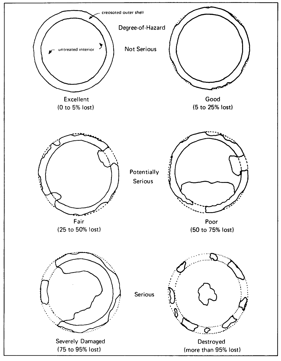
Figure A-1. Cross section of piles with different damage ratings.
A-5
Appendix B
INSPECTION, DOCUMENTATION, MAINTENANCE, AND CERTIFICATION
OF GRAVING DOCKS
INTRODUCTION . Detailed information is given in this
(3)
Copies of correspondence relative to
appendix for inspecting, reporting, maintaining, and,
matters affecting the capabilities of the dock or its
specifically, certifying graving docks, because this
material readiness.
information is no longer covered in a maintenance and
(4)
Reports of machinery derangements and
operation manual.
casualties to material.
(5)
Operational logs, if any, of the dock and
SCHEDULING. It is not necessary for all parts of a
its equipment.
dock to be inspected simultaneously. Each item shall
(6)
Operation manuals for the equipment.
be inspected at least once each year, except for
(7)
A record of repairs or improvements
machinery, such as pumps and capstans (see Table B-1
effected on machinery.
for detailed scheduling). Machinery that must be
(8)
Prints or drawings of the structure and
opened for inspection should be scheduled for
utilities of the dock. Plans and as-built specifications,
inspection at a time when it will not interfere with the
when available.
docking schedule. Advantage shall be taken of routine
pumping and flooding of the dock and caisson to inspect
Each activity shall prepare a Preventive
the machinery and equipment while they are in
Maintenance (PM) Manual for the mechanical
operation.
equipment (pumps, sluice gates, valves, ventilation,
etc.) for each graving drydock. The Manual should
DOCUMENTATION . The following documents shall be
include but is not limited to the following:
made available for study and use by the inspectors:
(1)
Location of all fittings.
(1)
Previous reports of preventive
(2)
Maintenance schedule for components,
maintenance inspections and control inspections.
including description of work
(2)
Copies of correspondence relative to
(3)
Overhaul frequency for each piece of
correction of deficiencies that were initiated or received
equipment (varies between 2 and 10 years)
since the last inspection.
B-1
(4)
Type, age, and manufacturer of installed
progressive failure.
equipment
(5)
Equipment usage and reliability histories
MAINTENANCE. Preventive maintenance is primarily
(6)
Backup equipment available
concerned with items that, if disabled, would (1)
(7)
Notes on overall condition and impact of
interfere with an essential operation of the graving
failure
drydock, (2) endanger life and/or property, or (3) involve
high cost or long lead time for replacement.
INSPECTION. Table B-2 lists specific items to inspect.
Maintenance work must be scheduled to conform to the
The inspectors shall observe the following procedures
operating schedule of a drydock. Maintenance work
when making these inspections.
which does not interfere with a dock operating schedule
should be performed when necessary. The following are
(1)
Thoroughly inspect every part of the
the principal elements of maintenance for a graving
drydock and every item of machinery and equipment to
drydock:
determine its condition (see Figure B-1 ).
(2)
Make free use of hammers for sounding
(1)
Patching cracks and grouting leaks in the
rivets, bolts, plates, and other parts, and of scrapers for
concrete dock body, including filling and discharge
removing paint to disclose metal surfaces. Use probes
culverts; weld repair of metal cracks and damaged
to determine the soundness of timber structures.
metal.
Hammers can be used to examine defective areas on
(2)
Cleaning, painting, and replacing metal
concrete surfaces.
guardrails, stanchions, gratings, and similar equipment.
(3)
Pay particular attention to leaks, and note
(3)
Repairing and replacing operating
if any materials are being carried in suspension.
equipment (such as motors and controls, pumps, valves,
(4)
Pay particular attention to the possibility
and sluice gates) and utility equipment (such as air,
of settlement of the drydock or adjacent land.
water, steam, electric power, and sewage).
(5)
Take soundings outboard of entrances to
(4)
Renewal of blocking.
determine whether there are any large holes or raised
(5)
Cleaning and painting of the drydock
areas that might indicate movement of earth from or
entrance closures and seats, and repair and
development of water-ways under the drydock floor.
replacement of its operating equipment.
(6)
Note any evidence of undue stress in
caisson structure, such as sprung plates, leaky rivets, or
The coating systems recommended for
bent frames, caused by unequal drydock settlement.
maintenance painting of drydock components are listed
in Table B-3. The methods for surface preparation and
If feasible, cracks and other similar faults should
their application are described in Chapter 7 of this
be repaired or photographed to determine the rate of
manual and in much greater detail in Reference 7-3 and
B-2
B-1. The latter gives detailed instruction for use of MIL-
shown to be effective by audit.
Facility certification shall be terminated as a result of the
CERTIFICATION . The objective of facility certification
following:
is to assure the safety of ships and personnel during
docking and undocking operations and the safety of
(1)
Major overhaul or repair.
ships while in dock. This certification does not cover
(2)
Broaching of the scope of the facility
other requirements of the facility, such as compressed
certification.
air, steam, electrical, and sewage services. Normally,
(3)
Expiration of tenure of facility certification.
the facility shall be certified for its maximum designed
(4)
Recognition of the existence of an unsafe
capacity. If the facility is certified for a loading of less
condition.
than this amount, the reason for choosing this value
shall be explained. The maximum designed capacity,
After certification, the facility must remain in the "as
unless otherwise stated, shall be based on a typical ship
certified" condition with full consideration being given to
loading.
normal wear and tear for the period of certification.
When required certification shall be submitted to
The general requirements for certification are:
the major Command with a copy to the appropriate
headquarters for each facility every five years. In the
(1)
Provide a description of the graving dock.
event major changes are made to the facility within this
The description must be based on the dock design as
five-year period, a revised certification application shall
presently constructed, including modification to date.
be submitted. As an option, a maintenance program
Provide data such as core borings and foundation data;
providing for a continuous certification without frequent
description of foundation, longitudinal and transverse
or regular resubmittals, except when significant changes
sections with appropriate elevations, and entrance
are made, can be implemented, with the stipulation that:
closure; information on the performance and adequacy
of the drydock pressure relief system; the effectiveness
(1)
A formalized and implemented
of the drainage features (blankets, filters, and
maintenance program exists and can be shown to be
underdrain); and irregularities which may indicate
effective by audit.
normal concentration of flow or subsurface erosion.
(2)
Operating procedures are maintained in
Original historical data would only be provided when
current and self-correcting accuracy as shown by in-
relevant to the present configuration.
process audit.
(2)
Provide a history of the successful
(3)
Control of design and other system
operation of the graving dock over the last five years.
changes are effected through a formalized and
(3)
Provide copies of Standard Operating
implemented Design (or change) Control Board and
Procedures for Docking and Undocking Vessels and
B-3
Standard Operating Procedures for Operating the
team must conduct a material survey. The material
Graving Docks.
survey shall include measurements for potential
(4)
Where activity disaster plans and firemain
corrosion and cathodic protection. Upon receipt of the
certification tests have already been submitted, include
survey, the conditional acceptance will be made a full
copies for information only.
acceptance.
(5)
An earthquake analysis shall be provided
A material survey by an independent team shall
in areas subject to seismic events.
be conducted at ten-year intervals. A yearly visual
survey of each facility must be conducted by in-house
On the basis of the above information, a
personnel and a report submitted. If any material
conditional certification of the facility will be given.
change occurs to the condition of the facility, the activity
Within the next three years, a professional engineer
must notify the certification organization.
B-4
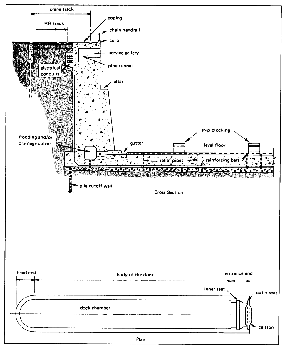
Figure B-1. Designation of drydock features.
B-5
Table B-1. Inspection Frequencies
Preventive
Control or
Preventive
Control or
Component
Maintenance
Engineering
Component
Maintenance
Engineering
Inspection
Inspection
Inspection
Inspection
Electrical:
Mechanical (cont'd):
Communication equip-
Sewage and plumbing
ment and controls
SA
A
system:
Distribution:
Fixtures
M
A
Transformers
-
A
Piping
M
A
Feeder and branch
Pumps
SA
A
circuit switchgear
SA
A
Valves
SA
A