FInite Element Analysis Guide Through ANSYS Wb v.16.2 by Syllignakis Stefanos, Petr Vosynek - HTML preview
Download the book in PDF, ePub, Kindle for a complete version.
 These parts will be transferred to Design Simulation as parts consisting of multiple bodies (volumes), but Shared Topology.
-
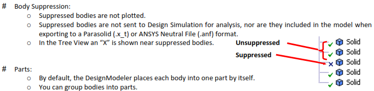
To form a new part, select two or more bodies from the graphics screen and use
 Tools Form New Part.
- The Form New Part option is available only when bodies are selected and you are not in a feature creation or feature edit state.
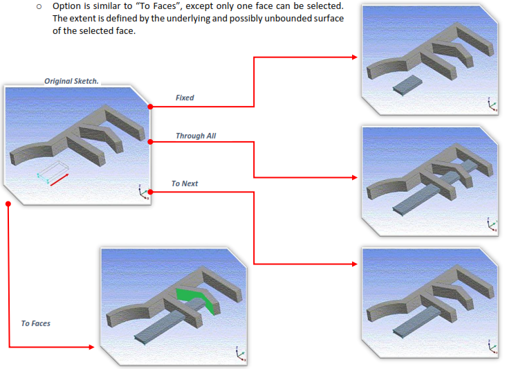
# Fixed:
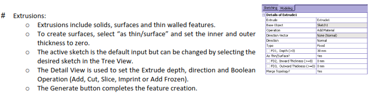
 Fixed extents will extrude the profiles the exact distance specified by the depth property. The feature preview shows an exact representation of how the feature will be created.
# Through All Type:
Will extend the profile through the entire model.
When adding material the extended profile must fully intersect the model.
# To Next:
Add will extend the profile up to the first surface it encounters.
Cut, Imprint and Slice will extend the profile up to and through the first surface or volume it encounters.
# To Faces:
Allows you to extend the Extrude feature up to a boundary formed by one or more faces.
For multiple profiles make sure that each profile has at least one face intersecting its extent. Otherwise, an extent error will result.
The “To Faces” option is different from “To Next”. To Next does not mean “to the next face”, but rather “through the next chunk of the body”.
The “To Faces” option can be used with respect to faces of frozen bodies.
# To Surface:
# Sweep:
- Solids, Surfaces and thin walled features can be created by using this feature to sweep a profile along a path.
- Scale and Turns properties can be used to create helical sweeps.
Scale: Tapers or expands the profile along the path of the sweep.
Turns: Twists the profile as sweeps along the path.
A negative value for Turns will make the profile rotate about the path in the opposite direction.
- Alignment:
Path Tangent: Reorients the profile as it is swept along the path to keep the profile in the path’s tangent direction.
Global: The profile’s orientation remains constant as it is swept along the path, regardless of the path’s shape.
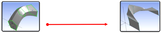
# Skin/ Loft:
- Takes a series of profiles from different planes to create 3D Geometry fitting through them.
A profile is a sketch with one closed or open loop or a plane from a face.
All profiles must have the same number of edges.
Open and closed profiles cannot be mixed.
All profiles must be of the same type.
- Sketches and planes can be selected by clicking on their edges or points in the graphics area, or by clicking on the sketch or plane in the feature tree.
- After selecting an adequate number of profiles, a preview will appear showing he selected profiles and the guide polygon.
- The guide polygon is a gray poly-line which shows how the vertices between the profiles will line up with each other.
- Skin/ Loft operation relies heavily on Right Mouse Button menu choices.
# Point:
- The Point feature allows for controlled and fully dimensioned placement of points relative to selected model faces and edges.
- Select a set of base faces and guide edges.
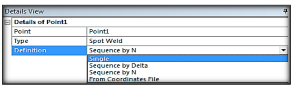
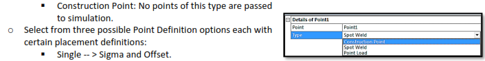
- Select the Point (analysis) Type:
Spot Weld: Used for “welding” together otherwise disjointed parts in an assembly.
Point Load: Used for “hard points” (nodal points) in the analysis.
Sequence By Delta -- > Sigma, Offset, Delta.
Sequence By N -- > Sigma, Offset, N, Omega.
From Coordinates File -- > Formatted text file, similar to 3D curve.
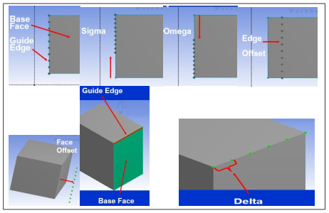
- Sigma: The distance between the beginning of the chain of guide edges and the placement of the first point.
- Edge Offset: The distance between the guide edges and the placement of the spots on the set of base faces.
- Delta: The distance, measured on the guide edges, between two consecutive points, for the Sequence By Delta option.
- N: The number of points to be placed, relative to the chain of guide edges, in case of the Sequence By N option.
- Omega: The distance between the end of the chain of guide edges and the placement of the last spot, for the Sequence By N option.
# Examples: