Applications of Nonlinear Control by Meral Altınay - HTML preview
Download the book in PDF, ePub, Kindle for a complete version.
(45)
The speed of dc machine depends on armature voltage and field current, as shown in (45). In
field control, the armature voltage is kept constant and the field current is set. The relation
between speed and field current is indirect proportion. However, in armature control, the
relation between armature voltage and speed is directly proportional. Furthermore, in
armature control, the field current is kept constant and the armature voltage is set.
In this chapter, the armature control of dc machine is realized.
The speed control loop is added to nonlinear control loop. Firstly, the actual speed is
compared with reference speed then the speed error is regulated by PI controller and after
that its subtraction from armature current, the reference current is obtained. The reference
current obtained by speed loop, is added to nonlinear control loop instead of reference
current, which is obtained by the comparison of the square of reference voltage and actual
voltage.
In Fig. 9, speed control loop is shown.
Fig. 9. Armature speed control loop of dc machine
7. Simulations
Simulations are realized with Matlab/Simulink. Line voltage is taken 220 V, 60 Hz. The
switching frequency is also chosen 9 kHz. L filter and controllers parameters are shown in
Table.1 and Table.2.
Simulation diagram is shown in Fig.10. By simulation, steady-state error and settling time of
dc motor speed, harmonic distortions and shapes of line currents and unity power factor are
examined.


Application of Input-Output Linearization
13
Passive Components
L Filter
Dc-Link
L (H)
R (Ω)
(μF)
0.0045 5.5
2200
Table 1. Values of L filter components
Controllers
Speed Controller
Input-output current controller
(10 )
(10 )
10 0.01 30 50
Table 2. Values of controllers
Tork
TL
m
I_abc
g
La
Lla
Ta
+
Mta
A+
dc
A-
A
Lb
Llb
Tb
+
Mtb
B
v
-
F+
F-
V bus (V)
-
Lc
Llc
Tc
Mtc
C
Universal Bridge
Inductors
Measures
iq
0
In1 v ia
vdc
Pulses
id
current ref
m
c
1
2
a
b
c
v ib
Mt
Mt
Mt
In2
vabc1
I_ab
v ic
vabc
vabc
iabc
I armature
speedref
grid
nonlinear controller
speed controller
Speedref
Ta
Tb
Tc
Discrete,
v1
v2
v3
Ts = 5e-006 s.
pow ergui
Fig. 10. Simulation diagram of dc machine controller in Simulink
Fig.11 shows the structure of input-output controller diagram.
5
abc
Id
iabc
dq0
Iq
ud
sin_cos
Idref
Iqref
uq
dq0
abc - dq
vdc
abc
Uref Pulses
1
2
input - output
sin_cos
Pulses
id
control er
0
4
abc sincos
1
dq0 - abc
vabc1
iq
3
angle
vdc
generator
Fig. 11. Input-output controller diagram
14
Applications of Nonlinear Control
Equation (41) is written in the block of input-output controller which is shown in Fig.12.
1
Id
((-L)/u[5])*((-w*u[2])+((R*u[1])/L-(E/L))-(k*(u[1]-u[3])))
1
2
ud
Iq
3
Idref
4
((-L)/u[5])*((w*u[1])+((R*u[2])/L)-(K*u[2]))
2
Iqref
uq
5
vdc
Fig. 12. Input – output controller
Fig. 13 shows the speed controller of dc machine.
PI
1
I armature
current ref
2
1
m
field
tork
2
speedref
Fig. 13. Speed controller of dc machine
Fig.14 shows the dc machine speed. Reference speed value is changed from 150 rad/s to
200rad/s at 0.5 s. Settling time to the first reference is shorter than 0.15 s, but settling time of
second reference is 0.1 s.
Fig. 15 shows the steady-state error of dc machine speed. It is seen that the steady – state
error changes between ±2 rad/s.
The one phase voltage and current is shown in Fig. 16. It is also seen that unity power factor
is obtained but not as desired.
Fig. 17 shows the line currents. The shapes of line currents are sinusoidal.
Application of Input-Output Linearization
15
dc machine speed
250
200
s)
150
speed(rad/
100
50
0 0
0.1
0.2
0.3
0.4
0.5
0.6
0.7
0.8
0.9
time(s)
Fig. 14. Dc machine speed
156
dc machine speed
154
152
s)d/ra 150
d(
spee 148
146
144
0.3 0.31 0.32 0.33 0.34 0.35 0.36 0.37 0.38 0.39 0.4
time(s)
Fig. 15. Steady-state error of dc machine speed
16
Applications of Nonlinear Control
300
voltage
current
200
)
100
),(A(Ve, 0
agnitudM -100
-200
-300
0.28
0.29
0.3
0.31
0.32
0.33
0.34
0.35
time(s)
Fig. 16. One phase voltage and current
40
30
20
10
)A
0
ent (rr
Cu -10
-20
-30
phase a
-40
phase b
phase c
0.13
0.135
0.14
0.145
0.15
time(s)
Fig. 17. Three-phase phase current


Application of Input-Output Linearization
17
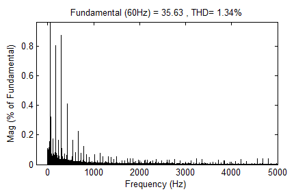
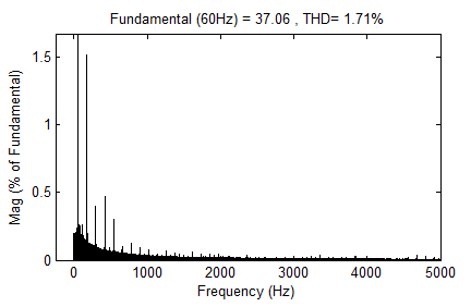
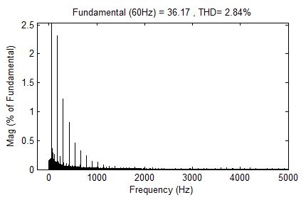
Fig. 18 shows the harmonic distortions of line currents. Line currents include high order
harmonic contents. However, total harmonic distortion value (THD) is under the value that
is defined by standards. THD of line currents are %1.34, %1.71 and %2.84.
Ia
Ib
Fig. 18. Harmonic distortions of line currents
18
Applications of Nonlinear Control
8. Conclusion
In this chapter, simulation of dc machine armature speed control is realized. Dc machine is
fed by voltage source rectifier which is controlled input – output linearization nonlinear
control method. Furthermore, for the speed control, dc link voltage is regulated by the dc
machine speed control loop. The control algorithm of voltage source rectifier and dc motor
speed are combined. The required reference current for voltage source rectifier is obtained
by speed control loop. Simulations are carried through Matlab/Simulink. By means of the
simulation results, the speed of dc machine, line currents harmonic distortions and power
factor of grid are shown. It is shown that the voltage source rectifier with dc machine as a
load provides lower harmonic distortion and higher power factor. Furthermore, dc machine
speed can be regulated.
9. References
Bal, G. (2008). Dogru Akım Makinaları ve Suruculeri, Seckin, ISBN 978-975-02-0706-8, Sihhiye,
Ankara, Turkey
Bates, J.; Elbuluk, M,E. & Zinger, D,S. (1993). Neural Network Control of a Chopper-Fed Dc
Motor, IEEE Power Electronics Specialist Conference PESC02, Vol 3, pp. 893, ISBN 0-
7803-1243-0, Seattle, Washington, USA, June, 1993
Blasko, V. & Kaura, V. (1997). A New Mathematical Model and Control Three-Phase ac-dc
Voltage Source Converter, IEEE Transactions on Power Electronics, Vol 12, January,
1997, pp. 78-81, ISSN 0885-8993
Bose, B,K. (2002). Modern Power Electronics and Ac Drives, Prentice Hall, ISBN 0-13-016743-6,
New Jersey, USA
Dai, K.; Liu, P. ; Kang, Y. & Chen, J. (2001). Decoupling Current Control for Voltage Source
Converter in Synchronous Rotating Frame, IEEE PEDS, pp. 39-43, ISBN 0-7803-
7233-6, Indonesia, January-February, 2001
Dannehl, J.; Fuchs, F,W. & Hansen, S. (2007). PWM Rectifier with LCL filter Using Different
Control Structures, EPE Aalborg, pp. 1-10, ISBN 972-92-75815-10-2, Aalborg,
October, 2007
Dixon, J,W. & Ooi, B,T. (1988). Indirect Current Control of a Unity Power Factor Sinusoidal
Current Boost Type Three-phase Rectifier, IEEE Transaction of Indisturial Electronics,
Vol.35, Nov, 1988, pp. 508-515, ISSN 0278-0046
Dixon, J,W. (1990). Feedback Control Strategies for Boost Type PWM Rectifiers . Proceedings
of IEEE Colloquium in South America, pp. 193-198, ISBN 0-87942-610-1, September,
1990
Fitzgerald, A,E.; Kingsley, C,Jr. & Umans, S,D. (2003). Electric Machinery, McGraw Hill, ISBN
0-07-112193-5, New York, USA
Holtz, J. (1994). Pulse Width Modulation for Electronic Power Conversion, Proceedings of the
IEEE, Vol 82, August 1994, pp. 1194-1214, ISSN 0018-9219
Isidori, A. (1995). Nonlinear Control Systems, Springer-Verlag, ISBN 3-540-19916-0,
Heidelberg New York
Kazmierkowski, M,P.; Krishnan, R. & Blaabjerg, F. (2002). Control in Power Electronics:
Selected Problems, Elsevier Science, ISBN 0-12-402772-5, San Diego, California,
USA
Application of Input-Output Linearization
19
Kim, D,E. & Lee, D,C. (2007). Feedback Linearization Control of Three-Phase Ac/Dc PWM
Converters with LCL Input Filters, International Conference on Power Electronics
ICPE’07, pp. 766-771, ISBN 978-1-4244-1871-8, Daegu, South Korea, October,
2007
Khalil, H,K. (2000). Nonlinear Systems, Pearson Education, ISBN 0-13-122740-8, New Jersey,
USA
Krishnan, R. (2001). Electric Motor Drives: Modeling, Analysis, and Control, Prentice Hall, ISBN
0-13-091014-7, New Jersey, USA
Kömürcügil, H. & Kükrer, O. (1998). Lyapunov Based Control of Three-Phase PWM Ac-Dc
Voltage-Source Converters, IEEE Transactions on Power Electronics, Vol 13,
September 1998, pp. 801-813, ISSN 0885-8993
Lee, D,C.; Lee, G,M. & Lee, K,D. (2000). Dc Bus Voltage Control of Three Phase Ac-Dc PWM
Converters Using feedback Linearization, IEEE Transactions on Industry Application,
Vol 36, May-June 2000, pp. 826-833, ISSN 0993-9994
Lee, T,S. (2003). Input-Output Linearizing and Zero Dynamics Control of Three-Phase Ac-
Dc Voltage Source Converters, IEEE Transactions on Power Electronics, Vol 18,
January 2003, pp. 11-22, ISSN 0885-8993
Lindgren, M. (1998). Modelling and Control of Voltage Source Converters Connected to the
Grid, PHDs Thesis Faculty of Chalmers University of Technology, ISBN 91-7197-710-4,
Goteborg, SWEEDEN, November, 1998
Liserre, M.; Blaabjerg, F. & Hansen, S. (2005). Design and Control of an LCL Filter Based
Three-Phase Active Rectifier, IEEE Transactions on Industry Application, Vol 41,
September-October 2005, pp. 1281-1291, ISSN 0993-9994
Mao, H.; Boroyevich, D. & Lee, F.C. (1998). Novel Reduced-Order Small-Signal Model of
Three-Phase PWM Rectifiers and its Application in Control Design and System
Analysis, IEEE Transactions on Power Electronics, Vol 13, May 1998, pp. 511-521,
ISSN 0885-8993
Mihailovic, Z. (1998). Modeling and Control Design of VSI_ Fed PMSM Drive Systems with
Active Load, Master Thesis Faculty of Virginia Polytechnic and State University,
Blacksburg, Virginia, USA, September, 1998
Ooi, B,T.; Salmon, J,C. ; Dixon, J,W. & Kulkarini, A,B. (1987). A three-phase Controlled
Current PWM Converter with Leading Power Factor, IEEE Transaction of Indistury
Application, Vol.IA-23, Jan-Feb 1987, pp. 78-81, ISSN 0093-9994
Sehirli, E. & Altınay, M. (2010). Simulation of Three-Phase Voltage Source Pulse Width
Modulated (PWM) LCL Filtered Rectifier Based on Input-Output Linearization
Nonlinear Control, IEEE International Conference on Electrical and Electronic
Equipment OPTIM’2010, pp. 564-569, ISBN 978-1-4244-7019-8, Brasov, Romania,
May, 2010
Slotine, J,J,E. & Li, W. (1991). Applied Nonlinear Control, Prentice Hall, ISBN 0-13-040890-5,
New Jersey, USA
Sousa, G,C,D. & Bose, B. (1994). A Fuzzy Set Theory Based Control of a Phase - Controlled
Converter Dc Machine Drive, IEEE Transactions on Industry Application, Vol 30,
January-February, 1994, pp. 34-44, ISSN 0993-9994
Wu, R.; Dewan, S,B. & Slemon, G,R. (1988). A PWM ac to dc Converter with Fixed Switching
Frequency, Conference Recordings 1988 IEEE-IAS Annual Meeting, Vol 1, October,
1988 pp. 706-711, Pittsburgh, PA, USA
20
Applications of Nonlinear Control
Wu, R.; Dewan, S,B. & Slemon, G,R. (1991). Analysing of ac to dc Voltage Source
Converter Using PWM with Phase and Amplitude Control, IEEE Transactions
Industirial Applications, Vol 27, March-April, 1991, pp. 355-364, ISSN 0093-
9994
Ye, Z. (2000). Modelling and Control of Parallel Three-Phase PWM Converters, PHDs Thesis
Faculty of Virginia Polytechnic and State University, pp. 9-20, Blacksburg, Virginia,
USA, September, 2000
0
2
Lyapunov-Based Robust and Nonlinear
Control for Two-Stage Power Factor
Correction Converter
Seigo Sasaki
National Defense Academy
Japan
1. Introduction
Many power electronic system designs focus on energy conversion circuit parameters rather
than controller parameters which drive the circuits. Controllers must be designed on the
basis of circuit models, which are generally nonlinear systems (Brockett & Wood (1974)), in
order to improve performance of controlled systems. The performance of controlled systems
depend on nominal models to design the controllers. More broad class of models controllers
are designed for, better control performance may be given. Many works (e.g. Kassakian
et al. (1991)) design controllers for linearized models because it is not easy to concretely
design controllers for the nonlinear models. Controller design in consideration of nonlinear
models has been discussed since a work by Banerjee & Verghese (2001) because a research on
nonlinear controller design has grown in those times.
This chapter systematically designs a robust controlled power converter system on the
basis of its nonlinear model. Concretely, a two-stage power factor correction converter,
that is a forward converter (FC) with power factor corrector (PFC), is designed.
The
systematic controller design clearly analyzes the behavior of nonlinear system to improve
the performance.
A work by Orabi & Ninomiya (2003) analyzes a stability of single-stage PFC for variations
of controller gain on the basis of its nonlinear model. On the basis of the work by Orabi &
Ninomiya (2003) that regards a load of PFC as constant, a work by Dranga et al. (2005) for a
two-stage PFC focuses on a point that a load of PFC part is not pure resistive and analyzes a
stability of the converter.
A work by Sasaki (2002) discusses an influence between a FC part and a PFC part in
a two-stage PFC. A work by Sasaki (2009) clearly shows that a source current reference
generator plays an important role in a synthesis for a single-stage PFC. For the works by
Sasaki (2002; 2009), this chapter shows how to decide synthesis parameters of robust linear
and nonlinear controllers for a two-stage PFC in more detail.
The controller synthesis step, that is this chapter, is organized as follows. First, the converter is
divided into two parts which consists of a FC part and a PFC part by considering an equivalent


22
Applications of Nonlinear Control
2
Nonlinear Control
circuit of tr