Simple Projects for ECE Students by S.Srinath - HTML preview
Download the book in PDF, ePub, Kindle for a complete version.
Design of 3rdOrder Coupled Line Bandpass Filter for Wireless Application using Agilent ADS
S.Srinath
B.Tech Alumnus, School of Electronics Engineering, Vellore Institute of Technology, Vellore, Tamil Nadu, India.
ABSTRACT:Design of a parallel-coupled microstrip bandpass filter is presented in this paper. The aim of this paperis to present the design technique, parameter analysis, real prototype fabrication and measurement results at asimulation frequency of 5.85GHz. Half wavelength long resonators and admittance inverters are used todesign the filter. The filter is simulated using Agilent ADS (Advanced Design System) 2011.
KEYWORDS:Bandpass filter; Microstrip; 5.85 GHz; Parallel Coupled Line; Microwave Engineering; Agilent ADS simulator.
I. INTRODUCTION
Filters are an essential part oftelecommunications and radar systems. Of its low-cost fabrication, easy integration and simple designing procedure,the parallel coupled-line/edge-coupled filters are widely used in microwave microstrip circuits with a requiredbandwidth up to 20 % of central frequency.
The parallel coupled transmission lines can be used to construct many types of filters. Fabrication of multisection bandpass or bandstop coupled line filters isparticularly easy in microstrip or stripline form for bandwidths less than about20%.Wider bandwidth filters generally require very tightly coupled lines, whichare difficult to fabricate.A two- port network can be formed from a coupled line section by terminating two of the four ports with either open or short circuits, or by connecting twoends.
A bandpass filter only passes the frequencies within a certain desired bandand attenuates others signals whose frequencies are either below a lower cutoff frequency or above an upper cut-offfrequency. The range of frequencies that a bandpass filter let’s to pass through is referred as passband. A typicalbandpass filter can be obtained by combining a low-pass filter and a high-pass filter or applying conventional low passto bandpass transformation. The architecture demonstrated here is a coupled line type filter, since this is among themost practical and common filter types which can meet the stated specifications.
The filter response will be based on the Chebychev transfer function. Chebychev type filters are popular for their high selectivity, i.e., they have a relatively fast signal cut off between pass and stop band.
II. RELATED WORK
This paper presents the design of a parallel-coupled microstrip bandpass. The design is based on the use of half wavelong resonators and admittance inverters. The center frequency of 5.85 GHz is selected, the bandwidth (BW) is about 200Mhz, the minimum attenuation amounts to -20 dB and the pass-band ripple is obtained equal to0.5 dB.The design technique, parameter analysis, real prototype fabrication and measurement results of a 3rd ordercoupled line bandpass filter at a simulation frequency of 5.85GHz is presented in this paper.
III. THEORY
A general layout of a parallel coupled microstrip bandpass is shown in figure 1. The filter structure consists of opencircuited coupled microstrip lines. These coupled lines are quarter wavelength,  long and are equivalent to shuntresonant circuits. The coupling gaps correspond to the admittance inverters in the low-pass prototype circuit. Even- andodd- mode characteristic impedances of parallel-coupled half-wave resonators are computed using admittance inverters.These even- and odd- mode impedances are then used to compute physical dimensions of the filter. Now consider abandpass filter composed of a cascade of N + 1 coupled line sections, as shown in Figure 1. The sections arenumbered from left to right, with the load on the right, but the filter can be reversed without affecting the response.Since each coupled line section has an equivalent circuit of the form, the equivalent circuit of the cascade is as shown in figure 2.
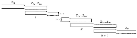
Figure 1. : Layout of an (N + 1)-section coupled line bandpass filter.
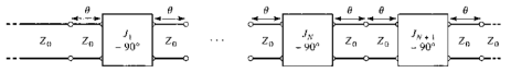
Figure 2. : Using the equivalent circuit of Figure 1. for each coupled line section.
IV. IMMITTANCE INVERTER
Immittance inverters play a very important role in filter design. They are used to transform a filter circuit into anequivalent form that can be easily implemented using various microwave structures. Immittance inverters are eitherimpedance or admittance inverters. Making use of the properties of immittance inverters, bandpass filters may berealized by series (L-C) resonant circuits separated by impedance inverters (K) or shunt (L-C) parallel resonant circuitsseparated by admittance inverters (J). To