existing stringers which are to remain in the structure.
2.3.1.2 Pile Caps. Decayed or damaged pile caps
Connections between replacement and existing stringers
should be replaced with properly treated members as
shall be made directly over a pile cap and they should
described in 2.1.4. Replacement caps shall be the
be bolted or pinned to the pile cap. Decayed or
same size and length as the original member unless
damaged
redesigned.
2.3.1.3 Braces. Diagonal braces that have been
attacked by fungi or marine borers or have been broken
2-7
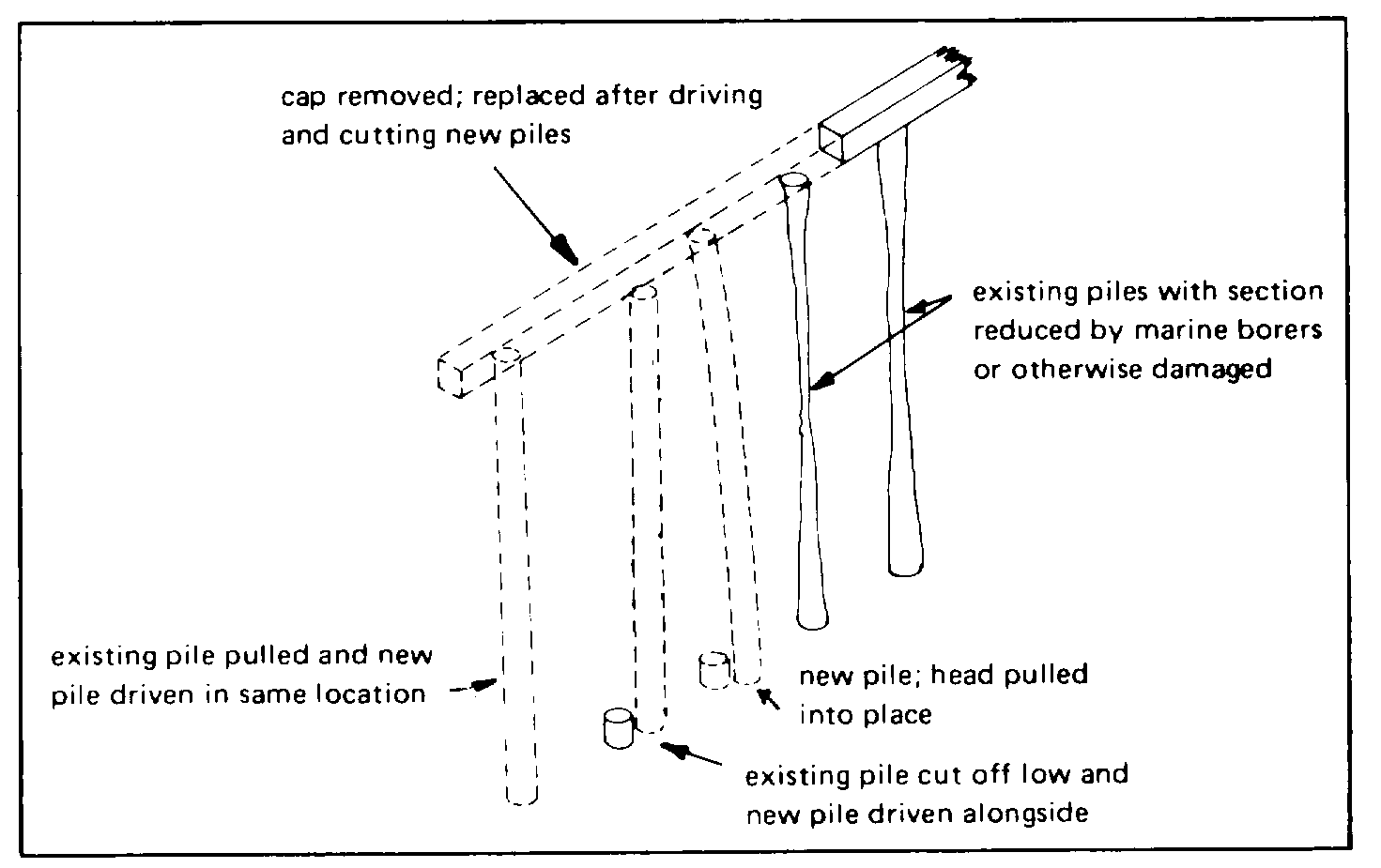
Figure 2-7. Wood pile replacement.
areas of long stringers can be removed and replaced
with properly treated new sections. Again, splices
should be made directly over a pile cap; splices in
2.3.1.7 Decking. Decking over which vehicular and
adjacent stringers should be staggered where possible.
pedestrian traffic passes should be replaced when its
A typical splice is shown in Figure 2-8.
top surface becomes excessively uneven, hazardous, or
worn to a point of possible failure. It should be replaced
2.3.1.5 String Pieces. The string piece, sometimes
with properly treated quarter-sawn timber. Spacing
referred to as the curb, bullrail, or backing log, is
between decking planks should be provided for
subjected to much wear and to constant wettings and
ventilation and drainage. Decking for relieving
dryings. Properly treated replacement sections should
platforms which have an earth fill should be laid in a
be long enough to reach between a minimum of two
double layer without spacing between the planks.
bents. New preservative-treated blocks, 2 to 3 inches
thick, should be placed under each replacement section
2.3.1.8 Fire Curtain Walls. Wood fire curtain walls are
on 3-to-4-foot centers to provide for drainage. If any
usually made of two layers of planking which run
part of the lower string piece has deteriorated, the entire
diagonally to one another. All deteriorated planks
piece of timber should be replaced (see Figure 2-9).
should be replaced to restore the wall to its original
condition - as airtight as possible.
2.3.1.6 Chocks. Deteriorated chocks should be
replaced by properly treated, tightly fitting chocks that
are bolted to one string piece or to a waler below the
2-8
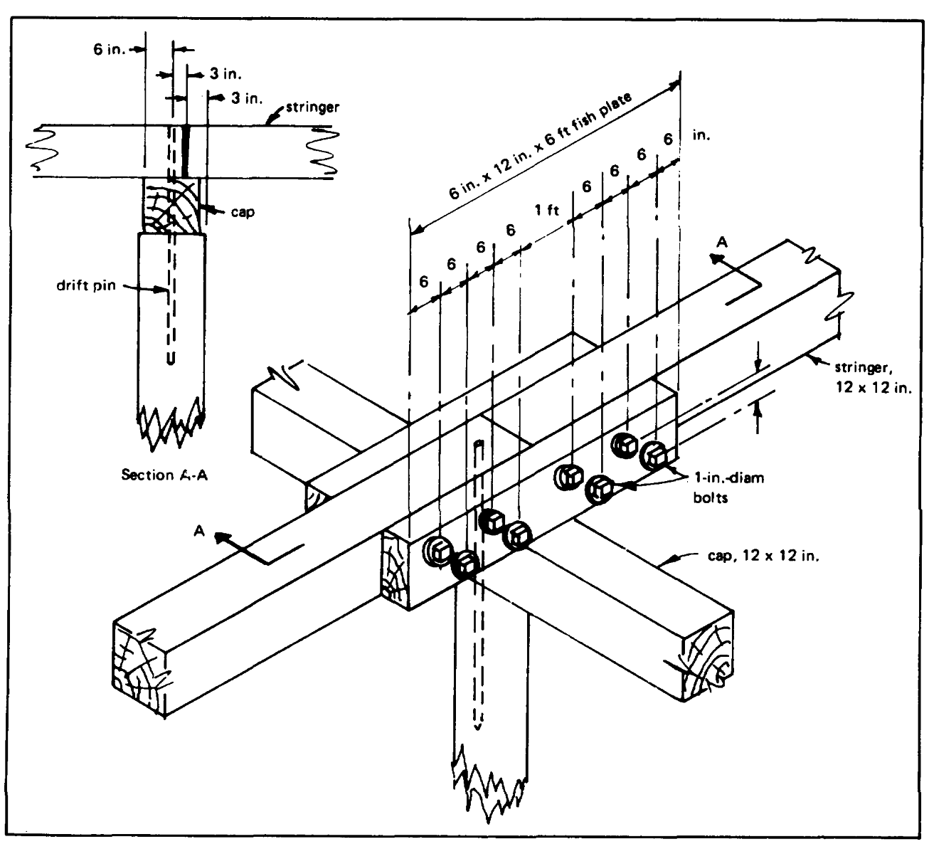
Figure 2-8. Stringer splice.
2.3.1.9 Fender Piles. Decayed, marine borer attacked,
2.3.1.10 Sheeting. Piers and quay walls may have
or broken fender piles that cannot be adequately
wood sheet pile bulkheads to retain fill on the shore
repaired should be pulled and replaced with a properly
side. Deterioration of these bulkheads results in loss of
treated new pile. Installation of a steel "shoe" on the
fill and settlement of the material above the affected
outer (wearing) surface of each fender pile is
areas. In the early stages of deterioration, repairs can
recommended. Adequate camel logs should be
be made by using a plastic marine splash-zone
provided.
compound, such as an epoxy-polyamide.
2-9
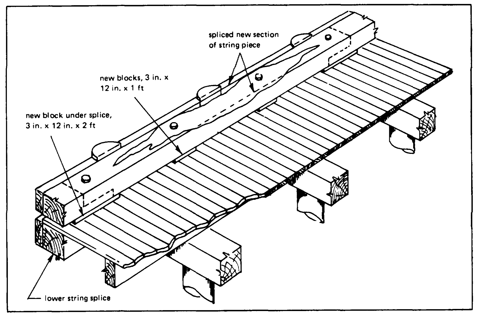
Figure 2-9. Repair of string piece.
When deterioration is more extensive, sheet piling is
2.3.1.11 Dolphins. The maintenance of timber dolphins
driven to form a new bulkhead a minimum of 1 foot
includes the replacement of fastenings and any wire
behind the existing one in order to avoid the driving
rope wrapping that has become defective through
frames or wales attached to it. Steel sheet piling, driven
corrosion or wear. The maintenance of a catwalk that
to a minimum of 3 feet below the toe of the deteriorated
connects dolphins includes the replacement of damaged
wood sheeting, is normally used for the new bulkhead.
or deteriorated timbers; steel members should be
The fill at the inside edge is normally removed before
cleaned and painted, or replaced. The repair of
driving the new sheet piling. When this is done, a
dolphins includes replacement or rehabilitation of piles,
concrete cap should be placed over the new sheeting to
wire rope wrappings, and blocking. If it is necessary to
form a seal with the existing construction.
replace any piles, the fastenings should be removed
only as far
2-10

Figure 2-10. 100% deterioration of chocks, lower wales, and fender piles.
as is necessary to release the piles that are damaged.
are driven, the center cluster should be brought together
Care should be taken to drive the new piles at the
first, fitted, chocked, bolted, and pinned; when all rows
proper angle so that they will not have to be pulled too
have been properly fitted, etc., they are then wrapped
far to fit them in place. The size of piles to be replaced
with wire rope. All cuts in piles for fittings, bolts, and
should be carefully noted, particularly at the head or
wrappings should be thoroughly field-treated with
intermediate point where they are fitted together with the
creosote. These cuts should be avoided if at all
other piles. Much trouble in cutting and fitting the
possible, however, because field treatment with
replacement piles can be avoided by selecting piles with
creosote gives only marginal protection against marine
the proper size head. All replacement piles should be
borer attack.
driven before any are brought together. After all piles
2-11
borer attack, a flexible PVC barrier may be installed
(Figure 2-12). An in-place barrier not only prevents
further attack on a pile, but it also creates a stagnant
area between it and the pile surface, thus killing
organisms already present on or within the pile. In this
method, the pile is sheathed with a prefabricated unit
consisting of a 30-mil PVC sheet with a full-length, half-
round apitong wood pole piece attached to each vertical
edge. Lengths of flexible polyurethane foam, 1/2 x 3/6
inch, are stapled about 1 inch from the upper and lower
horizontal edges. When only the intertidal area is to be
sheathed, the PVC wrap is placed around the pile, and
the pole pieces are fitted together with one inserted into
a pocket attached to the bottom of the other. The
excess material is rolled on the combined pole pieces
and tightened around the pile with a special ratchet
wrench. Aluminum alloy nails are driven through the
rolled material and the pole pieces to secure the wrap
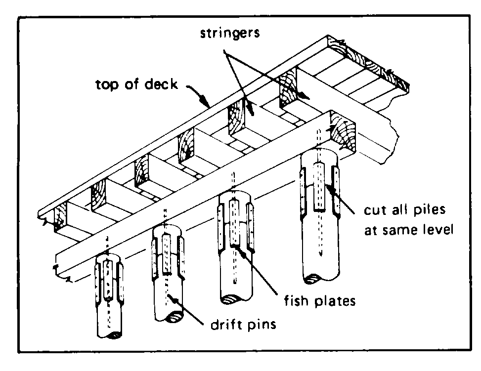
Figure 2-11. Replacing tops of piles.
initially. Then rigid plastic bands are nailed at the top
and bottom directly over where the polyurethane foam is
2.3.2 REPAIR
located under the wrap. Additional bands are installed
on equidistant centers between the top and bottom
2.3.2.1 Decayed Bearing Piles. The decayed top of a
bands. For protection extending to the mud line,
wood bearing pile can be repaired by cutting off the
approximately 12 inches of soil is excavated around the
damaged portion and fumigating the exposed cut-off to
pile, and the wrap is placed around the pile, lowered into
destroy any remaining hyphal threads. A section of
the excavated area, and secured as above. Then the
sound timber is installed and secured with epoxy cement
excavated area is backfilled with soil. When it is
or drift pins and fish plates to build the pile to the proper
necessary to wrap a pile that has creosote bleeding from
its surface, a sheet of polyethylene film is stapled to the
pile surface prior to installing the PVC wrap. (Creosote
2.3.2.2 Marine-Borer-Damaged Bearing Piles. Wood
will soften and swell PVC, but it does not affect
bearing piles that have lost 10 to 50% of their cross-
polyethylene.)
sectional area can be repaired by any of several
methods.
2.3.2.2.2 Concrete Barrier. When a diver or ultrasonic
inspection reveals that a pile has lost approximately 15
2.3.2.2.1 Flexible Barrier. When a diver or ultrasonic
to 50% of its cross-sectional area because of marine
inspection reveals that a pile has lost approximately 10
borer attack, a reinforced concrete barrier may be
to 15% of its cross-sectional area because of marine
installed.
2-12
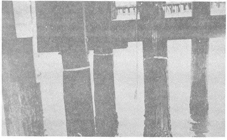
Figure 2-12. A flexible PVC barrier installed on wooden piles.
Various types of metal, nylon mesh, and pitch-
where undamaged wood is present, and the section is
impregnated fiber tube forms can be used. Two very
removed from the structure. In one patented method, a
important requirements for installations of this type are
specially designed, partly reusable form is clamped to
(1) a tight bottom seal between the form and the pile,
the pile stub and to the pile cap. Grout is pumped
and (2) a grout-dispensing pipe that extends to the very
through a hose connected to a nipple in the lower form
bottom of the form so that seawater within the form can
clamp and is continued until the grout reaches the pile
be pushed up and out by the rising column of pumped-in
cap. When the concrete has set, the upper and lower
grout.
form clamps are removed, and the expendable form
tube is left in place.
Another system uses a reinforced plastic jacket
which is placed to within 1/8 inch of the pile surface. A
2.3.2.3 Braces. A diagonal brace, which extends into
two-component resin mix is prepared, an equal part of
the water and has been lightly attacked by marine
fine sand is added, and this mortar is poured slowly into
borers, can be saved by (1) removing the bolt which
the void to replace the water.
secures it to the pile, (2) wrapping the freed end with 20-
mil flexible PVC sheet in a manner similar to applying
2.3.2.2.3 Replace Section. Replacement of damaged
electrical tape to a cut-off wire, (3) driving the bolt
wood pile sections with a reinforced concrete pile
through the wrapping and through the existing hole, and
section can be accomplished as follows: soil is
(4) rebolting the brace to the pile.
excavated at the mud line, the damaged pile is cut off
2-13
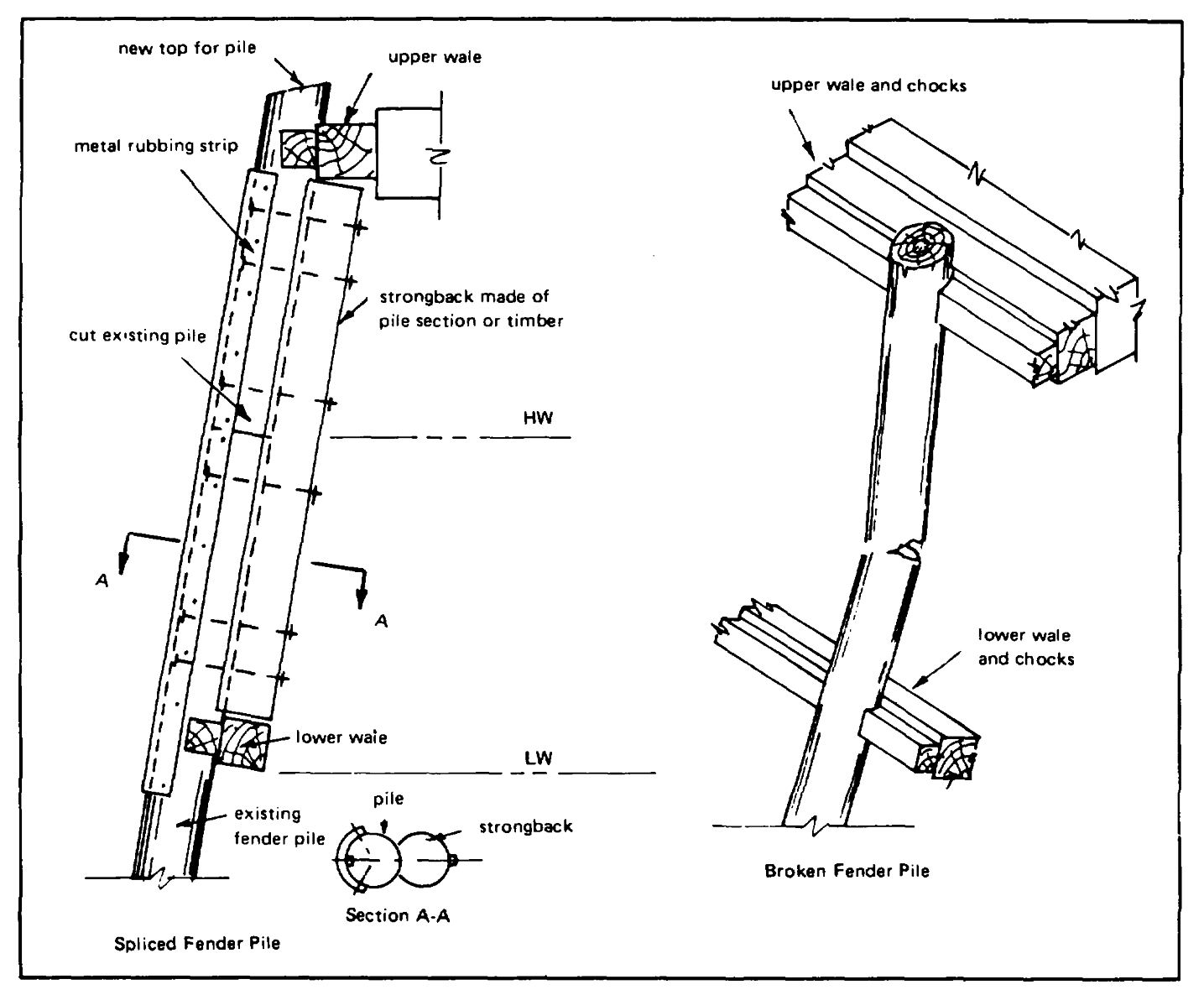
Figure 2-13. Fender pile repair.
2.3.2.4 Fender Piles. Fender piles that have been
and bolted in place directly behind the fender pile and
broken between the top and bottom wales can be
between the top and bottom wales. A metal "shoe"
repaired by cutting off the pile just below the break,
(wearing strip) should be attached to the wearing edge
installing a new section of pile, and securing w; n epoxy
of each fender pile (see Figure 2-13).
cement. A strongback (pile or timber section) is fitted
2-14
CHAPTER 3- CONCRETE STRUCTURES
SECTION 1. CONCRETE TECHNOLOGY
3.1.1 DEFINITION OF CONCRETE . Concrete is a
and gravel, crushed rock, or mixtures of them. Other
mass of sand, gravel, crushed rock, or other aggregate
aggregates, such as blast-furnace slags, manufactured
bonded together by a hardened paste of hydraulic
sand, or crushed coral, are used when the more
cement and water. When properly proportioned, mixed,
commonly used aggregate is unavailable. The
and consolidated, these ingredients form a workable
aggregate portion generally constitutes about 75% of the
mass which can be placed into a form of desired size
volume of the concrete. Particle size is usually limited
and shape. The water present reacts with the cement to
to three-fourths the distance between reinforcing bars or
convert the concrete to a hard and durable product.
one-fifth the minimum dimension, and never more than
3/4 inch. Particles of various sizes should be uniformly
3.1.2 COMPONENTS OF CONCRETE
distributed throughout the mass and properly graded for
dense packing. The quality and gradation of aggregate
3.1.2.1 Cement. Cement is a kiln-dried and finely
should conform to ASTM requirements.
pulverized mixture of natural earth materials used as a
bonding ingredient in concrete or mortar. Of the five
3.1.2.3 Water. Water not only changes the concrete
types of cement defined by the American Society for
mixture to a workable consistency suitable for placing in
Testing and Materials (ASTM), only Types II and V
a mold or forms for a desired size and shape, but it is a
should be considered for concrete structures that come
necessary ingredient to react with the cement, called
into contact with seawater. Type V is the recommended
hydration, which converts the cement to a hardened
product for such structures because of its high
mass. The ratio of water to cement (W/C) is largely
resistance to sulfate attack (a form of disintegration
responsible for determining the strength of the concrete.
occurring in seawater and other high salt environments).
This ratio, which excludes water absorbed by the
The more commonly produced Type II, which has a
aggregate, is expressed as a decimal (on a weight ratio
moderate resistance to sulfate attack, can be used when
basis) or as gallons of water per standard 94-pound bag
high cement factors (more than 7-sack) are necessary.
of cement. See Table 3-1 for the relationship between
This will result in low water/cement ratios.
these two methods of expressing W/C. The water used
in mixing concrete must be clean freshwater. Potable
3.1.2.2 Aggregate. Aggregate is the inert filler material
in concrete that permits good physical properties (see
3.1.3) at a low cost. It usually consists of natural sand
3-1
Table 3-1. Relationship Between Methods of
batch of concrete immediately before or during mixing
Expressing Water-to-Cement Ratio
to impart desirable properties to it. Water-reducing
admixtures permit the use of less water to give a
Gallons/Bag
Weight Ratio
concrete mix equal consistency that may result in a final
product of greater strength, watertightness, and
4
0.36
durability. Air-entraining admixtures are used to
4.5
0.40
increase the resistance of hardened concrete to cycles
5
0.44
of alternate freezing and thawing and to improve the
5.5
0.49
workability of the concrete mix. For all concrete
6.0
0.53
structures exposed to seawater, the entrained air
6.5
0.58
content should be between 4-1/2 and 6%. Air
7.0
0.62
entrainment will result in decreased strength, but it can
7.5
0.66
normally be counteracted with more cement. Air
8.0
0.71
entrainment in amounts significantly greater than 6%
8.5
0.75
should be tested for strength. Accelerator admixtures
9.0
0.80
are used to increase the early strength of concrete.
Some accelerator admixtures contain chloride and
Weight Ratio
Gallons/Bag
should only be used for temporary construction. All
admixtures should only be used when necessary.
0.35
3.94
0.40
4.50
3.1.3 DESIRABLE PROPERTIES OF CONCRETE
0.45
5.07
0.50
5.63
0.55
6.20
3.1.3.1 Workability. The concrete composition should
0.60
6.76
be such that it is easily mixed, handled, transported, and
0.65
7.32
placed with vibrators without loss of homogeneity.
0.70
7.88
0.75
8.44
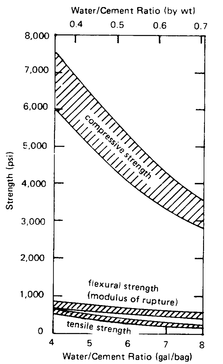
3.1.3.2 Strength. Much of the strength of concrete is
0.80
9.00
related to the amount of mixing water used (W/C ratio).
Thus, the common field practice of adding more water
water is most commonly used; water with a high mineral
to improve workability at a sacrifice in strength should
or salt content, even though it may be called potable,
be avoided. As shown in Figure 3-1, the W/C ratio
may not be suitable.
affects compressive strength much more than tensile
and flexural strengths. Compressive strength increases
3.1.2.4 Admixtures. Admixtures are materials other
with the age of the concrete. The average portland
cement
than cement, aggregate, or water that are added to the
3-2
The lower the curing temperature within this range, the
greater the assurance of proper curing. Too rapid a loss
of water at a higher temperature may result in shrinkage
cracks. When concrete is poured at temperatures
appreciably below 50°F, special heating and/or
insulating techniques must be employed to raise the
temperature to a more favorable level.
3.1.3.3 Durability. A durable concrete will exhibit
resistance to weathering, chemical deterioration, and
erosion. Concrete composition is the most important
factor related to durability. The cement content should
be not less than 8 bags per cubic yard, and the
aggregate/cement ratio not less than 2.6 (by weight).
The durability of concrete exposed to freezing and
thawing is enhanced by use of air-entraining admixtures.
Note that newly poured concrete must not be allowed to
freeze.
3.1.3.4 Watertightness. Excess water in the concrete
mix creates voids or cavities which increase
permeability. Thus, a proper W/C ratio is very important
as is prolonged, thorough curing for watertightness.
However, with an 8-sack mix, one should be able to
obtain a proper W/C ratio 0.45 or less.
3.1.4 SPECIAL CONCRETES FOR WATERFRONT
STRUCTURES
3.1.4.1 Prestressed Concrete. Prestressed concrete is
a special type of reinforced concrete containing
stretched tendons of steel (bars, cables, wire ropes).
The steel is considered pretensioned if it is stretched
before the concrete attains initial set. It is considered
Figure 3-1. Effect of water/cement ratio on 28-day
post-tensioned if it is stretched after the hardened
compressive, flexural, and tensile strengths.
concrete has obtained a specified strength; the
unstretched steel is first encased within ducts to prevent
concrete develops about 75% of its 28-day compressive
its bonding to the concrete. If the concrete was steam-
strength after 7 days. After 1 year it is about 150% of
cured, it will not be equally as durable as a concrete that
the 28-day value, and after 5 years, 200% of this value.
was simply water-cured for the same period of time.
The hardening process begins at final set and continues
indefinitely with favorable curing temperatures. The
favorable temperature range extends from 50° to 90°F.
3-3
3.1.4.2 Fiber-Reinforced Concrete. A new approach
The aggregate should be graded as indicated in Table
to reinforcing concrete is the use of steel fibers, about
0.014 inch in diameter and 1.5 inches long, uniformly
(6)
The formwork in which the concrete is
distributed and randomly directed throughout the
poured must be rigid, carefully fitted, and designed so
concrete mix. Such fibers can be utilized either in
that no underwater currents can pass through it.
ordinary reinforced concrete or prestressed concrete to
Provision must be made for the seawater displaced by
increase the tensile strength and resistance to cracking.
the concrete to escape from within the form. Timber is
generally the most suitable material for construction of
3.1.4.3 Underwater Concrete. Concrete poured
the formwork. Joints between the formwork and the
underwater must have good workability and, thus,
intact portion of a structure should be caulked.
should meet the following conditions:
(7)
Low temperatures during mixing and
(1)
The mixture must incorporate the proper
curing of concrete (i.e., below 50°F) can delay strength
proportions of sand and gravel (preferably not crushed
development for periods as long as one year and so
material) in a rich paste of portland cement and
should be avoided.
freshwater.
(8)
An enclosed chute or "trunk" should be
(2)
The mixing water must not exceed 5.5
specified so that there is no mixing with water during
gallons per bag of cement. (Mixing water includes the
placement.
water entering the batch in the form of free, surface
moisture on the sand and/or gravel; this free water must,
Table 3-2. Gradation of Aggregates for
therefore, be deducted from the total water to be
Tremie Concrete
added.) If the aggregate particles are surface-dry and
Aggregrate
U.S. Standard