Optimizing Subroutines in Assembly Language by Agner Fog - HTML preview
Download the book in PDF, ePub, Kindle for a complete version.
Since there are technological limits to the maximum clock frequency of microprocessors, the trend goes towards increasing processor throughput by handling multiple data in parallel.
When optimizing code, it is important to consider if there are data that can be handled in parallel. The principle of Single-Instruction-Multiple-Data (SIMD) programming is that a vector or set of data are packed together in one large register and handled together in one operation. There are many hundred different SIMD instructions available. These instructions are listed in "IA-32 Intel Architecture Software Developer’s Manual" vol. 2A and 2B, and in "AMD64 Architecture Programmer’s Manual", vol. 4.
Multiple data can be packed into 64-bit MMX registers, 128-bit XMM registers or 256-bit YMM registers in the following ways:
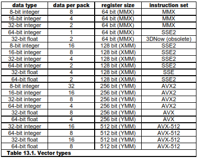
The 64- and 128-bit packing modes are available on all newer microprocessors from Intel, AMD and VIA, except for the obsolete 3DNow mode, which is available only on older AMD processors. The 256-bit vectors are available in Intel Sandy Bridge and AMD Bulldozer. The 512-bit vectors are expected in 2015 or 2016. Whether the different instruction sets are supported on a particular microprocessor can be determined with the CPUID instruction, as explained on page 139. The 64-bit MMX registers cannot be used together with the x87 style floating point registers. The vector registers can only be used if supported by the operating system. See page 140 for how to check if the use of XMM and YMM registers is enabled by the operating system.
It is advantageous to choose the smallest data size that fits the purpose in order to pack as many data as possible into one vector register. Mathematical computations may require double precision (64-bit) floats in order to avoid loss of precision in the intermediate calculations, even if single precision is sufficient for the final result.
Before you choose to use vector instructions, you have to consider whether the resulting code will be faster than the simple instructions without vectors. With vector code, you may spend more instructions on trivial things such as moving data into the right positions in the registers and emulating conditional moves, than on the actual calculations. Example 13.5 below is an example of this. Vector instructions are relatively slow on older processors, but the newest processors can do a vector calculation just as fast as a scalar (single) calculation in many cases.
For floating point calculations, it is often advantageous to use XMM registers rather than x87 registers, even if there are no opportunities for handling data in parallel. The XMM registers are handled in a more straightforward way than the old x87 register stack.
Memory operands for XMM instructions without VEX prefix have to be aligned by 16. Memory operands for YMM instructions are preferably aligned by 32 and ZMM by 64, but not necessarily. See page 86 for how to align data in memory.
Most common arithmetic and logical operations can be performed in vector registers. The following example illustrates the addition of two arrays:
; Example 13.1a. Adding two arrays using vectors
; float a[100], b[100], c[100];
; for (int i = 0; i < 100; i++) a[i] = b[i] + c[i];
; Assume that a, b and c are aligned by 16
xor ecx, ecx ; Loop counter i
L: movaps xmm0, b[ecx] ; Load 4 elements from b
addps xmm0, c[ecx] ; Add 4 elements from c
movaps a[ecx], xmm0 ; Store result in a
add ecx, 16 ; 4 elements * 4 bytes = 16
cmp ecx, 400 ; 100 elements * 4 bytes = 400
jb L ; Loop
There are no instructions for integer division. Integer division by a constant divisor can be implemented as multiplication and shift, using the method described on page 144 or the functions in the library at www.agner.org/optimize/asmlib.zip.
13.1 Conditional moves in SIMD registers
Consider this C++ code which finds the biggest values in four pairs of values:
// Example 13.2a. Loop to find maximums
float a[4], b[4], c[4];
for (int i = 0; i < 4; i++) {
c[i] = a[i] > b[i] ? a[i] : b[i];
}
If we want to implement this code with XMM registers then we cannot use a conditional jump for the branch inside the loop because the branch condition is not the same for all four elements. Fortunately, there is a maximum instruction that does the same:
; Example 13.2b. Maximum in XMM
movaps xmm0, [a] ; Load a vector
maxps xmm0, [b] ; max(a,b)
movaps [c], xmm0 ; c = a > b ? a : b
Minimum and maximum vector instructions exist for single and double precision floats and for 8-bit and 16-bit integers. The absolute value of floating point vector elements is calculated by AND'ing out the sign bit, as shown in example 13.8 page 126. Instructions for the absolute value of integer vector elements exist in the "Supplementary SSE3" instruction set. The integer saturated addition vector instructions (e.g. PADDSW) can also be used for finding maximum or minimum or for limiting values to a specific range.
These methods are not very general, however. The most general way of doing conditional moves in vector registers is to use Boolean vector instructions. The following example is a modification of the above example where we cannot use the MAXPS instruction:
// Example 13.3a. Branch in loop
float a[4], b[4], c[4], x[4], y[4];
for (int i = 0; i < 4; i++) {
c[i] = x[i] > y[i] ? a[i] : b[i];
}
The necessary conditional move is done by making a mask that consists of all 1's when the condition is true and all 0's when the condition is false. a[i] is AND'ed with this mask and b[i] is AND'ed with the inverted mask:
; Example 13.3b. Conditional move in XMM registers
movaps xmm1, [y] ; Load y vector
cmpltps xmm1, [x] ; Compare with x. xmm1 = mask for y < x
movaps xmm0, [a] ; Load a vector
andps xmm0, xmm1 ; a AND mask
andnps xmm1, [b] ; b AND NOT mask
orps xmm0, xmm1 ; (a AND mask) OR (b AND NOT mask)
movaps [c], xmm0 ; c = x > y ? a : b
The vectors that make the condition (x and y in example 13.3b) and the vectors that are selected (a and b in example 13.3b) need not be the same type. For example, x and y could be integers. But they should have the same number of elements per vector. If a and b are double's with two elements per vector, and x and y are 32-bit integers with four elements per vector, then we have to duplicate each element in x and y in order to get the right size of the mask (See example 13.5b below).
Note that the AND-NOT instruction (andnps, andnpd, pandn) inverts the destination operand, not the source operand. This means that it destroys the mask. Therefore we must have andps before andnps in example 13.3b. If SSE4.1 is supported then we can use the BLENDVPS instruction instead:
; Example 13.3c. Conditional move in XMM registers, using SSE4.1
movaps xmm0, [y] ; Load y vector
cmpltps xmm0, [x] ; Compare with x. xmm0 = mask for y < x
movaps xmm1, [a] ; Load a vector
blendvps xmm1, [b], xmm0 ; Blend a and b
movaps [c], xmm0 ; c = x > y ? a : b
If the mask is needed more than once then it may be more efficient to AND the mask with an XOR combination of a and b. This is illustrated in the next example which makes a conditional swapping of a and b:
// Example 13.4a. Conditional swapping in loop
float a[4], b[4], x[4], y[4], temp;
for (int i = 0; i < 4; i++) {
if (x[i] > y[i]) {
temp = a[i]; // Swap a[i] and b[i] if x[i] > y[i]
a[i] = b[i];
b[i] = temp;
}
}
And now the assembly code using XMM vectors:
; Example 13.4b. Conditional swapping in XMM registers, SSE
movaps xmm2, [y] ; Load y vector
cmpltps xmm2, [x] ; Compare with x. xmm2 = mask for y < x
movaps xmm0, [a] ; Load a vector
movaps xmm1, [b] ; Load b vector
xorps xmm0, xmm1 ; a XOR b
andps xmm2, xmm0 ; (a XOR b) AND mask
xorps xmm1, xmm2 ; b XOR ((a XOR b) AND mask)
xorps xmm2, [a] ; a XOR ((a XOR b) AND mask)
movaps [b], xmm1 ; (x[i] > y[i]) ? a[i] : b[i]
movaps [a], xmm2 ; (x[i] > y[i]) ? b[i] : a[i]
The xorps xmm0,xmm1 instruction generates a pattern of the bits that differ between a and b. This bit pattern is AND'ed with the mask so that xmm2 contains the bits that need to be changed if a and b should be swapped, and zeroes if they should not be swapped. The last two xorps instructions flip the bits that have to be changed if a and b should be swapped and leave the values unchanged if not.
The mask used for conditional moves can also be generated by copying the sign bit into all bit positions using the arithmetic shift right instruction psrad. This is illustrated in the next example where vector elements are raised to different integer powers. We are using the method in example 12.14a page 114 for calculating powers.
// Example 13.5a. Raise vector elements to different integer powers
double x[2], y[2]; unsigned int n[2];
for (int i = 0; i < 2; i++) {
y[i] = pow(x[i],n[i]);
}
If the elements of n are equal then the simplest solution is to use a branch. But if the powers are different then we have to use conditional moves:
; Example 13.5b. Raise vector to power, using integer mask, SSE2
.data ; Data segment
align 16 ; Must be aligned
ONE DQ 1.0, 1.0 ; Make constant 1.0
X DQ ?, ? ; x[0], x[1]
Y DQ ?, ? ; y[0], y[1]
N DD ?, ? ; n[0], n[1]
.code
; register use:
; xmm0 = xp
; xmm1 = power
; xmm2 = i (i0 and i1 each stored twice as DWORD integers)
; xmm3 = 1.0 if not(i & 1)
; xmm4 = xp if (i & 1)
movq xmm2, [N] ; Load n0, n1
punpckldq xmm2, xmm2 ; Copy to get n0, n0, n1, n1
movapd xmm0, [X] ; Load x0, x1
movapd xmm1, [one] ; power initialized to 1.0
mov eax, [N] ; n0
or eax, [N+4] ; n0 OR n1 to get highest significant bit
xor ecx, ecx ; 0 if n0 and n1 are both zero
bsr ecx, eax ; Compute repeat count for max(n0,n1)
L1: movdqa xmm3, xmm2 ; Copy i
pslld xmm3, 31 ; Get least significant bit of i
psrad xmm3, 31 ; Copy to all bit positions to make mask
psrld xmm2, 1 ; i >>= 1
movapd xmm4, xmm0 ; Copy of xp
andpd xmm4, xmm3 ; xp if bit = 1
andnpd xmm3, [one] ; 1.0 if bit = 0
orpd xmm3, xmm4 ; (i & 1) ? xp : 1.0
mulpd xmm1, xmm3 ; power *= (i & 1) ? xp : 1.0
mulpd xmm0, xmm0 ; xp *= xp
sub ecx, 1 ; Loop counter
jns L1 ; Repeat ecx+1 times
movapd [Y], xmm1 ; Store result
The repeat count of the loop is calculated separately outside the loop in order to reduce the number of instructions inside the loop.
Timing analysis for example 13.5b in P4E: There are four continued dependency chains: xmm0: 7 clocks, xmm1: 7 clocks, xmm2: 4 clocks, ecx: 1 clock. Throughput for the different execution units: MMX-SHIFT: 3 µops, 6 clocks. MMX-ALU: 3 µops, 6 clocks. FP-MUL: 2 µops, 4 clocks. Throughput for port 1: 8 µops, 8 clocks. Thus, the loop appears to be limited by port 1 throughput. The best timing we can hope for is 8 clocks per iteration which is the number of µops that must go to port 1. However, three of the continued dependency chains are interconnected by two broken, but quite long, dependency chains involving xmm3 and xmm4, which take 23 and 19 clocks, respectively. This tends to hinder the optimal reordering of µops. The measured time is approximately 10 µops per iteration. This timing actually requires a quite impressive reordering capability, considering that several iterations must be overlapped and several dependency chains interwoven in order to satisfy the restrictions on all ports and execution units.
Conditional moves in general purpose registers using CMOVcc and floating point registers using FCMOVcc are no faster than in XMM registers.
On processors with the SSE4.1 instruction set we can use the PBLENDVB, BLENDVPS or BLENDVPD instructions instead of the AND/OR operations as in example 13.3c above. On AMD processors with the XOP instruction set we may alternatively use the VPCMOV instruction in the same way.
13.2 Using vector instructions with other types of data than they are intended for
Most XMM, YMM and ZMM instructions are 'typed' in the sense that they are intended for a particular type of data. For example, it doesn't make sense to use an instruction for adding integers on floating point data. But instructions that only move data around will work with any type of data even though they are intended for one particular type of data. This can be useful if an equivalent instruction doesn't exist for the type of data you have or if an instruction for another type of data is more efficient.
All vector instructions that move, shuffle, blend or shift data as well as the Boolean instructions can be used for other types of data than they are intended for. But instructions that do any kind of arithmetic operation, type conversion or precision conversion can only be used for the type of data it is intended for. For example, the FLD instruction does more than move floating point data, it also converts