Optimizing Subroutines in Assembly Language by Agner Fog - HTML preview
Download the book in PDF, ePub, Kindle for a complete version.
Reading from the level-1 cache takes approximately 3 clock cycles. Reading from the level- 2 cache takes in the order of magnitude of 10 clock cycles. Reading from main memory takes in the order of magnitude of 100 clock cycles. The access time is even longer if a DRAM page boundary is crossed, and extremely long if the memory area has been swapped to disk. I cannot give exact access times here because it depends on the hardware configuration and the figures keep changing thanks to the fast technological development.
However, it is obvious from these numbers that caching of code and data is extremely important for performance. If the code has many cache misses, and each cache miss costs more than a hundred clock cycles, then this can be a very serious bottleneck for the performance.
More advice on how to organize data for optimal caching are given in manual 1: "Optimizing software in C++". Processor-specific details are given in manual 3: "The microarchitecture of Intel, AMD and VIA CPUs" and in Intel's and AMD's software optimization manuals.
A cache is a means of temporary storage that is closer to the microprocessor than the main memory. Data and code that is used often, or that is expected to be used soon, is stored in a cache so that it is accessed faster. Different microprocessors have one, two or three levels of cache. The level-1 cache is close to the microprocessor kernel and is accessed in just a few clock cycles. A bigger level-2 cache is placed on the same chip or at least in the same housing.
The level-1 data cache in the P4 processor, for example, can contain 8 kb of data. It is organized as 128 lines of 64 bytes each. The cache is 4-way set-associative. This means that the data from a particular memory address cannot be assigned to an arbitrary cache line, but only to one of four possible lines. The line length in this example is 26 = 64. So each line must be aligned to an address divisible by 64. The least significant 6 bits, i.e. bit 0 - 5, of the memory address are used for addressing a byte within the 64 bytes of the cache line. As each set comprises 4 lines, there will be 128 / 4 = 32 = 25 different sets. The next five bits, i.e. bits 6 - 10, of a memory address will therefore select between these 32 sets. The remaining bits can have any value. The conclusion of this mathematical exercise is that if bits 6 - 10 of two memory addresses are equal, then they will be cached in the same set of cache lines. The 64-byte memory blocks that contend for the same set of cache lines are spaced 211 = 2048 bytes apart. No more than 4 such addresses can be cached at the same time.
Let me illustrate this by the following piece of code, where EDI holds an address divisible by 64:
; Example 11.1. Level-1 cache contention
again: mov eax, [edi]
mov ebx, [edi + 0804h]
mov ecx, [edi + 1000h]
mov edx, [edi + 5008h]
mov esi, [edi + 583ch]
sub ebp, 1
jnz again
The five addresses used here all have the same set-value because the differences between the addresses with the lower 6 bits truncated are multiples of 2048 = 800H. This loop will perform poorly because at the time we read ESI, there is no free cache line with the proper set-value, so the processor takes the least recently used of the four possible cache lines - that is the one which was used for EAX - and fills it with the data from [EDI+5800H] to [EDI+583FH] and reads ESI. Next, when reading EAX, we find that the cache line that held the value for EAX has now been discarded, so the processor takes the least recently used line, which is the one holding the EBX value, and so on. We have nothing but cache misses, but if the 5'th line is changed to MOV ESI,[EDI + 5840H] then we have crossed a 64 byte boundary, so that we do not have the same set-value as in the first four lines, and there will be no problem assigning a cache line to each of the five addresses.
The cache sizes, cache line sizes, and set associativity on different microprocessors are described in manual 3: "The microarchitecture of Intel, AMD and VIA CPUs". The performance penalty for level-1 cache line contention can be quite considerable on older microprocessors, but on newer processors such as the P4 we are losing only a few clock cycles because the data are likely to be prefetched from the level-2 cache, which is accessed quite fast through a full-speed 256 bit data bus. The improved efficiency of the level-2 cache in the P4 compensates for the smaller level-1 data cache.
The cache lines are always aligned to physical addresses divisible by the cache line size (in the above example 64). When we have read a byte at an address divisible by 64, then the next 63 bytes will be cached as well, and can be read or written to at almost no extra cost. We can take advantage of this by arranging data items that are used near each other together into aligned blocks of 64 bytes of memory.
The level-1 code cache works in the same way as the data cache, except on processors with a trace cache (see below). The level-2 cache is usually shared between code and data.
The Intel P4 and P4E processors have a trace cache instead of a code cache. The trace cache stores the code after it has been translated to micro-operations (µops) while a normal code cache stores the raw code without translation. The trace cache removes the bottleneck of instruction decoding and attempts to store the code in the order in which it is executed rather than the order in which it occurs in memory. The main disadvantage of a trace cache is that the code takes more space in a trace cache than in a code cache. Later Intel processors do not have a trace cache.
The Intel Sandy Bridge and later processors have a traditional code cache before the decoders and a µop cache after the decoders. The µop cache is a big advantage because instruction decoding is often a bottleneck on Intel processors. The capacity of the µop cache is much smaller than the capacity of the level-1 code cache. The µop cache is such a critical resource that the programmer should economize its use and make sure the critical part of the code fits into the µop cache. One way to economize trace cache use is to avoid loop unrolling.
Most AMD processors have instruction boundaries marked in the code cache. This relieves the critical bottleneck of instruction length decoding and can therefore be seen as an alternative to a µop cache. I do not know why this technique is not used in current Intel processors.
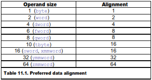
All data in RAM should be aligned at addresses divisible by a power of 2 according to this scheme:
The following example illustrates alignment of static data.
; Example 11.2, alignment of static data
.data
A DQ ?, ? ; A is aligned by 16
B DB 32 DUP (?)
C DD ?
D DW ?
ALIGN 16 ; E must be aligned by 16
E DQ ?, ?
.code
movdqa xmm0, [A]
movdqa [E], xmm0
In the above example, A, B and C all start at addresses divisible by 16. D starts at an address divisible by 4, which is more than sufficient because it only needs to be aligned by 2. An alignment directive must be inserted before E because the address after D is not divisible by 16 as required by the MOVDQA instruction. Alternatively, E could be placed after A or B to make it aligned.
Most microprocessors have a penalty of several clock cycles when accessing misaligned data that cross a cache line boundary. AMD K8 and earlier processors also have a penalty when misaligned data cross an 8-byte boundary, and some early Intel processors (P1, PMMX) have a penalty for misaligned data crossing a 4-byte boundary. Most processors have a penalty when reading a misaligned operand shortly after writing to the same operand.
Most XMM instructions that read or write 16-byte memory operands require that the operand is aligned by 16. Instructions that accept unaligned 16-byte operands can be quite inefficient on older processors. However, this restriction is largely relieved with the AVX instruction set. AVX instructions do not require alignment of memory operands, except for the explicitly aligned instructions. Processors that support the AVX instruction set generally handle misaligned memory operands very efficiently.
Aligning data stored on the stack can be done by rounding down the value of the stack pointer. The old value of the stack pointer must of course be restored before returning. A function with aligned local data may look like this:
; Example 11.3a, Explicit alignment of stack (32-bit Windows)
_FuncWithAlign PROC NEAR
push ebp ; Prolog code
mov ebp, esp ; Save value of stack pointer
sub esp, LocalSpace ; Allocate space for local data
and esp, 0FFFFFFF0H ; (= -16) Align ESP by 16
mov eax, [ebp+8] ; Function parameter = array
movdqu xmm0,[eax] ; Load from unaligned array
movdqa [esp],xmm0 ; Store in aligned space
call SomeOtherFunction ; Call some other function
...
mov esp, ebp ; Epilog code. Restore esp
pop ebp ; Restore ebp
ret
_FuncWithAlign ENDP
This function uses EBP to address function parameters, and ESP to address aligned local data. ESP is rounded down to the nearest value divisible by 16 simply by AND'ing it with -16. You can align the stack by any power of 2 by AND'ing the stack pointer with the negative value.
All 64-bit operating systems, and some 32-bit operating systems (Mac OS, optional in Linux) keep the stack aligned by 16 at all CALL instructions. This eliminates the need for the AND instruction and the frame pointer. It is necessary to propagate this alignment from one CALL instruction to the next by proper adjustment of the stack pointer in each function:
; Example 11.3b, Propagate stack alignment (32-bit Linux)
FuncWithAlign PROC NEAR
sub esp, 28 ; Allocate space for local data
mov eax, [esp+32] ; Function parameter = array
movdqu xmm0,[eax] ; Load from unaligned array
movdqa [esp],xmm0 ; Store in aligned space
call SomeOtherFunction ; This call must be aligned
...
ret
FuncWithAlign ENDP
In example 11.3b we are relying on the fact that the stack pointer is aligned by 16 before the call to FuncWithAlign. The CALL FuncWithAlign instruction (not shown here) has pushed the return address on the stack, whereby 4 is subtracted from the stack pointer. We have to subtract another 12 from the stack pointer before it is aligned by 16 again. The 12 is not enough for the local variable that needs 16 bytes so we have to subtract 28 to keep the stack pointer aligned by 16. 4 for the return address + 28 = 32, which is divisible by 16. Remember to include any PUSH instructions in the calculation. If, for example, there had been one PUSH instruction in the function prolog then we would subtract 24 from ESP to keep it aligned by 16. Example 11.3b needs to align the stack for two reasons. The MOVDQA instruction needs an aligned operand, and the CALL SomeOtherFunction needs to be aligned in order to propagate the correct stack alignment to SomeOtherFunction.
The principle is the same in 64-bit mode:
; Example 11.3c, Propagate stack alignment (64-bit Linux)
FuncWithAlign PROC
sub rsp, 24 ; Allocate space for local data
mov rax, rdi ; Function parameter rdi = array
movdqu xmm0,[rax] ; Load from unaligned array
movdqa [rsp],xmm0 ; Store in aligned space
call SomeOtherFunction ; This call must be aligned
...
ret
FuncWithAlign ENDP
Here, the return address takes 8 bytes and we subtract 24 from RSP, so that the total amount subtracted is 8 + 24 = 32, which is divisible by 16. Every PUSH instruction subtracts 8 from RSP in 64-bit mode.
Alignment issues are also important when mixing C++ and assembly language. Consider this C++ structure:
// Example 11.4a, C++ structure
struct abcd {
unsigned char a; // takes 1 byte storage
int b; // 4 bytes storage
short int c; // 2 bytes storage
double d; // 8 bytes storage
} x;
Most compilers (but not all) will insert three empty bytes between a and b, and six empty bytes between c and d in order to give each element its natural alignment. You may change the structure definition to:
// Example 11.4b, C++ structure
struct abcd {
double d; // 8 bytes storage
int b; // 4 bytes storage
short int c; // 2 bytes storage
unsigned char a; // 1 byte storage
char unused[1]; // fill up to 16 bytes
} x;
This has several advantages: The implementation is identical on compilers with and without automatic alignment, the structure is easily translated to assembly, all members are properly aligned, and there are fewer unused bytes. The extra unused character in the end makes sure that all elements in an array of structures are properly aligned.
See page 160 for how to move unaligned blocks of data efficiently.
Most microprocessors fetch code in aligned 16-byte or 32-byte blocks. If an important subroutine entry or jump label happens to be near the end of a 16-byte block then the microprocessor will only get a few useful bytes of code when fetching that block of code. It may have to fetch the next 16 bytes too before it can decode the first instructions after the label. This can be avoided by aligning important subroutine entries and loop entries by 16. Aligning by 8 will assure that at least 8 bytes of code can be loaded with the first instruction fetch, which may be sufficient if the instructions are small. We may align subroutine entries by the cache line size (typically 64 bytes) if the subroutine is part of a critical hot spot and the preceding code is unlikely to be executed in the same context.
A disadvantage of code alignment is that some cache space is lost to empty spaces before the aligned code entries.
In most cases, the effect of code alignment is minimal. So my recommendation is to align code only in the most critical cases like critical subroutines and critical innermost loops.
Aligning a subroutine entry is as simple as putting as many NOP's as needed before the subroutine entry to make the address divisible by 8, 16, 32 or 64, as desired. The assembler does this with the ALIGN directive. The NOP's that are