Java 3D Programming by Daniel Selman - HTML preview
Download the book in PDF, ePub, Kindle for a complete version.
The scenegraph
4.3 Java 3D and the scenegraph
4.4 Elements of scenegraph design
4.7 Immediate mode vs. retained mode vs. mixed mode
Is a scenegraph appropriate for your application? If you choose to use a scenegraph for your application you should be able to sketch the required elements out on paper.
In this chapter, I’ll introduce the concept of a scenegraph for modeling 3D scenes. I’ll present several examples that can be used to guide the scenegraph design process for your application. I’ll show you the benefits and drawbacks of using the Java 3D scenegraph along with comparative information for rendering in immediate mode and mixed mode. The possible elements of a Java 3D scenegraph are presented along with usage hints and tips.
Your application’s 3D virtual world contains geometric objects with which the user interacts. In Java 3D this virtual world is called the VirtualUniverse, the top-level class that contains all the elements that you define within your virtual world. In addition, the VirtualUniverse contains nongeometric objects that control or influence the world. Lights are a good example of this type of object. In a 3D environment, one cannot see a Light, but one can see the effect of the Light within its zone of influence.
A concrete example helps to describe some of the details. Imagine a virtual world that models a Formula 1 Grand Prix race (figure 4.1). The model is a simplification of reality. It contains:
- 3 Williams F1 cars
- 2 Ferrari F1 cars
- 3 McLaren F1 cars
- 2 Jordan F1 cars
- 1,000 trees
300 pine
300 oak
400 spruce
- 100 pit crew
- 100 marshals
- 60 advertising billboards
20 for a sport channel
20 for a car part manufacturer
20 for a cigarette manufacturer
- 200 straw bales
- 1 racing circuit
- 1 start light
- 1 grass area upon which the race track is situated
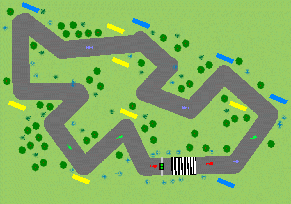
Figure 4.1 An overhead view of our example virtual world—the prototypical race circuit
Taking a quick sum of the elements we see there are 1,473 objects in this VirtualUniverse. However, there are only 16 different types of objects. So, if you had the luxury of a team of 3D graphics artists and modelers, you could send the list away and a few weeks later receive 16 VRML format (for example) 3D graphics files. In fact, one might even define classes and subclasses, breaking the objects into cars, trees, people, billboards, bales, start light, racing circuit, and grass and hence require only eight classes. In this case the 3D graphics artists will produce a single F1 racecar model that can be customized (using color for example) to create the three subclasses McLaren, Williams, and Ferrari.
You should now be wondering how, with 1,473 distinct objects in your scenegraph and only eight classes of objects, you can organize the objects in your world so that you minimize memory overhead and rendering time but maximize programming flexibility.
You should also be aware that some of the objects within the world are dynamic:
- F1 cars
- Pit crew and marshals
Some of the objects are static:
- Straw bales
- Trees
- Billboards
- Race track
- Start light
- Grass
It is important to note in this context that “static” means “does not move relative to the circuit,” or “does not move relative to the grass area upon which the circuit sits.” It does not mean that the items are static relative to the center of the universe or even (potentially) relative to the center of the Earth.
So, static and dynamic in this example have defined movement relationships between the items listed and the circuit. You should also therefore think about the spatial relationships between a class of items and all other classes of items. For example, the circuit never moves relative to the grass and maybe the straw bales are always situated 25 meters in front of a billboard; or you model groups of trees in which there was a fixed spatial relationship between the trees within each group.
Some of the objects have appearances that change:
- Dynamically
Start light (red to green)
- Statically
F1 cars (Williams, McLaren, or Ferrari insignia)
People (either pit crew or marshal uniforms)
Trees (pine, oak, or spruce graphic)
Assume that you are using a low-level graphics API that can only render triangles, points, and lines at a given x, y, z coordinate.
Your primitive rendering loop might look like:
1. Run some control logic.
2. Update the x, y, z position of dynamic triangles.
3. Update the appearance of triangles whose appearance changes dynamically.
4. Draw the triangles.
5. Go to next frame.
It should be obvious that this approach does not exploit much of the information about the structure of the world that you developed initially. The rendering API has no concept of an object and it has no concept of spatial (or otherwise) relationships between objects. This is analogous to sending your initial list of 1,473 objects to the graphics artists and making them do all the work.
What you need is a data structure that you can use both to describe the relationships between objects and exploit to optimize your rendering and memory requirements. Read on.
A scenegraph is a hierarchical data structure that captures the elements of spatial relationships between objects. Technically a scenegraph is a directed acyclic graph (DAG). Once you think and model an application hierarchically, the 3D graphics API is provided with a much richer set of information to use to optimize rendering. A scenegraph description also enables application developers to apply object-orientated (OO) principles such as abstraction and reuse to their designs.
In Java 3D, the scenegraph is encapsulated within the VirtualUniverse class. The scenegraph is composed of objects derived from the Node class. Every instance of the Node class has one parent Node. Additionally, the scenegraph contains objects derived from the Group class which encapsulates a collection of Node child objects. In this way a hierarchy of Group-derived objects can be created with Node-derived objects attached to the parent Group objects, as shown in figure 4.2.
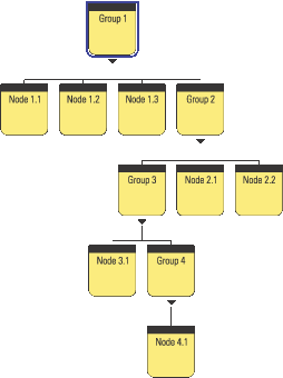
Figure 4.2 Four Groups with child Nodes. The parent-child relationships allow you to build a scenegraph hierarchy. Note that cycles are not permitted (e.g., Group 3 cannot also have Node 1.1 as a child); hence the scenegraph is a DAG
There are three basic classes of objects within the scenegraph:
- Management nodes—Locale, BranchGroup, TransformGroup, ViewPlatform, Switch, and so forth. These are predominantly derived from Group and manage a collection of child objects.
- Geometry nodes—Shape3D, Background, and so forth. These objects are derived from Leaf and define visible geometry within the application’s virtual world.
- Control or influence nodes—Behaviors, Morph, Light, Sound, Clip, and so forth. These define application behavior and are typically not directly related to the geometry used within the application.
BranchGroup and TransformGroup are both Group nodes (i.e., they can contain child Nodes). A TransformGroup also contains translation, scaling, and rotation information that it applied to its child Nodes. The details of the nodes available in Java 3D are presented in later chapters.
For example, consider how one might compose the scenegraph for the F1 car. The car can be roughly anatomized into seven parts (figure 4.3): four wheels, chassis, rear fin, and front stabilizer.
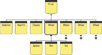
Figure 4.3 Sample scenegraph for the F1 car, plus icons represent unexpanded Groups
Each wheel is composed of spokes, a rim, and a tire. In this way the branch of the scenegraph that defines a wheel—that is, the Wheel Group and its three child Nodes, can be reused and duplicated to create the four wheels required for the F1 car.
The scenegraph also encodes a spatial relationship. When the F1 car is moved, its child Nodes are automatically also moved. For example, the stabilizer might be positioned three meters from the origin of the F1 car in the x direction—this spatial relationship will be preserved irrespective of the position of the F1 car’s origin. If the wheel is rotated about its axis, the spokes, rim and tire will all be automatically rotated.
The scenegraph allows model complexity to be selectively specified. Just as you have chosen to create the Wheel from three subcomponents, you might choose to further decompose the chassis to introduce more detail into the model. You might have the opportunity to reuse scenegraph branches—perhaps other classes of vehicles at the race circuit require tires that are similar to the F1 tires? Perhaps you need to create piles of tires in the pit?
Various 3D graphics file formats (e.g., VRML) allow models to be created that are composed from subcomponents.
Figure 4.4 shows how the F1 car fits into the overall scenegraph for the F1 racing application.
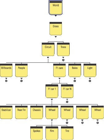
Figure 4.4 Sample scenegraph for the F1 race track application
This scenegraph shown in figure 4.4 embodies the following relationships:
- Moving the grass area upon which the racing circuit sits will also move the circuit and the trees around it.
- Moving the circuit will move the advertising billboards, people at the circuit, cars on the circuit, straw bales, and the start light.
- Moving a F1 car moves its component parts: stabilizer, rear fin, chassis, and wheels.
- Rotating an F1 car’s wheels will rotate the wheel’s spokes, rim, and tire.
By designing the scenegraph with the spatial relationships in mind, scenegraph elements can be easily reused. Perhaps in the future the racetrack application will be expanded to contain two circuits with an animated transition sequence between them. The transition sequence will use a view from a helicopter flying between the circuits.
You’ll need to reuse the circuit scenegraph branch and introduce a new element for the helicopter. Figure 4.5 shows how these elements might be introduced into the original scenegraph.
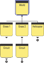
Figure 4.5 Adding a new circuit and a helicopter to the scenegraph
This formulation reuses the whole circuit branch of the scenegraph. The new circuit will have its own surrounding terrain and trees, as well as all the circuit geometry. You’ll need to move the helicopter independently of the grass for each circuit, so the helicopter Group is added directly into the world Group. Moving the world will move the two circuits as well as the helicopter.
4.3 Java 3D and the scenegraph
This section will cover additional scenegraph elements required by Java 3D to manage and render your scenegraph.
A VirtualUniverse contains at least one Locale object. A Locale defines a geographical region within your scenegraph. Locales are covered in depth in chapter 6.
In Java 3D there are two distinct branches within the scenegraph: scene and view. Up to now we have discussed only the high-level principles behind the scene side of the scenegraph. The scene branch contains the application’s scenegraph elements, as discussed in the preceding examples. The view branch contains a ViewPlatform node and defines scaling, rotation, and translation information for the view. The view is responsible for rendering the scene side of the scenegraph. As shown in figure 4.6, the view attaches to a ViewPlatform and reads position and orientation information from the Nodes above the ViewPlatform on the view side of the scenegraph.
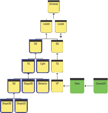
Figure 4.6 Example Java 3D scenegraph. BG: BranchGroup, TG: TransformGroup, VP: ViewPlatform. The scene side of the scenegraph has been highlighted (the left branch of the Locale). The right branch of the Locale is the view side of the scenegraph
The view renders into its attached Canvas3D component. Canvas3D is a GUI component with an associated native windowing system window.
It is possible to have multiple ViewPlatforms in a scenegraph. Multiple ViewPlatforms allow you to define multiple points of view of your scene. By removing the view from a ViewPlatform and attaching it to a new ViewPlatform you can easily shift between predefined points of view.
It is also possible to have multiple views each rendering into multiple Canvas3Ds. For more on these advanced scenegraph features please refer to chapter 6.
An important property of a Node in the scenegraph is that it contains boundary (Bounds is the Java 3D class) information for the Node. The Bounds instance is typically a BoundingSphere or a BoundingBox object. These classes (derived from Bounds) define a volume of space within the 3D scene that encloses all the geometry and children of the Node. For the F1 car example this would mean that the Bounds for the F1 car Group node are such that they enclose the geometry for the stabilizer, rear fin, chassis, and four wheel Nodes. In turn, the Bounds for the wheel Group Node are such that they enclose the geometry for the spokes, rim, and tire Nodes.
Java 3D can exploit the hierarchical Bounds information to optimize many scenegraph operations, including rendering. For example, when the Renderer comes to render an F1 car, if it finds that the Bounds of the F1 car Group are outside the current view frustum the Renderer can immediately move on to the next car in the scene. The high-level visibility test on the F1 car Group has saved the Renderer from performing visibility tests on the child Nodes of the F1 car Group.
This implies another important property of a good scenegraph hierarchy: the structure of the scenegraph should provide as much Bounds information as possible to allow the Renderer to optimize rendering. As the scenegraph designer you should be cognizant of the potential Bounds of your scenegraph Nodes. From the full F1 race circuit example you could see that as you move down the scenegraph hierarchy the Bounds of the Groups and Nodes become smaller and smaller.
The Grass Group contains everything within the 3D scene, and as such must always be recursively processed by the Renderer. The Grass Group will be rendered irrespective of the user’s point of view of the scene. It would not matter whether the user was riding in-car with a point of view from one of drivers, was orbiting the circuit in a helicopter, or had a view from somewhere around the circuit. If the user can see the virtual world, the Renderer will process the grass Group. Figure 4.7 shows three sample points of view around the circuit.
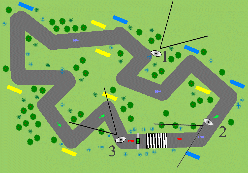
Figure 4.7 The Bounds for the Grass Group enclose everything within the 3D scene. Three FOVs have been defined:
#1 is a Marshal’s view, #2 is a McLaren driver’s view, #3 is a Ferrari driver’s view
The trees Group (figure 4.8) contains all the trees within the scene. Since the trees are scattered across the terrain surrounding the race circuit the trees Group will have Bounds that are close to the size of the grass Group. The trees Group will also usually be processed by the scenegraph Renderer (as most points of view around the circuit will intersect trees). Conceivably the viewer of the scene could be positioned at the periphery of the circuit and facing away from the center of the circuit, such that their FOV falls outside of the Bounds of the trees Group. Note that FOV #1 is not such a case. Though viewer #1 cannot see any trees, his FOV does intersect the trees Group’s Bounds object. Each of the trees within the Trees Group will have to be tested against FOV #1—even though none of them actually intersect with FOV #1.
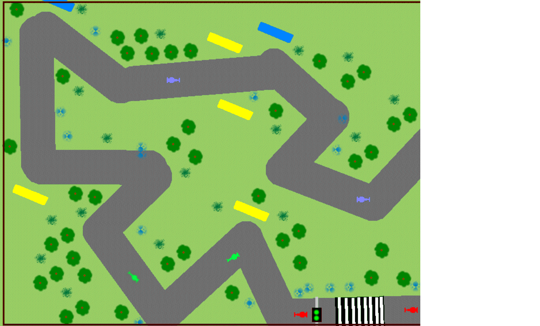
Figure 4.8 The Bounds for the trees enclose all the trees within the 3D scene
The Circuit Group (figure 4.9) encloses all of the geometry that composes the circuit roadway. This is still a large Group and not significantly smaller than the overall grass Group. It is very unlikely that a viewer of the scene will not be able to view the circuit, which is the central feature of the application.
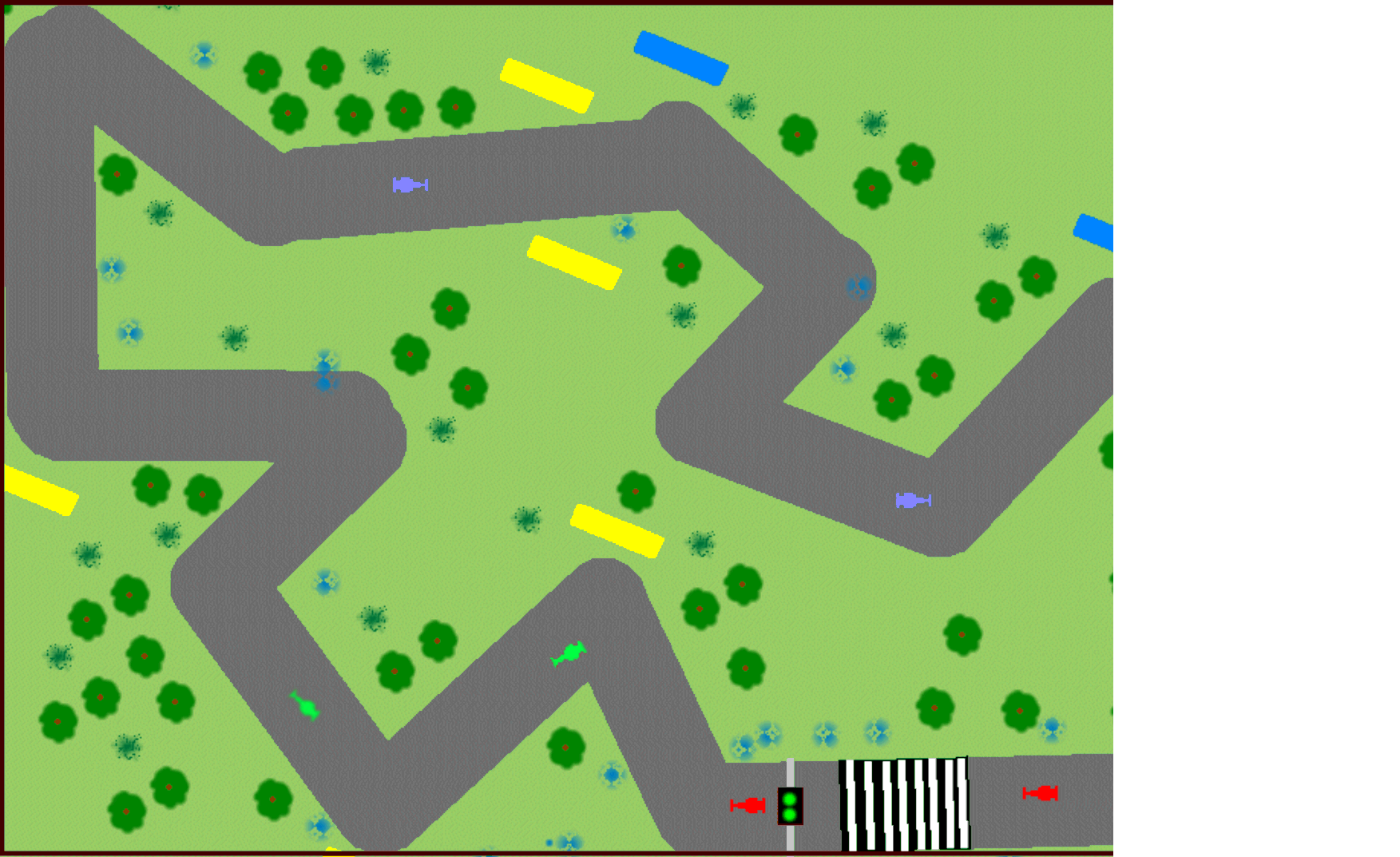
Figure 4.9 The Bounds for the Circuit Group encloses the racing circuit
The F1 car Group (figure 4.10), on the other hand, merely has Bounds that enclose the geometry required for an individual F1 car (a meter by a few meters). It is very likely that a particular F1 car Group will not intersect a given FOV. It is highly unlikely that a single viewer will be able to see all of the F1 cars as they race around the circuit. For example
- FOV #1 intersects with 0 F1 car Groups
- FOV #2 intersects with 1 F1 car Group
- FOV #3 intersects with 1 F1 car Group

Figure 4.10 The Bounds for the F1 car Group encloses the child Nodes that define the geometry for the F1 car
As there are 10 F1 car Groups in the scenegraph this represents a considerable saving.
The start light Group (figure 4.11) will be even smaller than the F1 car Group (less than a cubic meter). It will rarely intersect with a given FOV, even if we ride in the car with a driver. None of the FOVs defined on figure 4.7 can see the start light.
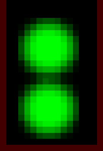
Figure 4.11 The Bounds for the start light Group encloses just the child Nodes that define the geometry for the start light
Figure 4.12 shows bounding rectangles for five classes of objects in the racing circuit virtual world. The level of detail of objects within the world should reflect the theme of the application. For example, the grass around the circuit would probably be modeled as a simple rectangular height field with an applied texture image, while the F1 cars themselves would be complex 3D models composed from hundreds of vertices. On the other hand, if the application were a landscape design package the grass and trees may be represented using complex geometry. Some of the most challenging applications allow the user to control the application at several levels of detail, dynamically reapportioning the detail within the scene as appropriate. An excellent example of this is the game “Black and White” by Lionhead. The game allows the user to zoom out to control entire countries and to zoom in to view individual character animations and interactions.
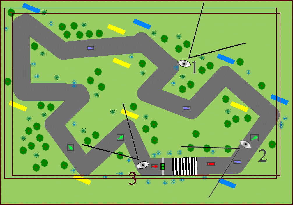
Figure 4.12 Some of the overall Bounds for the scene. Illustrated are Grass, Trees, Circuit, F1 cars, and Start Light. See figure 4.7 for the FOV
4.4 Elements of scenegraph design
Designing a good scenegraph structure may involve making trade-offs across several factors. The scenegraph should be easy to manipulate at runtime (you may want to dynamically attach and detach entire branches to switch them on or off) as well as easy to customize in the future. You may have to make compromises to get good performance to ensure that Java 3D can process your scenegraph efficiently.
Object-oriented
Object orientation allows easy reuse of scenegraph branches. Ideally, each branch should define a component of the application that can be meaningfully used independently of the other scenegraph branches. You should imagine having to drop the scenegraph branch in question into another application.
Compilable
This property is related to the goal of object orientation. If scenegraph branches can be reused within the scenegraph without modification of their appearance or relative position, then Java 3D can further optimize application performance by removing the duplicated branches and replacing them with a reference to a single, unique branch. Learn more about scenegraph compilation in chapter 5. In the F1 example, trees, billboards, and bales might all be good candidates for some form of compilation optimization.
Level of detail independent
A scenegraph branch should be able to have new child Nodes added to introduce new complexity into the scene, without disrupting other scenegraph branches.
Polymorphic (customizable)
By replacing child elements of a parent Group, you should be able to create new but related scenegraph branches.
Bounds and level of detail aware
Objects with large bounding volumes tend to imply “often visible” which generally implies “performance critical.” Do not make objects that are often visible (such as the trees in the Trees Group) of such high level of detail that they negatively impact application performance. Using high-detail models for the F1 cars themselves may be less critical as they have smaller Bounds and hence fewer of them are visible for most of the time. How you choose to apportion the detail within your scene will always be application/domain-specific or only domain specific, and may be related to the Bounds information of your scenegraph Nodes.
By now you should be aware of many of the advantages of using a scenegraph. Setting up the scenegraph hierarchy imposes a design rigor upon the application developer. Initially, particularly with scientific visualization applications, the scenegraph may seem unnecessarily restrictive, especially for developers from a low-level OpenGL or DirectX background. However, advanced planning and design will usually prove the utility of the scenegraph model, even for applications that do not initially appear to contain hierarchical graphical objects per se.
Object management
The scenegraph is a data structure. All the Nodes in it can also reference external data through the ScenegraphObject.setUserData method (discussed in chapter 8).
Rendering optimization
Scenegraph node Bounds play an important role in optimizing rendering and behavior scheduling.
Picking support
Mouse object selection operations (picking) are automatically supported by the scenegraph.
Behavior model
Using Java 3D scenegraph behaviors allows scenegraph objects to be automatically rotated, transformed, and scaled using interactive user input, aligned relative to the FOV, animated, morphed, or controlled using a level of detail (LOD) behavior.
Collision detection
The Java 3D scenegraph supports basic collision detection between objects within the scenegraph.
Multiple thread aware
The Java 3D scenegraph traversal, rendering, behavior, and collision detection systems are all thread aware and will make use of multiple threads.
Hierarchical control
Changing the position of a parent Node automatically changes the position of child Nodes accordingly. This is such an important and powerful concept that it is the subject of the next section and example.
Many 3D applications define a complex scenegraph hierarchy. An important function of the scenegraph is to enforce the geometric and spatial relationships that the scenegraph defines. Just as when the F1 car was moved its constituent parts were also moved. This principle is central to applications that require hierarchical control.
At the scenegraph level, the key to specifying relative positions for Nodes within the scenegraph is the TransformGroup Node. A TransformGroup encapsulates a Transform3D instance, which in turn encodes a 4 ×4 scaling, rotation, and translation matrix. The important principle is that a scenegraph Node’s rotation, scaling, and translation is always specified relative to its parent Node’s rotation, scaling, and translation.
To illustrate these principles, in this section I’ll show you a Java 3D scenegraph to animate a model of a human arm (figure 4.13). Requirements of the model are:
- Shoulder joint can be rotated
- Elbow joint can be rotated
- Wrist joint can be rotated
- Upper finger joints can be rotated
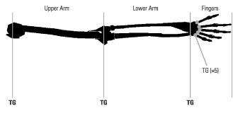
Figure 4.13 The human arm—a hierarchical model
This model is obviously hierarchical. It would be most usual if when the elbow joint was rotated the lower arm and the fingers were not also displaced. An important principle of the s