Introduction to Computer Science by Huong Nguyen - HTML preview
Download the book in PDF, ePub, Kindle for a complete version.
0 0 0 1 0 1 1 1 = 23(base 10)
× 0 0 0 0 0 0 1 1 = 3(base 10)
----------------------
1 1 1 1 1 carries
0 0 1 0 1 1 1
0 0 1 0 1 1 1
0 0 1 0 0 0 1 0 1 = 69(base 10)
Binary division follow the same rules as in decimal division.
Figure 1.8.
Logical operations on Binary Numbers
Logical Operation with one or two bits
NOT : Changes the value of a single bit. If it is a "1", the result is "0"; if it is a "0", the result is
"1".
AND: Compares 2 bits and if they are both "1", then the result is "1", otherwise, the result is "0".
OR : Compares 2 bits and if either or both bits are "1", then the result is "1", otherwise, the result is "0".
XOR : Compares 2 bits and if exactly one of them is "1" (i.e., if they are different values), then the result is "1"; otherwise (if the bits are the same), the result is "0".
Logical operators between two bits have the following truth table
Table 1.2.
x y x AND y x OR y x XOR y
1 1 1
1
0
1 0 0
1
1
0 1 0
1
1
0 0 0
0
0
Logical Operation with one or two binary numbers
A logical (bitwise) operation operates on one or two bit patterns or binary numerals at the level of their individual bits.
Example
NOT 0111
= 1000
AND operation
An AND operation takes two binary representations of equal length and performs the logical AND
operation on each pair of corresponding bits. In each pair, the result is 1 if the first bit is 1 AND
the second bit is 1. Otherwise, the result is 0.
Example
0101
AND 0011
= 0001
OR operation
An OR operation takes two bit patterns of equal length, and produces another one of the same
length by matching up corresponding bits (the first of each; the second of each; and so on) and
performing the logical OR operation on each pair of corresponding bits.
Example
0101
OR 0011
= 0111
XOR Operation
An exclusive or operation takes two bit patterns of equal length and performs the logical XOR
operation on each pair of corresponding bits.
Example
0101
XOR 0011
= 0110
Symbol Representation
Basic Principles
It is important to handle character data. Character data is not just alphabetic characters, but also numeric characters, punctuation, spaces, etc. They need to be represented in binary.
There aren't mathematical properties for character data, so assigning binary codes for characters is somewhat arbitrary.
ASCII Code Table
ASCII stands for American Standard Code for Information Interchange. The ASCII standard was
developed in 1963, permitted machines from different manufacturers to exchange data.
ASCII code table consists of 128 binary values (0 to 127), each associated with a character or
command. The non-printing characters are used to control peripherals such as printer.
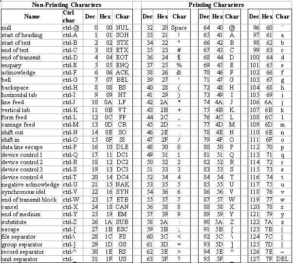
Figure 1.9.
ASCII coding table
The extended ASCII character set also consists 128 128 characters representing additional special,
mathematical, graphic and foreign characters.
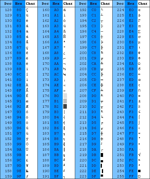
Figure 1.10.
The extended ASCII characters
Unicode Code Table
There are some problems with the ASCII code table. With ASCII character set, string datatypes
allocated one byte per character. But logographic languages such as Chinese, Japanese, and
Korean need far more than 256 characters for reasonable representation. Even Vietnamese, a
language uses almost Latin letters, need 61 characters for representation. Where can we find
numbers for our characters? is it a solution : 2 bytes per character?
Hundreds of different encoding systems were invented. But these encoding systems conflict with
one another : two encodings can use the same number for two different characters, or use different
numbers for the same character.
The Unicode standard was first published in 1991. With two bytes for each character, it can
represent 216-1 different characters.

The Unicode standard has been adopted by such industry leaders as HP, IBM, Microsoft, Oracle,
Sun, and many others. It is supported in many operating systems, all modern browsers, and many
other products.
The obvious advantages of using Unicode are :
To offer significant cost savings over the use of legacy character sets.
To enable a single software product or a single website to be targeted across multiple
platforms, languages and countries without re-engineering.
To allow data to be transported through many different systems without corruption.
Representation of Real Numbers
Basic Principles
No human system of numeration can give a unique representation to real numbers. If you give the
first few decimal places of a real number, you are giving an approximation to it.
Mathematicians may think of one approach : a real number x can be approximated by any number
in the range from x - epsilon to x + epsilon. It is fixed-point representation. Fixed-point
representations are unsatisfactory for most applications involving real numbers.
Scientists or engineers will probably use scientific notation: a number is expressed as the product
of a mantissa and some power of ten.
A system of numeration for real numbers will typically store the same three data -- a sign, a
mantissa, and an exponent -- into an allocated region of storage
The analogues of scientific notation in computer are described as floating-point representations.
In the decimal system, the decimal point indicates the start of negative powers of 10.
(1.9)
12.34=1∗ 10 1 +2∗ 10 0 +3∗ 10 −1 +4∗ 10 −2
If we are using a system in base k (ie the radix is k), the ‘radix point’ serves the same function:
(1.10)
A floating point representation allows a large range of numbers to be represented in a relatively
small number of digits by separating the digits used for precision from the digits used for range.
To avoid multiple representations of the same number floating point numbers are usually
normalized so that there is only one nonzero digit to the left of the ‘radix’ point, called the leading digit.
A normalized (non-zero) floating-point number will be represented using
(1.11)
(−1) s d 0 · d 1 d 2 ... d p−1 × be
where
s is the sign,
d 0 · d 1 d 2 ... d p−1 - termed the significand - has p significant digits, each digit satisfies 0 ≤ di <b e, e min ≤ e≤ e max , is the exponent
b is the base (or radix)
Example
If k = 10 (base 10) and p = 3, the number 0·1 is represented as 0.100
If k = 2 (base 2) and p = 24, the decimal number 0·1 cannot be represented exactly but is
approximately 1·10011001100110011001101×2 −4
Formally,
(−1) s d 0 · d 1 d 2 ... d p−1 be represents the value (−1) s ( d 0 + d 1 b −1 + d 2 b −2 ... d −1 b ( p−1) ) be In brief, a normalized representation of a real number consist of
The range of the number : the number of digits in the exponent (i.e. by e max ) and the base b to which it is raised
The precision : the number of digits p in the significand and its base b
IEEE 754/85 Standard
There are many ways to represent floating point numbers. In order to improve portability most
computers use the IEEE 754 floating point standard.
There are two primary formats:
32 bit single precision.
64 bit double precision.
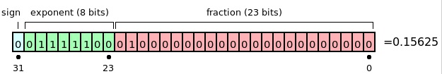
Single precision consists of:
A single sign bit, 0 for positive and 1 for negative;
An 8 bit base-2 (b = 2) excess-127 exponent, with e min = –126 (stored as
127 (10) − 126 (10) =1= 00000001 (2) ) and e max = 127 (stored as
127 (10) + 127 (10) = 254 (10) = 11111110 (2) ).
a 23 bit base-2 (k=2) significand, with a hidden bit giving a precision of 24 bits (i.e.
1. d 1 d 2 ... d 23 )
Figure 1.11.
Single precision memory format
Notes
Single precision has 24 bits precision, equivalent to about 7.2 decimal digits.
The largest representable non-infinite number is almost 2×2 127 ≅3.402823× 10 38
The smallest representable non-zero normalized number is 1×2 −127 ≅1.17549× 10 −38
Denormalized numbers (eg 0.01×2 −126 ) can be represented.
There are two zeros, ± 0.
There are two infinities, ±∞ .
A NaN (not a number) is used for results from undefined operations
Double precision floating point standard requires a 64 bit word
The first bit is the sign bit
The next eleven bits are the exponent bits
The final 52 bits are the fraction
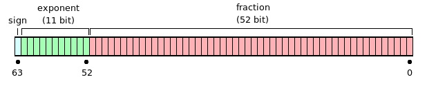
Range of double numbers : [±2.225×10−308÷±1.7977×10308]
Figure 1.12.
Double precision memory format
1.3. Computer Systems*
A computer is an electronic device that performs calculations on data, presenting the results to
humans or other computers in a variety of (hopefully useful) ways. The computer system includes
not only the hardware, but also software that are necessary to make the computer function.
Computer hardware is the physical part of a computer, including the digital circuitry, as
distinguished from the computer software that executes within the hardware.
Computer software is a general term used to describe a collection of computer programs,
procedures and documentation that perform some task on a computer system
Computer Organization
General Model of a Computer
A computer performs basically five major operations or functions irrespective of their size and
make.
1. Input: This is the process of entering data and programs in to the computer system. You should know that computer is an electronic machine like any other machine which takes as inputs raw
data and performs some processing giving out processed data. Therefore, the input unit takes data
from us to the computer in an organized manner for processing.
2. Storage: The process of saving data and instructions permanently is known as storage. Data has to be fed into the system before the actual processing starts. It is because the processing speed of Central Processing Unit (CPU) is so fast that the data has to be provided to CPU with the same
speed. Therefore the data is first stored in the storage unit for faster access and processing. This storage unit or the primary storage of the computer system is designed to do the above
functionality. It provides space for storing data and instructions.
The storage unit performs the following major functions:
- All data and instructions are stored here before and after processing.
- Intermediate results of processing are also stored here.
3. Processing: The task of performing operations like arithmetic and logical operations is called processing. The Central Processing Unit (CPU) takes data and instructions from the storage unit
and makes all sorts of calculations based on the instructions given and the type of data provided. It is then sent back to the storage unit.
4. Output: This is the process of producing results from the data for getting useful information.
Similarly the output produced by the computer after processing must also be kept somewhere
inside the computer before being given to you in human readable form. Again the output is also
stored inside the computer for further processing.
5. Control: The manner how instructions are executed and the above operations are performed.
Controlling of all operations like input, processing and output are performed by control unit. It
takes care of step by step processing of all operations in side the computer.
In order to carry out the operations mentioned above, the computer allocates the task between its
various functional units. The computer system is divided into several units for its operation.
CPU (central processing unit) : The place where decisions are made, computations are
performed, and input/output requests are delegated
Memory: stores information being processed by the CPU
Input devices : allows people to supply information to computers
Output devices : allows people to receive information from computers
Buses : a bus is a subsystem that transfers data or power between computer components inside
a computer.
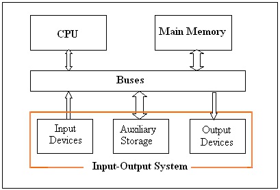
Figure 1.13.
General model of a computer
The basic function of a computer is program execution. When a program is running the executable
binary file is copied from the disk drive into memory. The process of program execution is the
retrieval of instructions and data from memory, and the execution of the various operations.The
cycles with complex instruction sets typically utilize the following stages :
Fetch the instruction from main memory
The CPU presents the value of the program counter (PC) on the address bus. The CPU then fetches
the instruction from main memory via the data bus into the Memory Data Register (MDR). The
value from the MDR is then placed into the Current Instruction Register (CIR), a circuit that holds
the instruction so that it can be decoded and executed.
Decode the instruction
The instruction decoder interprets and implements the instruction.
Fetch data from main memory
Read the effective address from main memory if the instruction has an indirect address. Fetch
required data from main memory to be processed and placed into registers.
Execute the instruction
From the instruction register, the data forming the instruction is decoded by the control unit. It
then passes the decoded information as a sequence of control signals to the relevant function units
of the CPU to perform the actions required by the instruction such as reading values from
registers, passing them to the Arithmetic logic unit (ALU) to calculate the result and writing the
result back to a register. A condition signal is sent back to the control unit by the ALU if it is
involved.
Store results
The result generated by the operation is stored in the main memory, or sent to an output device.
Based on the condition feedback from the ALU, the PC is either incremented to address the next
instruction or updated to a different address where the next instruction will be fetched. The cycle
is then repeated.
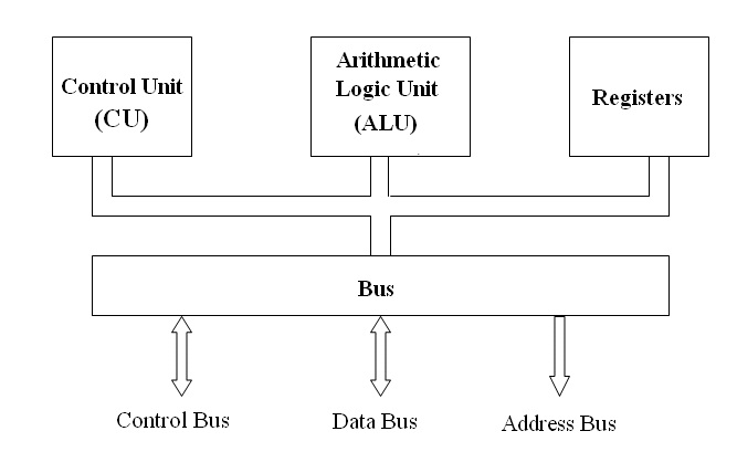
The Central Processing Unit (CPU)
You may call CPU as the brain of any computer system. It is the brain that takes all major
decisions, makes all sorts of calculations and directs different parts of the computer functions by
activating and controlling the operations.
CPU has four key parts
Control Unit
Arithmetic & Logic Unit
Registers
Clock
And, of course, wires that connect everything together.
Figure 1.14.
Basic Model of the Central Processing Unit (CPU)
Arithmetic Logic Units (ALU)
The ALU, as its name implies, is that portion of the CPU hardware which performs the arithmetic
and logical operations on the binary data .The ALU contains an Adder which is capable of
combining the contents of two registers in accordance with the logic of binary arithmetic.
Control Unit
The control unit, which extracts instructions from memory and decodes and executes them, calling
on the ALU when necessary.
Registers
Registers are temporary storage units within the CPU. Some registers, such as the program
counter and instruction register, have dedicated uses. Other registers, such as the accumulator, are for more general purpose use.
Clock
A circuit in a processor that generates a regular sequence of electronic pulses used to synchronize
operations of the processor's components. The time between pulses is the cycle time and the
number of pulses per second is the clock rate (or frequency).
The execution times of instructions on a computer are usually measured by a number of clock
cycles rather than seconds. The higher clock rate, the quicker speed of instruction processing. The
clock rate for a Pentium 4 processor is about 2.0, 2.2 GHz or higher
Memory
Memory refer to computer components, devices and recording media that retain digital data used
for computing for some interval of time. Computer memory includes internal and external
memory.
Internal memory
The internal memory is accessible by a processor without the use of the computer input-output
channels.It usually includes several types of storage, such as main storage, cache memory, and
special registers, all of which can be directly accessed by the processor.
Cache memory : A buffer, smaller and faster than main storage, used to hold a copy of
instructions and data in main storage that are likely to be needed next by the processor and that
have been obtained automatically from main storage.
Main memory (Main Storage) : addressable storage from which instructions and other data may
be loaded directly into registers for subsequent execution or processing.
Storage capacity of the main memory is the total amount of stored information that the memory
can hold. It is expressed as a quantity of bits or bytes. Each address identifies a word of storage.
So the capacity of the main memory depends on the number of bits allowed to address. For
instance, a computer allows also 32-bit memory addresses; a byte-addressable 32-bit computer
can address 2 32 = 4,294,967,296 bytes of memory, or 4 gigabytes (GB). The capacity of the main
memory is 4 GB.
The main memory consists of ROM and RAM.
Random Access Memory (RAM): The primary storage is referred to as random access memory
(RAM) because it is possible to randomly select and use any location of the memory directly
store and retrieve data. It takes same time to any address of the memory as the first address. It
is also called read/write memory. The storage of data and instructions inside the primary
storage is temporary. It disappears from RAM as soon as the power to the computer is switched
off.
Read Only Memory (ROM): There is another memory in computer, which is called Read Only
Memory (ROM). Again it is the ICs inside the PC that form the ROM. The storage of program
and data in the ROM is permanent. The ROM stores some standard processing programs
supplied by the manufacturers to operate the personal computer. The ROM can only be read by
the CPU but it cannot be changed. The basic input/output program is stored in the ROM that
examines and initializes various equipment attached to the PC when the switch is made ON.
External Memory
The external memory holds information too large for storage in main memory. Information on
external memory can only be accessed by the CPU if it is first transferred to main memory.
External memory is slow and virtually unlimited in capacity. It retains information when the
computer is switched off and is used to keep a permanent copy of programs and data.
Hard Disk: is made of magnetic material. Magnetic disks used in computer are made on the same
principle. It rotates with very high speed inside the computer drive. Data is stored on both the
surface of the disk. Magnetic disks are most popular for direct access storage device. Each disk
consists of a number of invisible concentric circles called tracks. Information is recorded on
tracks of a disk surface in the form of tiny magnetic spots. The presence of a magnetic spot
represents one bit and its absence represents zero bit. The information stored in a disk can be read many times without affecting the stored data. So the reading operation is non-destructive. But if
you want to write a new data, then the existing data is erased from the disk and new data is
recorded. The capacity of a hard disk is possibly 20 GB, 30 GB, 40 GB, 60 GB or more.
Floppy Disk: It is similar to magnetic disk discussed above. They are 5.25 inch or 3.5 inch in
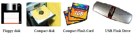
diameter. They come in single or double density and recorded on one or both surface of the
diskette. The capacity of a 5.25-inch floppy is 1.2 mega bytes whereas for 3.5 inch floppy it is
1.44 mega bytes. The floppy is a low cost device particularly suitable for personal computer
system.
Optical Disk:With every new application and software (includes sounds, images and videos) there
is greater demand for memory capacity. It is the necessity to store large volume of data that has
led to the development of optical disk storage medium. There are two commonly used categories
of optical disks: CD with the approximate capacity of 700MB and DVD with the approximate
capacity of 4.7GB
Memory Stick (Flash card, flash drive) a removable flash memory card format, with 128MB, 256
MB, 512 MB, 1 GB, 2 GB , 4 GB or more capacities
Figure 1.15.
Some types of auxiliary memory
Input-Output Devices
A computer is only useful when it is able to communicate with the external environment. When
you work with the computer you feed your data and instructions through some devices to the
computer. These devices are called Input devices. Similarly the computer after processing, gives
output through other devices called output devices.
Common input and output devices are: Speakers, Mouse, Scanner, Printer,Joystick, CD-ROM,
Keyboard, Microphone, DVD, Floppy drive, Hard drive, Magnetic tape, and Monitor. Some
devices are capable of both input and output.
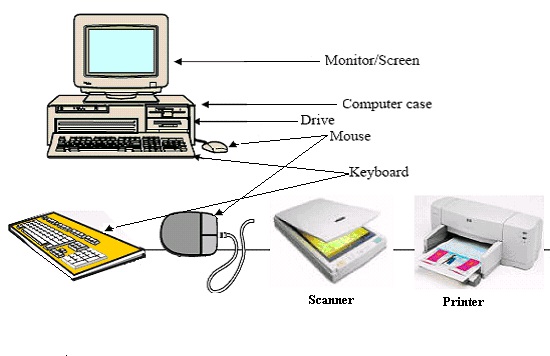
Figure 1.16.
Typical input- output devices
Input Devices
Input devices are necessary to convert our information or data in to a form which can be
understood by the computer. A good input device should provide timely, accurate and useful data
to the main memory of the computer for processing followings are the most useful input devices.
Keyboard: - This is the standard input device attached to all computers. The layout of keyboard is
just like the traditional typewriter. It also contains some extra command keys and function keys. It contains a total of 101 to 104 keys. You must press correct combination of keys to input data. The
computer can recognize the electrical signals corresponding to the correct key combination and
processing is done accordingly.
Mouse: - Mouse is an input device that is used with your personal computer. It rolls on a small
ball and has two or three buttons on the top.When you roll the mouse across a flat surface the
screen censors the mouse in the direction of mouse movement. The cursor moves very fast with
mouse giving you more freedom to work in any direction. It is easier and faster to move thr