All DOD-sponsored cargo is inspected at the overseas point of origin by customs and border clearance agents. Military equipment is inspected at the time it is placed in boxes, crates, or containers for movement and secured until departure from the overseas area. Vehicles and similar items to be shipped are inspected and secured immediately prior to loading on the departing aircraft or vessel. After the inspection is completed a DD Form 2855 ( U.S. Military Agriculture and Customs Preclearance Program) is prepared and securely affixed to the container or vehicle.
Inspectors normally check a minimum of 10 percent of all baggage 24 hours before the departure time. Once inspected, baggage is stored in a sterile area until transported and loaded at the APOE, approximately 4-6 hours prior to the scheduled departure. Soldiers process through customs with their carry-on bags and once cleared remain in the sterile area until they board the aircraft.
Detailed requirements of the military customs preclearance program can be found in Part V of the Defense Travel Regulation.
ACTIVITIES AT THE SPOE
5-10. Units normally move to the SPOE staging area from assembly areas. Some SPOEs may not have total use of the port area. Port managers and operators must closely coordinate their activities with host nation authorities as well as joint and multinational elements. Joint-use facilities and limited real estate availability may require port authorities and redeploying forces to modify processes to accommodate port capabilities.
5-11. SDDC, as the single port manager, directs water terminal operations to include supervising contracts, cargo documentation, security operations, and the overall flow of information. SDDC is responsible for providing strategic redeployment information to the CCDR and to workload the port operator based on the CCDR’s priorities and intent. Activities associated with moving Army units through SPOEs are outlined in Chapter 3.
ACTIVITIES AT THE APOE
5-12. The agencies and processes involved in moving Army units through an APOE during a deployment are similar to those at an APOE during redeployment. Customs and agricultural inspections are based on US standards.
POE STAGING AREA
5-13. Intratheater transportation assets may move units directly to a POE staging area or to an intermediate staging area. These movements are largely determined by the distance to be traveled, the size of the redeploying force, and theater capabilities. Units that were issued APS equipment usually turn it in at a separate location prior to moving to the POEs. Procedures for return of APS to storage locations are established during redeployment planning. Refer to FM 3-35.1 for additional information regarding APS.
5-14. SPOE staging operations prevent congestion within the terminal area and provide space for segregating vehicles for vessel loading. This is the final en route location for preparation of unit equipment 21 April 2010
FM 3-35
5-3
Chapter 5
for strategic movement prior to the equipment entering the port holding area. The redeployment coordination cell monitors the flow of vehicles and equipment into the port and notifies the theater movement element when there is a backlog. The TSC establishes and operates the SPOE staging area and assists with opening the staging area at the SPOE.
5-15. Movements into the POE staging area must be carefully managed to preclude congestion and to avoid exceeding the capacity of the facility. Early planning in the assembly area ensures that units arrive at the POE on time and fill scheduled modes of transportation. Instructions directing movement to the port will come in the form of a call forward message from SDDC and is based on the availability of space in the port and the TPFDD timelines.
5-16. The theater human resources (HR) manager, in coordination with the TSC is responsible for personnel accountability at the theater processing centers. The unit remains responsible for conducting strength accounting through the S-1. The HR element at the processing centers verify unit manifests, coordinate manifest changes with the USAF, and transmit final flight manifests to the appropriate commands, HR agencies, and destination installation commanders.
MOVEMENT TO POD
5-17. The combination of strategic airlift and sealift provides the capability to redeploy forces, albeit in different timeframes and along separate routes. Personnel are transported by strategic airlift to the destination APOD and then moved by bus to the destination installation. Vehicles, unit equipment, and containers are moved by strategic sealift to the designated SPOD, unloaded, and transported by convoy, commercial truck, or rail to the destination installation.
5-18. It is extremely important for the redeploying unit, assisted by their home station ITO, to maintain visibility of their vehicles and unit equipment. A small investment in maintaining visibility throughout the redeployment pipeline can be rewarded by having your vehicles equipment delivered to the right place at the right time. Otherwise there may be a delay in beginning the reset phase of ARFORGEN.
MOVEMENT TO HOME OR DEMOBILIZATION STATION
5-19. The destination for active component units is normally their home station whereas reserve component units return through a demobilization station. Typically the demobilization station is the same installation that served as the unit's mobilization station.
5-20. The supporting installation is responsible to assist returning forces until they reach their destination.
The installation coordinates the support for the arrival ports and airfields and establishes en route sites as required by the redeployment plan. Once the unit vehicles and equipment arrive at the SPOD, the destination installation has the primary role of coordinating with SDDC for onward movement. The unit is responsible to provide load/unload teams and drivers at the POD and railhead. The supporting installation has the following responsibilities at the POD—
z
Stage equipment for movement to the final destination.
z
Coordinate for customs clearance inspections.
z
Complete equipment inspections and process movement documentation.
5-21. Units returning by air to an APOD are off-loaded under the control of the CRE and moved to the holding area where they are released to the AACG. The unit remains in the holding area briefly to ensure that they have accounted for their personnel and equipment and then moves to the marshalling area where they are loaded on appropriate transportation for movement to home station, demobilization site, or other destination.
5-22. The installation will—
z
Maintain a central control and inspection point.
z
Provide a security area for sensitive items.
z
Coordinate life support facilities.
5-4
FM 3-35
21 April 2010
Redeployment
5-23. The unit will—
z
Ensure that all aircraft pallets and nets are returned to the CRE or A/DACG.
z
Perform required maintenance checks and refuel equipment.
5-24. In most instances vehicles and unit equipment are transported to their destination by commercial transportation, contracted by SDDC in coordination with the destination ITO. The ITO receives the movement documents for all equipment flowing through their areas of responsibility. They receive the commercially delivered assets, process all paperwork, and release the equipment to the unit.
5-25. The installation coordinates with SDDC and other affected agencies to provide commercial transportation and MHE as needed and monitors operations, resolves problems, and complete reports as required to higher headquarters and other coordinating organizations. Functions of the destination installation include—
z
Activating emergency operations center as required.
z
Notifying supporting units and key agencies, including Public Affairs offices and family readiness groups.
z
Activating Soldier readiness point.
z
Opening billets, dining halls, and morale, welfare, and recreation (MWR) facilities as required.
z
Conducting reception for returning units.
z
Processing personnel (health services, legal assistance, financial management, and personnel actions).
z
Providing maintenance, transportation, and MHE support.
z
Establishing turn-in of weapons and special equipment.
5-26. The unit performs the following tasks upon arrival at the destination—
z
Download and receive unit equipment.
z
Report closure of personnel and equipment.
z
Begins Reset activities.
CLOSURE REPORTING
5-27. Redeploying units must also be tracked back to their home stations and reported to the original force provider and Headquarters, Department of the Army (HQDA). This facilitates reintegration into ARFORGEN. Once redeployment begins, force tracking is conducted until the force has completed movement through the redeployment pipeline and has emerged intact at the destination. Actions taken to track and then report the closure of units back to their home stations is a command responsibility.
5-28. Reporting closure of unit personnel and equipment involves two separate but related processes. The USTRANSCOM business process, through its transportation component commands, moves personnel and equipment aboard commercial or military transportation assets. As personnel and equipment arrive at their home stations, the ITO/UMCs verify arrival by signing carrier delivery documents and reporting the arrivals back to SDDC/Air Mobility Command, noting whether or not RDDs were met. This closes the transportation business process and allows for payment to the commercial carriers.
5-29. The unit also reports their progress through their chain of command to the HQDA Army Operations Center (AOC). Interim reports begin as soon as the first elements arrive at home station and will continue until the unit commander’s report that all unit personnel and equipment are accounted for at home station and the unit is prepared for its next mission.
z
Equipment in transit is reported to the ITO and transportation discrepancy reports are submitted if it does not arrive by the RDD.
z
Forward final Unit Closure Report through chain of command to FORSCOM. (Reporting Chain of Command is dependent on C2 of given unit and installation. FORSCOM will determine and include specific reporting procedures in FORSCOM Regulation 55-1).
z
FORSCOM receives, consolidates and forwards closure reports to Army AOC/ALOC.
21 April 2010
FM 3-35
5-5
Chapter 5
z
HQDA AOC/ALOC confirms receipt of closure report, completing the closure reporting
process.
5-6
FM 3-35
21 April 2010
Appendix A
Deployment Process
The purpose of this appendix is to provide an understanding of the components and
systems that support the Army deployment process to enable mission
accomplishment. This appendix outlines use of the TC-AIMS II—Joint Force
Requirements Generator II (JFRG II)/Computerized Movement Planning and Status
System (COMPASS) deployment tools to support the deployment process.
OVERVIEW
A-1. The Army deployment process must satisfy the CJCS requirement to develop an accurate TPFDD for the first 7 days of deployment after initial deployment instructions are received. The TPFDD is a collection of movement requirements data to support deployment planning. The TPFDD includes a list of what, when, where and how equipment and personnel are to be moved. The deployment data processed through TC-AIMS into JOPES allows transportation and operational planners to perform a transportation feasibility analysis. This analysis of an OPLAN’s TPFDD determines supportability in terms of the type and amount of strategic lift assets required to accomplish planned movements within specified movement dates.
A-2. TC-AIMS II is the system of record for the Army used for the deployment of units. It includes automated support to assist unit commanders to create, maintain, manage, and update unit equipment, personnel lists, and deployment databases. TC-AIMS II integrates the Automated Air Load Planning System (AALPS) database on a single platform to enhance air load planning. Integrating AALPS provides TC-AIMS II users an enhanced capability to quickly develop balanced air load plans for deployment of cargo and passengers. AALPS allows users to configure load plans according to specific delivery methods and available aircraft. Additionally, TC-AIMS II interfaces with the Integrated Booking System (IBS) and the WPS cargo booking and manifesting application to support preparation of detailed deployment plans.
A-3. The unit movement functions are contained in four modules of TC-AIMS II:
z
Asset Management. Provides the capability to maintain personnel readiness data (licenses, equipment qualifications, medical, and immunization status, etc.), equipment, supplies, deployment support equipment, and create reports.
z
Movement Planning. Provides the capability to receive movement requirements and analyze the requirements to create tailored movement plans.
z
Movement Coordination. Provides the capability to request transportation assets and coordinate land, sea, air freight, and passenger movement requirements from origin to destination. Allows user to prioritize loads.
z
Movement Execution. Provides the capability to execute the segments and legs developed in the movement plan in a logical order. TC-AIMS II gives the user the ability to monitor unit move information and track unit cargo and assets during movements using AIT devices.
A-4. Interface capabilities allow deployment execution requirements to be reflected by exporting plan data to JFRG II/COMPASS for eventual import into JOPES. JFRG II is comprised of the following primary modules:
z
Plan Administration. Provides the capability to create and maintain adaptive and crisis action plans.
z
Unit Type Code (UTC) Summary. UTCs are alphanumeric codes used to identify a type unit and its functional description. This module provides standard planning information (table of 21 April 2010
FM 3-35
A-1
Appendix A
organization and equipment (TOE)) for personnel and cargo to include accompanying supplies associated with deployable units.
z
ULN Summary. ULNs are alphanumeric codes used to rapidly identify and associate cargo and personnel detail requirements with the movement detail to build a TPFDD.
z
Force Module Development. Provides the capability to group or aggregate ULNs and movement detail and extract them from the TPFDD. The purpose is to create manageable data sets which allow individual commands to rapidly associate TPFDD requirements with specific units and their UDL for sourcing.
z
JFRG II – TC-AIMS II Data Exchange. Provides the capability to import ‘force requirements’ into TC-AIMS II from JFRG II and to export UDL sourced ‘force requirements’
from TC-AIMS II into JFRG II.
A-5. JFRG II is a GCCS application that supports strategic force movement and sustainment. JFRG II supports TPFDD requirements associated with adaptive, crisis action, and operational planning for deployment and redeployment. JFRG II supports the Computerized Movement Planning and Status System (COMPASS) as the interim JOPES feeder system that passes TPFDD requirements from JOPES into TC-AIMS II and the validated unit deployment list back into JOPES.
A-6. JFRG II supports tactical and administrative planning by providing rapid force lift creation and lift analysis. It allows commanders visibility of allocated forces and equipment to determine the feasibility of planned movement of those forces. It also allows for analysis of lift assets required to move the force.
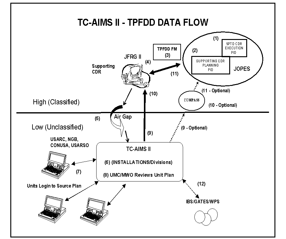
A-7. The process described below and depicted in figure A-1 presents an overview of TC-AIMS II in support of the deployment process. Its web-enabled capability allows users access to the system to perform their unit move operations from anywhere in the world, provided they have an Internet Explorer browser, a DOD-issued Internet Protocol (IP) address, and an authorized user-identification and password. The Enterprise uses web server software called CITRIX to allow users to access the TC-AIMS II database. The move to an Enterprise permits units to more easily share information and pass data between higher and lower echelons and other interface partners.
A-8. The force provider will provide specific guidance and procedures to be used in creating, validating and transmitting TPFDD data via JOPES to JFRG II to TC-AIMS II. This function consists of importing a classified JOPES plan (TPFDD) into JFRG II, creating force modules and declassifying the plan. A plan is then created on the TC-AIMS II Enterprise Server prior to importing the declassified JFRG II force module.
A-9. Force modules are created to distribute TPFDD requirements data with ULNs and movement data to TC-AIMS II. Force modules contain a grouping of unit ULNs with cargo, passenger and movement data for major subordinate elements identified for deployment. Force modules are created for all non-corps major subordinate units that have JFRG II systems, including installations with brigade or smaller sized units. Declassified TPFDDs are created for other subordinate non-divisional units without JFRG II at their level. Force modules are also created and transmitted to National Guard and USAR units tasked to deploy.
A-10. After creating a plan on the TC-AIMS II Server, the force provider imports the TPFDD and announces through the newsgroups and emails (collaboration tools) that the plan is available to the installations. Once the installation and corps have reviewed the plan they will notify the units the plan is available to match assigned personnel and equipment to plan requirements.
A-11. The step-by-step sequence for using a UDL to source a TPFDD is as follows:
• Step 1. Create TPFDD. The TPFDD is created based on coordination between the supported CCDR
and the supporting CCDR and the force provider to create an OPLAN in JOPES to outline the requirements of the supported CCDR.
• Step 2. Copy JOPES Execution Plan. The supporting CCDR accesses JOPES to create a copy of the Execution Plan with force provider requirements.
• Step 3. Create Force Modules (FM) in JOPES. Force modules contain a grouping of unit UIC/ULNs with cargo, passenger and movement data for elements identified for deployment. Force A-2
FM 3-35
21 April 2010
Deployment Process
modules are created for all units that will have a plan in TC-AIMS II for sourcing. Force modules are also created and transmitted to National Guard and USAR units tasked to deploy. JOPES operator exports FM to JFRG II.
• Step 4. JFRG II Imports the FM From JOPES. After importing the FM, the JFRG II operator conducts a series of evaluations of the data contained in the Force Module, including a function called
“Plan Evaluation” as well as reviews of GEOLOC data. When critical errors are found using ‘Plan Evaluation”, the JFRG II operator must have them corrected in JOPES before continuing, otherwise erroneous data could be forwarded to the TC-AIMS II application. This could have devastating effects on boat and aircraft scheduling and loading plans in other interfaces with TC-AIMS II. If new GEOLOC codes are found (present in JOPES but not in JFRG II) the operator manually updates the JFRG II database with the information found in the JOPES editing tool. At the conclusion of all evaluations within JFRG II, an export is made from JFRG II to the TC-AIMS II application. JFRG II automatically strips out any references to the Plan Identifier during this export. The user is thus notified with a popup message indicating it is safe to proceed with the export. This is the first step in the J6 approved Air Gap procedures (see next step).
• Step 5. Declassify TPFDD. Supporting COCOM Staff performs J6 approved Air Gap procedures to ensure no classified data is passed to unclassified systems. Air gap procedures involves following certain procedures to remove classified data prior to passing TPFDD requirements data with ULNs and movement data to an unclassified TC-AIMS II. The result is an unclassified JFRG II file transferred from the Secret network to the Unclassified net using a 3-5 inch floppy disk. The unclassified JFRG II file is then forwarded by email to the installation or unit.
• Step 6. Import Unclassified JFRG II File. The installation creates a plan on the TC-AIMS II Enterprise/Garrison server and imports the JFRG II file into the plan. The installation reviews the plan requirements and then announces through newsgroups and email (collaboration tools) that the plan is ready for UDL sourcing.
• Step 7. Source Plan. UMOs log in to TC-AIMS II to review requirements and source (match assigned equipment and personnel to plan requirements) their portion of the plan.
• Step 8. Review Sourced Plan. Units with TC-AIMS notify higher headquarters that sourcing is completed and unit equipment data in the form of a UDL has been loaded onto the server and is available for review.
• Step 9. COMPASS and JFRG II Exports. FORSCOM installations will submit both COMPASS
and JFRG II exports from TC-AIMS II to FORSCOM Headquarters. Both files are sent
simultaneously to the following email addresses: jfrgii-1@conus.army.mil and compass-1@conus.army.mil. Other Army agencies outside of FORSCOM may choose not to export anything to COMPASS, only JFRG II.
• Step 10. Import TC-AIMS II Plan. FORSCOM currently (2009) imports the COMPASS file into COMPASS and performs several data edit checks before updating the JOPES TPFDD with this UDL
data. However, when errors are discovered, the Installation is notified to correct and resubmit.
FORSCOM also reviews the data received in the JFRG II export from TC-AIMS II and compares that information with that sent to COMPASS. Other agencies may choose not to use COMPASS and will import the TC-AIMS II UDL data into JFRG II for review and verification before sending to JOPES.
• Step 11. Export Plan to JOPES. The supporting CCDR/Force Provider exports the JFRG II file to update the TPFDD in JOPES and notifies the supported CCDR. FORSCOM is waiting on several changes requested of the JFRG II Program Manager (some since 2004) before using JFRG II as the system of record to update the JOPES TPFDD as other world-wide agencies are currently doing. Until then, FORSCOM is using COMPASS to update the JOPES TPFDD.
• Step 12. Export UDL. Installation reviews plan and exports files to IBS, GATES (includes WPS) and other deployment systems.
21 April 2010
FM 3-35
A-3
Appendix A
Figure A-1. TC-AIMS II deployment process
TC-AIMS II FUNCTIONALITY
A-12. The company UMO uses TC-AIMS II to--
z
Create, maintain, manage, and update unit equipment, personnel, and deployment information files. The UMO must contact the battalion with the changes that need to be made in the deployment files or source database.
z
Develop plans for known exercises and deployment scenarios.
z
Prepare and execute convoys
z
Creates a UDL from the OEL based on information supplied either through a TPFDD or from the battalion commander. The UDL is forwarded to the battalion mobility noncommissioned officer (NCO) for further action.
A-13. The battalion plan is a UDL for the battalion (to include the headquarters company) and it is built by consolidating the company UDLs to match the requirements. Battalion movements can be constructed for the entire battalion or for slice elements depending on the mission requirement.
A-14. The battalion mobility NCO provides assistance to the company UMOs. Battalion UMO
responsibilities include (but are not limited to) using TC-AIMS II to--
z
Consolidating company movement plans and develops them into movement plans for the
battalion.
z
Auditing the company’s asset management sections for accuracy.
z
Forwarding battalion movement plans to brigade for further consolidation.
A-4
FM 3-35
21 April 2010
Deployment Process
A-15. The mobility officer or NCO in the BCT use TC-AIMS II to--
z
Consolidate battalion movement plans and develop them into movement plans for the brigade.
z
Insert movement mode data into the movement plan.
z
Forward brigade movement plans to the UMC.
z
Consolidate unit support requests for commercial transportation and forward them to the UMC.
z
Submit requests for unit convoy clearances and special hauling permits to the UMC.
A-16. At the installation level, the UMC coordinates strategic movements and assists units in developing and executing unit movement plans. UMC responsibilities include but are not limited to—
z
Providing movement guidance to all units moving from the installation.
z
Verifying the number of vessels and aircraft (determined by SDDC) required by each unit and assisting in designating loading sites and coordinating times to start and complete unit loading.
z
Assisting units in identifying and obtaining BBPCT.
z
Ensuring unit equipment is properly marked prior to movement by any mode.
z
Serving as the primary point of contact for special assignment airlift mission and exercise airlift.
z
Maintaining and managing containers and 463L pallet/cargo net allocations.
A-17. The UMC uses TC-AIMS II to--
z
Receive and process convoy clearances and special hauling permits.
z
Advise the unit on preparing movement documentation.
z
Review and export files to WPS, IBS, GATES and JFRG II.
z
Export the UDL source data to COMPASS (for a data quality check) and JFRG II.
z
Coordinate MHE requirements.
z