Compressed air distribution systems are defined as the
compressed air piping between the compressor room
7.5.3.4.3 Water Distribution Systems. Water
and the point of use. The basic components of
distribution systems are defined as all water conduits
compressed air distribution systems are piping, valves,
and supply mains, with necessary appurtenances,
expansion joints, anchors, drains, and pressure
through which water is conducted between the source
regulators. See Table 7-2 for monthly and yearly
and the point of utilization. Nonpotable water systems
inspection checkpoints.
for fire protection and sanitary purposes are included.
The basic components of systems normally found at
7.5.3.4.7 Electric Power Transmission and
waterfront facilities are: conduits, supply mains and
Distribution Systems . Electric power transmission and
service lines, valves, manholes, hydrants, meter and
distribution systems are defined as (1) overhead and
equipment for measurements and control, and all
underground transmission and distribution lines from
appurtenant equipment, such as automatic controls and
generating stations, or delivery point to all main service
cathodic protection devices. See Table 7-2 for
entrance switches in a building; (2) exterior lighting
inspection checkpoints.
systems, including street lighting, flood lighting,
perimenter lighting, and security lighting; and (3) fire
7.5.3.4.4 Sewage Collection Systems. Sewage
alarms systems.
collection systems are defined as all conduits, sewers,
and appurtenances through which domestic sewage or
industrial wastes are collected and transported between
7-14
The inspection procedure should comply with all
checkpoints.
current safety precautions, remembering that shock
hazards are intensified in the waterfront environment.
7.5.3.5 Mooring Fittings . Bollards, bitts, cleats,
See Table 7-2 for inspection checkpoints.
chocks, rings, and other steel mooring fittings must be
inspected for extent of deterioration to determine if the
7.5.3.4.8 Petroleum Fuel Distribution Systems .
fittings, holddown bolts, or foundations need repair or
Petroleum fuel distribution systems are defined as
replacement (Figure 7-6). Necessary requirements for
piping systems in which petroleum fuel is received from
painting or refilling of boltholes should be determined.
a transporting vessel or discharged from storage. The
basic components of the systems include piping, valves,
7.5.3.6 Drydocks (Graving Docks, Marine Railways,
control equipment, ground connections, signs, and
and Lifts). Drydocking facilities must be maintained to
markings. Motor vehicle fill stands, drum-filling plants,
the extent necessary to protect and preserve the
or storage tanks are not included.
structure and all operating equipment to assure full,
safe, and efficient use of the facilities at all times. See
Early detection of corrosion attack upon the
Appendix B for more information on inspection of
various fuel facility components constitutes one of the
graving docks.
most important phases of inspection (see Reference 7-
17). A record of all inspections of fuel systems should
7.5.3.7 Floating Structures. Steel pontoons, landing
be maintained. See Table 7-2 for inspection
floats, barges, floating cranes, floating caissons (graving
checkpoints.
dock entrance closures), and miscellaneous floating
structures must be inspected regularly for structural
7.5.3.4.9 Telephone Wire Systems. Telephone wire
damage, water-tightness, corrosion, condition of
systems are defined as wire communication systems
coating, and where appropriate, extent of marine
which convey intelligibility from speaker to the listener.
fouling. If marine fouling organisms are significantly
The basic components of the systems normally located
reducing the buoyancy or increasing the drag of moving
at waterfront facilities are receiver, transmission lines,
equipment, they must be removed by in-place cleaning
connecting boxes, and cable terminals.
or by cleaning after drydocking.
The inspection procedure should comply with all
current safety precautions. See Table 7-2 for inspection
SECTION 6. MAINTENANCE OF STEEL STRUCTURES
7.6.1 STRUCTURAL CONSIDERATIONS. Structural
has been chosen. Load-carrying members are usually
engineers should be consulted to ensure that the repair
replaced when 30% or more of the steel has been lost
method will restore the steel structures to the desired
by
strength and that the most effective method of repair
7-15
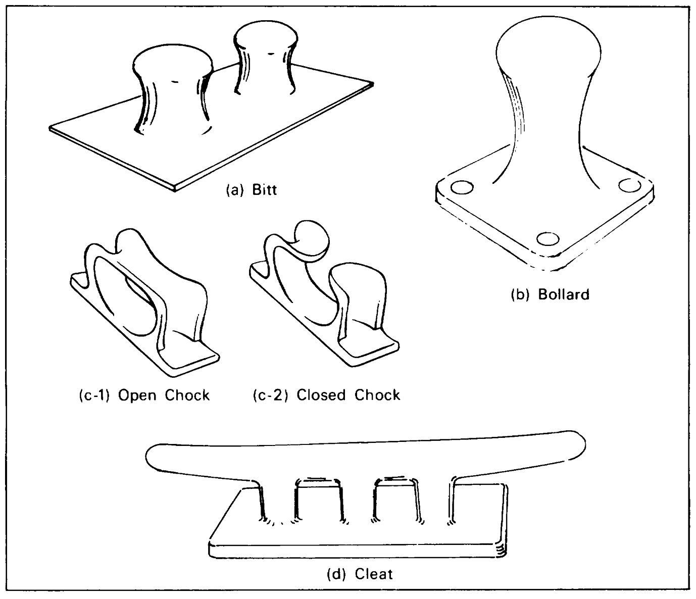
Figure 7-6. Examples of mooring fittings.
corrosion or when they are deformed. If adjacent
some cases, it may be more economical or practical to
members show signs of serious deterioration, it may be
strengthen existing members than to replace them. This
more economical to replace whole frames or bents. A
is especially true where corrosion is serious in only a
stressed member should not be removed before the
limited area.
stress has been relieved by transfer of load to adjoining
members or by new temporary members and adequate
7.6.2 PILING. Steel piling requiring coating should be
bracing. In the replacing of piles, the load should be
treated as described in 7.2. Those requiring cathodic
shifted temporarily to other piles by struts or beams
protection should be treated as described in 7.3. The
using jacks. The replacement of wales on quaywalls
may require excavation of fill to relieve lateral loads. In
7-16
cathodic protection systems themselves must be
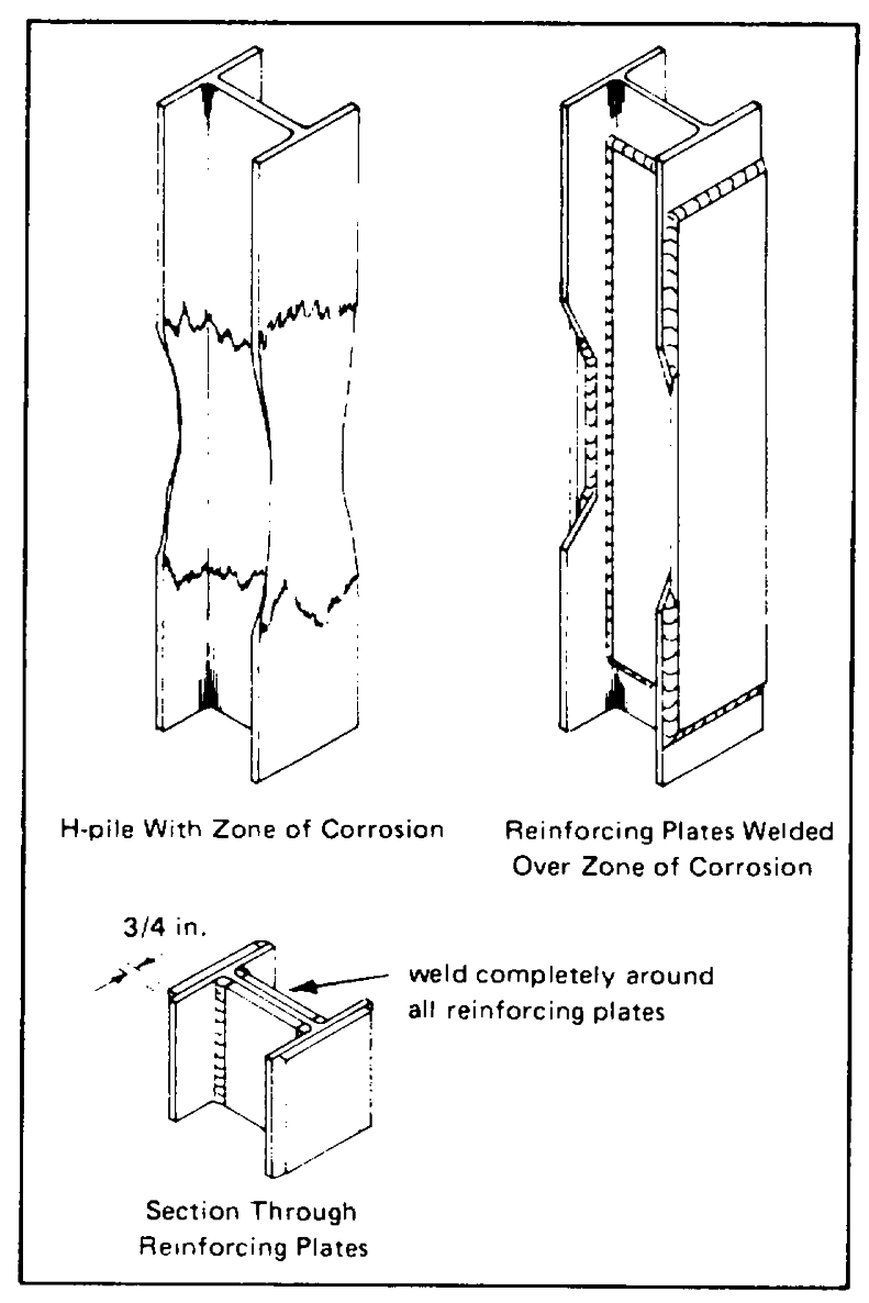
7.6.2.1 H-Piling. Reinforcement of H-piling by welding
inspected for depleted anodes, corroded or loose
steel plates onto flanges and web may be appropriate in
connections, electrical continuity, etc., and maintained
localized areas of corrosion, such as the tidal zone. The
on a yearly basis to assure continuous protection of the
reinforcing plates should be of sufficient thickness to
steel.
restore the original strength to the piling and of sufficient
area to encompass and extend beyond the extremities
of the corroded area (Figure 7-7). The old steel must be
cleaned and cut back to a point where the metal
thickness will ensure a strong weld. All cut edges
should be feathered, and the weld should be made
completely around the plate to eliminate crevices.
Another method of reinforcement utilizes
encapsulation in reinforced concrete. In this method,
reinforcing rods are welded along the main axis of the
repaired member, across the damaged area. Ties are
welded or tied at all intersections with reinforcing steel, a
form is placed around the piling, and concrete is placed
inside as described in Chapter 3. When replacement is
necessary, the new piling must be accurately fabricated
to match the old, making sure that bolt and rivet holes
are properly located. When replacing bearing piling,
the new pile is generally driven alongside the old one
at a slight angle. It is then cut off at the proper
elevation, capped (usually by welding on a steel plate),
and pulled into position with a block and tackle. If the
old pile is removed before the new one is driven, the
load must be temporarily transferred until the new pile
can assume it.
7.6.2.2 Sheet Piling. Sheet piling usually serve as a
bulkhead to retain fill. Thus, extreme care must be
taken during replacement of one or more piles to
prevent failure and passage of fill through the opened
spaces into the water. More frequently, small holes are
patched by welding steel plates over them, and badly
deteriorated piling are generally replaced or protected
by having new piles driven in front of them. In the latter
case new wales, tie rods, and deadmen should be
Figure 7-7. Repair of corroded steel pile.
7-17
installed, and the space between the old and new piles
replaced, it should be added in layers (preferably
should be filled with well-tamped earth, sand, gravel, or
granular material) and be well compacted. To replace
concrete.
deteriorated tie rods, a trench is dug from the sheet
piling to the deadman, and the new rods with new
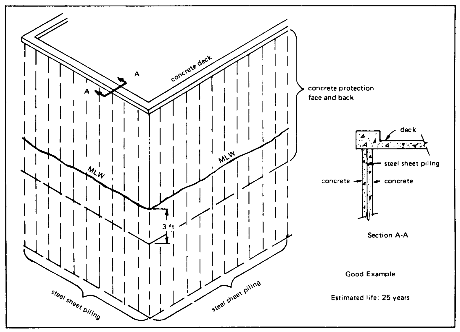
An alternate method of repairing badly
turnbuckles are installed one at a time (Figure 7-9).
deteriorated piling is to install a concrete facing. The
They should be covered with a bituminous coating, a
old steel must be cleaned of rust, marine fouling, and
fabric tape, and a final bituminous coating. The
other contaminants before a concrete cover of at least
deadman should be inspected, and necessary repairs
6-inch thickness is installed. A bolted wooden form is
made before the trench is backfilled.
generally used for this purpose. When the back of the
bulkhead is accessible, the entire steel bulkhead can be
7.6.2.3 Pipe Piling. Pipe piling repair is generally
encased in concrete with a minimum thickness of 3
similar to that of H-piling repair.
inches on each side (Figure 7-8). Whenever backfill is
Figure 7-8. Concrete-protected steel sheet piling.
7-18
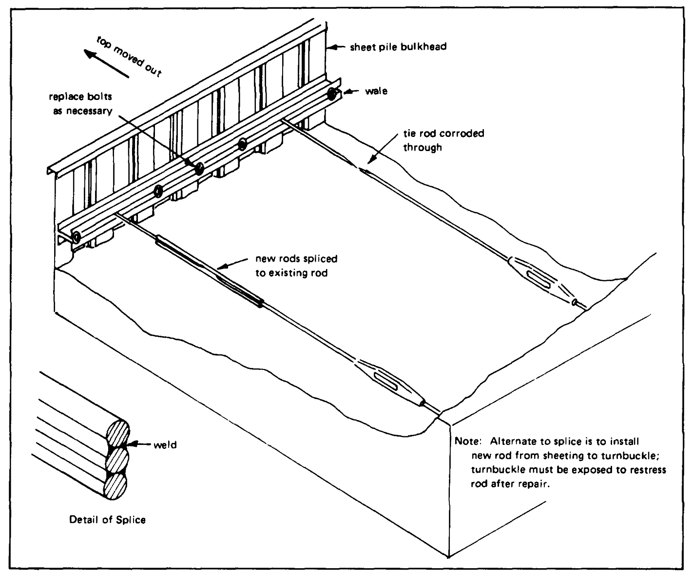
Figure 7-9. Repairing tie rods.
Because of their cylindrical shape they are more easily
maintain the distribution systems for the utilities as
protected by wraps than are other pilings.
economically as feasible and still be consistent with
operating requirements, sound engineering practice, and
7.6.3 SUPPORTING COMPONENTS. Steel supporting
proper protection to life, health, and property. All
components (wales, braces, etc.) should be repaired or
necessary repairs should be made as required by the
replaced, as necessary. As far as possible, they should
periodic inspection indicated in Table 7-2. These
be located above the high water line where corrosion is
repairs may require replacing items, tightening loose
less severe.
connections, tightening or repacking valve gland and
conduit seal
7.6.4 UTILITY LINES . The basic objective is to
7-19
glands, or welding defective parts or sections. Paints
putty. New fittings should be of cast steel and be at
and coatings should be replaced as indicated in 7.2.2
least the same size and capacity as those they replace.
and 7.2.3. References 7-18 and 7-19 give information
They should be painted with coal tar (see 7.2.3).
for protecting fuel lines under piers. The cathodic
protection systems should be maintained in accordance
7.6.6 DRYDOCKS. See Appendix. B for more
with manufacturer's instructions. In gas distribution
information on graving docks.
systems, leaking pipes are repaired by shutting off gas,
tightening connections, and rechecking leaks with
7.6.7 FLOATING STRUCTURES. Repair of holes in
soapsuds. When working on electrical power
the sides of floating structures, such as floatings, lifts,
transmission and distribution systems, an assistant must
and camels, should be made by welding on steel plates.
always be available to render assistance or first aid.
The plates should be rounded and the welding be as
Extensive replacements of defective systems shall be
smooth as possible to avoid conditions which accelerate
made in accordance with current criteria for new
corrosion. Temporary patching can be made by bolting
construction.
plates over the holes or with epoxy putty if welding of
plates would require drydocking. Cathodic protection
7.6.5 MOORING FITTINGS . Maintenance of mooring
will protect the underwater steel from corrosion, and
fittings (bitts, bollards, cleats, chocks, etc.) includes
protective coatings should be used above water.
tightening or replacing bolts; replacement of cracked,
Because of their resistance to impact and abrasion
broken or badly corroded fittings; and reinforcement or
damage and to corrosion, zinc inorganic coatings (see
replacement of foundations. Boltheads exposed to the
7.2.3) are recommended for steel work decks on barges
atmosphere should be protected from corrosion by
and cranes.
potting the bolt holes with poured lead or with an epoxy
7-20
CHAPTER 8 - PLASTIC AND ELASTOMERIC STRUCTURES
SECTION 1. TYPES OF MATERIALS
Several plastic and elastomeric materials are finding
thus, they are used to fill enclosed, hollow cavities
practical use as substitutes for wood, concrete, or steel
(Figure 8-2). Polystyrene foam (Styrofoam®) is
in waterfront structures or as components in these
relatively inexpensive to purchase in quantity and can
structures. Mention was made of them in the chapters
be cut to desired shapes. This material, covered by an
on wood, concrete, and steel, but they are described in
inverted box deck, is used extensively for small boat
this chapter in more detail.
moorings in marinas. Syntactic foams are produced by
bonding hollow glass or plastic balloons together with an
8.1.1 FIBERGLASS-REINFORCED PLASTICS. The
epoxy resin to produce a strong foam that is resistant to
reinforcement of plastics (usually polyester or epoxy)
water penetration. This type of foam is used for
with glass fibers yields a product with improved physical
buoyancy in deep-submergence operations.
properties [8-1] while retaining its light weight. The
plastics are generally quite resistant to deterioration in a
8.1.3 RUBBERS. A number of natural and synthetic
marine environment as long as no uncoated glass fibers
rubbers are molded into a variety of products, such as
are allowed to come into contact with water. Materials
fenders, that vary in size, shape, and physical
of such construction have been used in buoys (Figure 8-
properties. These products are easily secured in place
with cables or a line of bolted plates in hollow structures
or with an adhesive. They find use on piers, wharves,
8.1.2 FOAMS. Foamed plastics, which are available
landing floats, camels, mooring buoys, and pilings
with a variety of chemical compositions and physical
properties (e.g., density, strength, water permeability,
etc), are used to impart buoyancy to waterfront
8.1.4 PLASTIC WRAPS. Wraps of flexible PVC have
structures. They can be formulated to be fire-resistant,
been used to produce an oxygen deficient environment
and they can be coated for additional resistance to water
around wood piling to prevent the growth of wood boring
penetration and to deterioration by weathering.
organisms (Figure 8-4), and around steel piling to
Urethane foams are the most useful to public works
control corrosion. References 8-3 and 8-4 describe how
personnel because they can be foamed-in-place
to install this type of system on wooden piling, and
relatively easily [8-2]. Most tend to yellow and slowly
Reference 7-9 describes its use on steel piling.
degrade, however, when exposed to direct sunlight;
8-1
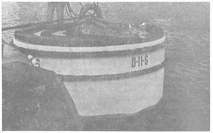
Figure 8-1. Fiberglass-reinforced plastic mooring buoy.
Figure 8-2. Pontoon filled with urethane foam to impart buoyancy.
8-2
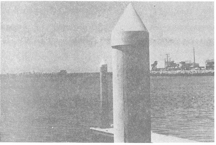
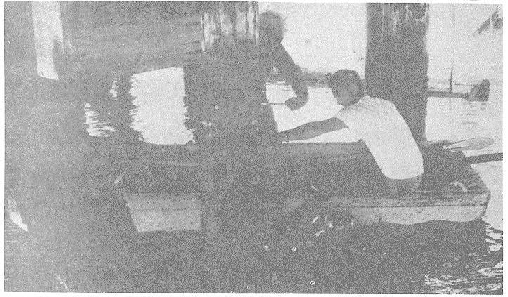
Figure 8-3. Synthetic rubber molded into pile cap. Shape keeps birds from landing and snow from collecting.
Figure 8-4. PVC barrier being installed around marine-borer-damaged pile.
8-3
8.1.5 ADHESIVES AND PUTTIES. Several chemically
susceptible to corrosion; or to patch holes above or
curing epoxy formulations have been developed that will
underwater. Reference 8-5 describes one such
bond to damp and underwater surfaces. They can be
formulation that was developed by the Civil Engineering
used to bond structures or their components; to pot
Laboratory.
connections, joints, or other metal configurations
SECTION 2. CONSTRUCTION TECHNIQUES
8.2.1 LAY-UP CONSTRUCTION . In lay-up
manner. The process is relatively expensive but
construction, alternate layers of fiberglass cloth (woven
produces a very strong and corrosion-free structure.
roving) or alternate layers of fiberglass cloth and mat
impregnated with catalyzed resin are placed over each
8.2.4 FOAMING IN-PLACE . Urethane foams can be
other on a mold or other surface to build a laminate of
poured in-place using pails of catalyzed resin or
desired strength. The first coat (gel coat) and last coat
sophisticated metering and dispensing equipment. The
of resin (usually polyester or epoxy) completely
rate of rise, density, flammability, and resistance to
encapsulate the fiberglass.
water penetration can be varied by using different
compositions.
8.2.2 SPRAY-UP CONSTRUCTION. In spray-up
construction a special spray gun is used that chops
8.2.5 PIER WRAPPING. The system described in
glass fibers and extrudes them into a spray of catalyzed
Chapter 2 for wrapping wooden piling with sheets of
resin (usually polyester or epoxy). The irregular film
PVC can be used for wrapping steel piling [7-10] .
that is formed on the mold or surface is then leveled
with a disc roller. This technique can be repeated to
8.2.6 PATCHING IN-PLACE . Holes, cuts, or dents in
build up any desired thickness of fiberglass-reinforced
metal structures can be patched with epoxy adhesives
plastic.
or putties. Formulations are available for dry and wet
surfaces, low and high temperatures, and fast and slow
8.2.3 FILAMENT WINDING . Filament winding is a
curing. The steel must be cleaned by abrasive blasting
highly specialized technique usually accomplished at a
or wire brushing before the catalyzed epoxy is placed on
factory. A structure, such as a buoy or pipe, is
it. Leaks in floating structures can be repaired only after
fabricated by winding a continuous glass filament wetted
the flow of water has been terminated.
with resin (either polyester or epoxy) around a mandrel
at the desired winding angle. Any desired thickness of
fiberglass-reinforced plastic can be produced in this
8-4
REFERENCES
1-1. Naval Facilities Engineering Command. NAVFAC
Washington, D.C., July 1968.
MO-311: Marine biology operational handbook.
Washington, D. C.., May 1965.
1-9. Naval Facilities Engineering Command. Design
manual NAVFAC DM-29: Drydocking facilities.
1-2. Naval Facilities Engineering Command. Design
Alexandria, Va, Feb 1974.
manual NAVFAC DM-25: Waterfront operational
facilities. Washington, D. C.., Oct 1971.
1-10. U.S. Department of the Army. Technical Manual
TM 5-258: Pile construction. Washington, D.C, Jun
1-3. U. S. Department of the Army. Technical Bulletin
1963.
TB ENG-250: Repair and utilities: Wood preservation.
Washington, D.C., Oct 1963.
1-11. U. S. Department of the Army. Technical Manual
TM 5-360: Port construction and rehabilitation.
1-4. U. S. Department of the Army. Regulation AR
Washington, D.C., Sept 1964.
420-10: Facilities engineering general provisions.
Washington, D. C.., Oct 1973.
1-12. Army Corps of Engineers. Guide specifications
for civil works and for military construction, May 1976.
1-5. Naval Facilities Engineering Command. NAVFAC
MO-322: Inspection guides; structural, mechanical,
1-13. Federal Construction Council. Federal
electrical, vol 2, Washington, D.C., Apr 1971.
construction guide specifications. Washington, D.C.
1-6. U. S. Department of the Air Force. Regulation
1-14. American Association of Port Authorities. Port
AFR 85-1: Resources and work force management.
design and construction. Washington, D.C., 1964. (2d
Washington, D.C., Apr 1974.
ed. published 1973 under title: Port planning, design
and construction).
1-7. U. S. Department of the Air Force. Manual AFM
86-1: Programming civil engineer resources.
1-15. American Association of Port Authorities. Port
Washington, D.C., Sept 1963.
maintenance. Washington, D.C., 1970.
1-8. Naval Facilities Engineering Command. Design
1-16. Naval Facilities Engineering Command.
manual NAVFAC DM-26: Harbor and coastal facilities.
NAVFAC MO-322: Inspection for Maintenance
Reference-1
of Public Works and Public Utilities, vol. 1, Alexandria,
2-2. Naval Facilities Engineering Command. NAVFAC
Va, Nov 1974.
MO-312: Wood preservation. Washington, D.C., Jan.
1968.