Field Manual
*FM 44-18-1
No. 44-18-1
HEADQUARTERS
DEPARTMENT OF THE ARMY
Washington, DC, 31 December 1984
S T I N G E R
TEAM OPERATIONS
* This field manual supersedes FM 44-18-1, 20 October 1980.
DISTRIBUTION RESTRICTION: Approved for public release; distribution is unlimited.
i


FM 44-18-1
31 December 1984
DISTRIBUTION RESTRICTION: Approved for public release; distribution is unlimited.
i i i
FM 44-18-1
“As part of the Army standardization program, the terms squad and team may be changed to crew. When implemented by ARs, TOEs, etcetera, the terms will be used in subsequent changes to this revised publication.”
When used in this publication, “he,” “him,” “his,” and “men”
represent both the masculine and feminine genders unless otherwise stated.
i v
FM 44-18-1
Preface
The purpose of this manual is to provide guidance for the Stinger team in support of air defense operations. It is also written to support the training of individuals to function as members of a Stinger team.
When skilled individuals are molded into efficient, smooth-functioning teams, their capability to accomplish assigned missions is greatly increased.
The effectiveness of Stinger varies directly with the individual skills of each team member and the collective proficiency of each team. The key to both is training.
This manual focuses on the techniques and procedures used by the Stinger team to engage and destroy hostile targets.
FM 44-18-1 consists of two parts:
Part I describes the Stinger system and tells how to use the weapon to shoot down aircraft. This part also describes how the team operates in combat.
Part II discusses the means and methods of training soldiers to operate the system.
This manual should be used with the system technical manual (TM
9-1425-429-12) which tells how the system functions and how to maintain it.
Information found in the technical manual, such as that on maintenance and emergency destruction procedures, is not repeated in this manual.
This is a companion manual to FM 44-18, which tells how Stinger will be employed at the platoon and section levels, along with other air defense artillery (ADA) weapons, as an integral part of the combined arms team.
The tactical doctrine and procedures contained in FM 44-18 will be of little use if the Stinger team cannot effectively engage enemy aircraft. It does little good to have the Stinger team properly positioned unless the team chief and the gunner, working together, can engage and kill an enemy aircraft when called upon to do so. This requires training in engagement procedures, as outlined in this field manual.
The material contained in this field manual is applicable to both nuclear and nonnuclear warfare without modification.
Checklists shown on pages 8 through 17 of Chapter 17, are recoin.
mended checklist formats. Those shown are samples for your guidance.
Users of FM 44-18-1 are encouraged to submit recommended changes or specific comments to improve the publication. Comments should be keyed to the specific page and line of text in which the change is recommended.
Reasons should be provided for each comment to insure understanding and complete evaluation. Comments should be prepared on DA Form 2028
(Recommended Changes to Publications and Blank Forms) and forwarded directly to:
Commandant
US Army Air Defense Artillery School
ATTN: ATSA-DTP-EB
Fort Bliss, Texas 79916-7155.
ii
PART I
T H E S T I N G E R W E A P O N S Y S T E M
CHAPTER 1
System Description
The Stinger weapon is a man-portable, shoulder-fired, infrared radiation (IR) homing (heat-seeking), guided missile system. It requires no control from the gunner after firing.
Stinger has an identification, friend or foe (IFF), subsystem which aids the gunner and team chief in identifying friendly aircraft. Operations at night or in adverse weather conditions are somewhat restricted by the gunner’s ability to see and identify the target. Stinger provides short-range air defense for maneuver units and the less mobile combat support units. The Stinger system is designed to counter high-speed, low-level, ground attack aircraft. Stinger is also a lethal weapon against helicopter, observation, and transport aircraft.
CONTENTS
Page
Page
Ready-Round . . . . . . . . . . . . . . . . . . . . . . . . 1-2
Gripstock Assembly. . . . . . . . . . . . . . . . . . . 1-6
Missile-Round . . . . . . . . . . . . . . . . . . . . . . . .1-2
IFF Support Equipment . . . . . . . . . . . . . . . . .1-7
IFF Subsystem. . . . . . . . . . . . . . . . . . . . . . . 1-5
Shipping and Storage Containers . . . . . . . . .1-9
1-1


FM 44-18-1
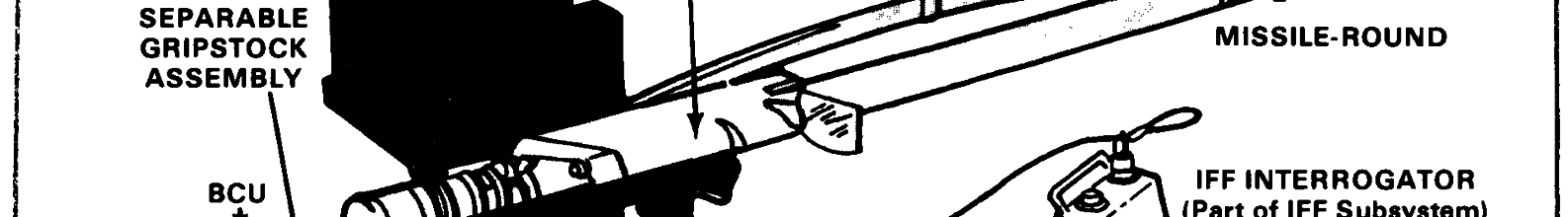
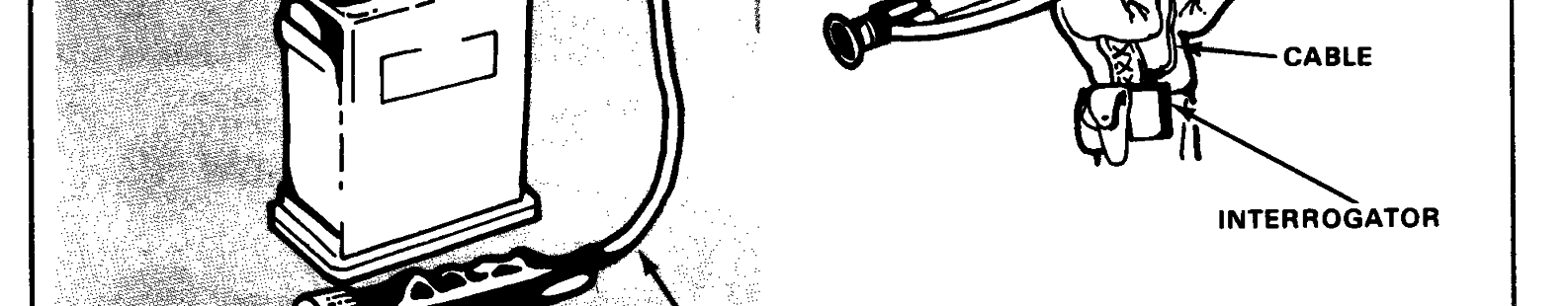
READY-ROUND
The Stinger missile-round consists of a
weapon-round to provide prelaunch power to
Stinger missile sealed in a disposable launch
the system, it becomes a ready-round. For
tube assembly. The Stinger weapon-round is
IFF capability, an IFF interrogator is con-
made up of a missile-round mated to a separ-
nected to the gripstock assembly as illus-
able gripstock assembly. When a battery/-
trated below.
coolant unit (BCU) is inserted into the
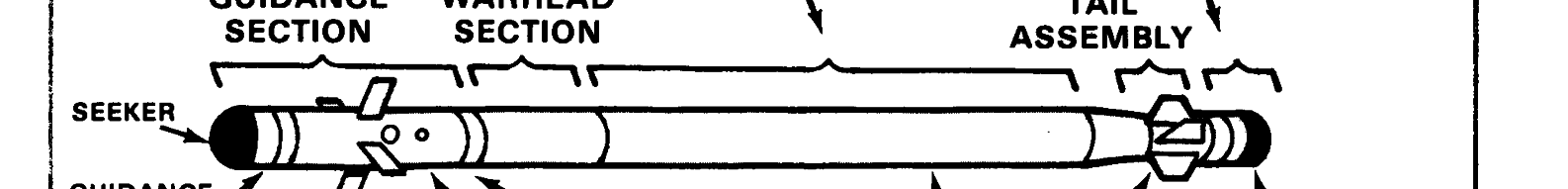
MISSILE-ROUND
Major components that make up the missile are shown in the Stinger Missile-Round illustration.
The guidance section of the missile con-
surfaces. The guidance assembly processes
sists of a guidance assembly, a control
target IR and provides guidance commands
assembly, a missile battery, and four control
for the missile during flight. The seeker tracks
1 - 2

FM 44-18-1
the IR source automatically after the gyro is
sile to its top speed. The boost phase ends, but
uncaged and during missile flight. The con-
the sustain phase continues. The sustain
trol assembly converts the guidance com-
phase maintains the missile speed for a time
mands into movement of control surfaces
sufficient to complete the mission.
which direct the flight of the missile. The
missile battery provides the in-flight power
The tail assembly of the Stinger missile
for the Stinger guided missile.
consists of four folding tailfins that provide
roll and missile stability. Within the launch
The warhead section consists of a fuze
tube, the fins are in a folded position. As the
assembly and a quantity of explosives, all
missile leaves the launch tube, the fins are
within a cylindrical case. After the flight
erected by spring action and by the force gen-
motor ignites, the fuze arms the warhead.
erated by missile spin, and then locked into
The fuze can detonate the warhead in two
place.
ways: by means of a low impact switch or by
a hard target sensor. Should target intercept
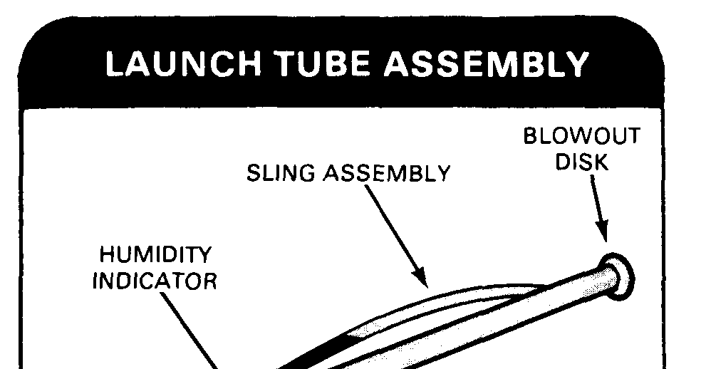
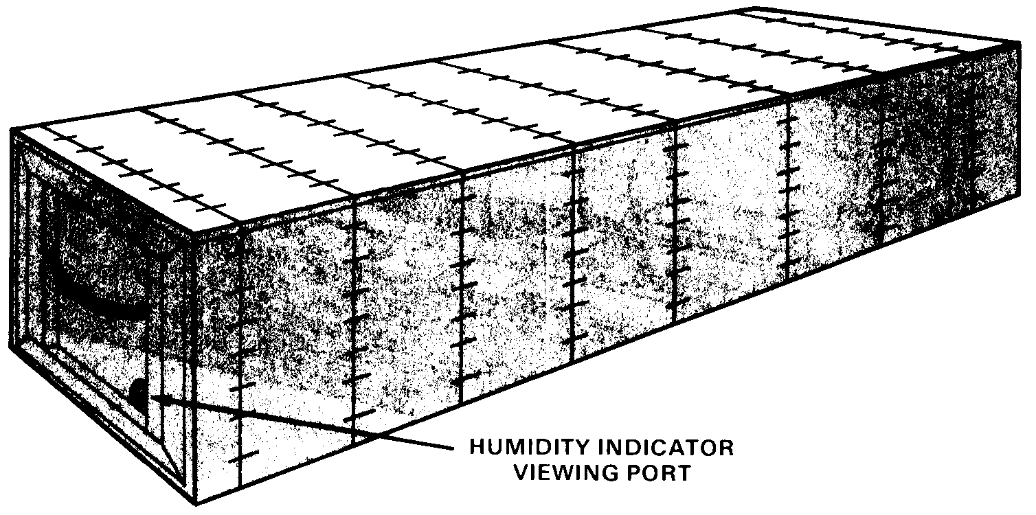
The launch tube is a fiberglass tube
not occur within 15-19 seconds after launch, a
which provides the main support for all parts
self-destruct circuit initiates warhead deto-
of the launcher. Both ends of the launch tube
nation. Safety features are included to insure
are sealed with breakable disks. The IR win-
that the missile is safe for shipping and
dow (front disk) is transparent to IR. Both
handling.
the IR window and the blowout disk (rear)
break when the missile is fired. A desiccant
The propulsion for the missile is provided
cartridge\ humidity indicator on the launch
by a separable launch motor and a dual
tube indicates whether moisture has entered
thrust flight motor.
the tube.
The launch (eject) motor provides initial
thrust that ejects the missile from the launch
tube. It allows the missile to coast a safe dis-
tance (about 9 meters/29 feet) from the gunner
prior to ignition of the flight motor. The
launch motor is expended and separated
from the flight motor before the missile is out
of the launch tube. The expended launch
motor leaves the launch tube and falls a safe
distance forward of the gunner. Also, at sepa-
ration, a lanyard attached to the launch
motor pulls the shorting plug from the flight
motor ignition circuit, thus enabling the flight
motor.
The flight motor provides propulsion for
the missile during flight. The flight motor
fires after the missile coasts for a safe dis-
tance from the gunner. Thrust for the flight
motor is provided in two phases: boost and
sustain. Initially, both burn simultaneously.
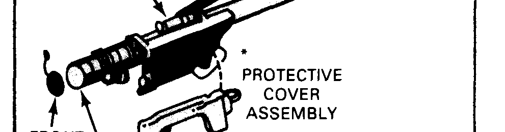
*The protective cover assemblies should be retained for possible use in the event it becomes necessary to back pack weapons without The boost phase rapidly accelerates the mis-the gripstock assemblies attached.
1-3

FM 44-18-1
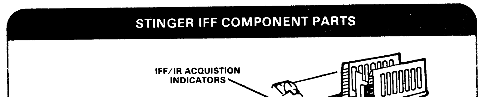
IFF SUBSYSTEM
Stinger is equipped with an IFF subsys-
tile aircraft (see Hostile Criteria, chapter 4).
tem to aid in the identification of aircraft.
The IFF components are shown in the illus-
The IFF sytem classifies aircraft as either
tration and are described in the following
friendly or unknown. It does not identify hos-
paragraphs.
The gunner initiates the IFF sequence by
with Mark X or Mark XII transponders will
pressing the IFF INTERROGATE switch on
automatically decode if the interrogator is
the gripstock assembly. Once the gunner
programmed with Modes 4 and 3. Mode 3 is
issues a challenge, the rest of the sequence is
built into the interrogator; however, if during
automatic. The IFF interrogator, attached to
programming the Mode 4 position is used,
the gunner’s belt, sends a coded challenge
Mode 3 (Mark X) will not be challenged until
(via an IFF antenna) to the aircraft. Aircraft
the 2 or 4 days of Mode 4 coded have expired.
1-5


FM 44-18-1
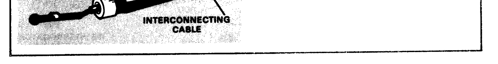
The aircraft’s transponder then prepares and
described in chapter 4.
sends a coded reply. The reply is received by
the Stinger IFF antenna and is routed to the
The IFF challenge is coded in either a
interrogator for decoding. The interrogator
complex, crypto secure Mode 4 form or a
converts the reply into an audible tone which
simpler Mode 3 form. All US combat aircraft
is then routed via the interconnecting cable
and helicopters are equipped with trans-
to the gunner as a friendly tone. If the air-
ponders to provide friendly Mode 4 and 3 re-
craft’s transponder sends an incorrect reply
plies. However, some aircraft operating in
to the IFF challenge, the reply is processed by
the combat zone, to include US commercial
the IFF system into an unknown tone. Addi-
aircraft and some aircraft belonging to our
tionally, aircraft not equipped with the trans-
allies, are not capable of providing friendly
ponders will not reply to the challenge, and
Mode 4 replies. They can only provide friendly
this is also interpreted into an unknown tone.
Mode 3 replies. Thus, since the Mode 4 code is
The gunner hears the friendly or unknown
secure, a friendly Mode 4 reply is considered a
tone in his right earphone immediately after
true friend reply. A friendly Mode 3 reply is
challenging the aircraft. The tones are further
considered only as a possible friend reply.
GRIPSTOCK ASSEMBLY
The separate gripstock assembly con-
the gripstock assembly are the safety and
tains all the necessary circuits and assem-
actuator device, UNCAGING switch, firing
blies that allow the gunner to interrogate air-
trigger, IFF antenna assembly, IFF INTER-
craft and to prepare and launch missiles. The
ROGATE switch, IFF interrogator connec-
gripstock is attached to and removed from a
tor, and BCU receptacle (see illustration
launch tube by means of a latch. Located on
below).
The antenna assembly folds into a holder
receiving coded replies. After a missile is
on the right side of the gripstock assembly
fired, the separable gripstock assembly is
when not in use. When it is deployed and the
removed from the launch tube assembly for
interrogator is connected to the gripstock, it
reuse. The separable gripstock assembly can
is capable of interrogating aircraft and
be reused until failure.
1-6


FM 44-18-1
The BCU is used to energize the wea-
ward (until a click is heard) and then released.
pon’s electrical circuits and to cool the IR
Once activated, the BCU supplies electrical
detector in the missile’s seeker prior to launch.
power and seeker coolant to the weapon for 45
It contains a thermal battery and pressurized
seconds or until missile launch. The BCU is
argon gas coolant. Prior to use, the BCU is
not reusable after it is activated. Either two
inserted into the BCU receptacle and tight-
or three BCUs are supplied with each weapon-
ened one-quarter turn. It is activated when
round and missile-round (depending on year
the safety and actuator device on the grip-
of issue).
stock is pressed forward, outward, and down-
IFF SUPPORT EQUIPMENT
Support equipment for the IFF system is
and must be safeguarded as outlined in AR
available at section headquarters. This equip-
380-40. The interrogator (specifically, the
ment includes a programmer/battery charger
reply evaluator module within the interroga-
AN/GSX-1, computer KIR-lA/TSEC (with
tor) is also classified CONFIDENTIAL and
power supply model ZAC A/1), and two code
proper security measures for it must be taken.
changing keys KIK-18/TSEC. The computer
An IFF subsystem training set is available
and code changing keys (when set with clas-
for training purposes and is described in
sified code) are classified CONFIDENTIAL,
chapter 13.
1-7


FM 44-18-1
The programmer/battery charger pro-
tinues operating in Mode 3 until the batteries
grams the IFF interrogator and charges the
are discharged or until the interrogator is
interrogator batteries. Each function may be
reprogrammed.
done separately or both may be done at the
same time. Section headquarters personnel
In the Mode 4/3 position (the normal set-
normally program and recharge the interro-
ting used for programming), the interrogator
gator and battery. A brief description of each
is programmed to interrogate in Modes 4 and
function follows. The -10 operator’s manual
3. Initial interrogation is made in Mode 4. If
and the KAM225C/TSEC may be consulted
there is no Mode 4 reply by the aircraft or the
for more detailed interrogator programming
reply is incorrect, the interrogator automati-
and battery charging procedures. Also, the
cally switches to Mode 3 and interrogates
code book (AKAK) contains coded key num-
again.
bers and instructions for destruction of the
In the Mode 4 position, the interrogator is
code book. The code book is kept at custodial
programmed to interrogate in Mode 4 only.
level. Custodians will extract and annotate
The interrogator will not automatically inter-
the code tables with the effective dates to
rogate in Mode 3 after an incorrect Mode 4
support the situation.
reply. Certain situations may require that the
interrogator be programmed for Mode 4 only
BATTERY CHARGING
operation. Tactical standing operating pro-
cedures (TSOP) dictate where the interroga-
The battery charger can charge up to six
tors will be programmed in this matter.
interrogator batteries at one time. It takes a
minimum of 4 hours to fully charge the bat-
Programming is done every 2 or 3 days,
teries. Additional charge time will not hurt
depending upon the tactical situation. The
the batteries. A freshly charged battery is
interrogator may be programmed—
installed in the interrogator prior to
By having each team turn in its interroga-
programming.
tor to section headquarters every 3 days or
less. It can be exchanged for another, if
INTERROGATOR PROGRAMMING
available, or it can be programmed and then
After a charged battery is installed, the
returned to the team.
IFF interrogator is manually programmed
for 4 days of operation. The code changing
By having the section headquarters visit
key is used to insert the proper Mode 4 codes
each team every 3 days to program the
into the computer (Mode 3 codes are already
interrogator.
built into the interrogator). The programmer
By using spare interrogators. These can be
provides the means for extracting the Mode 4
programmed at section headquarters, taken
codes from the computer and inserting them
into the interrogator.
to the teams, and exchanged there. The team’s
interrogator would then be taken to section
Either one of two programs is selected by
headquarters, programmed, and held for
operating a function switch on the program-
another team exchange. The exchange can
mer. For either program, a 4-day countdown
be done by liaison visits. For further informa-
period is started in the interrogator by the
tion on how to set the code changer key and
programmer. At the end of the 4-day period,
load the computer, refer to Limited Mainte-
an automatic time clock stops. The interroga-
nance Manuals KIR-lA/TSEC; KII-lA/
tor switches to Mode 3 operation and con-
TSEC; and KAM 225C/ SEC.
1 - 8
FM 44-18-1
SELF-CHECK
Another function of the programmer is to
with a known friendly aircraft having an
self-check the interrogator after data transfer.
operational and correctly coded Mode 4 trans-
An audio signal confirms that the interroga-
ponder. The friendly aircraft is interrogated
tor is operational and has accepted the pro-
to verify that the interrogator’s Mode 4 codes
gram selected by the programmer. An addi-