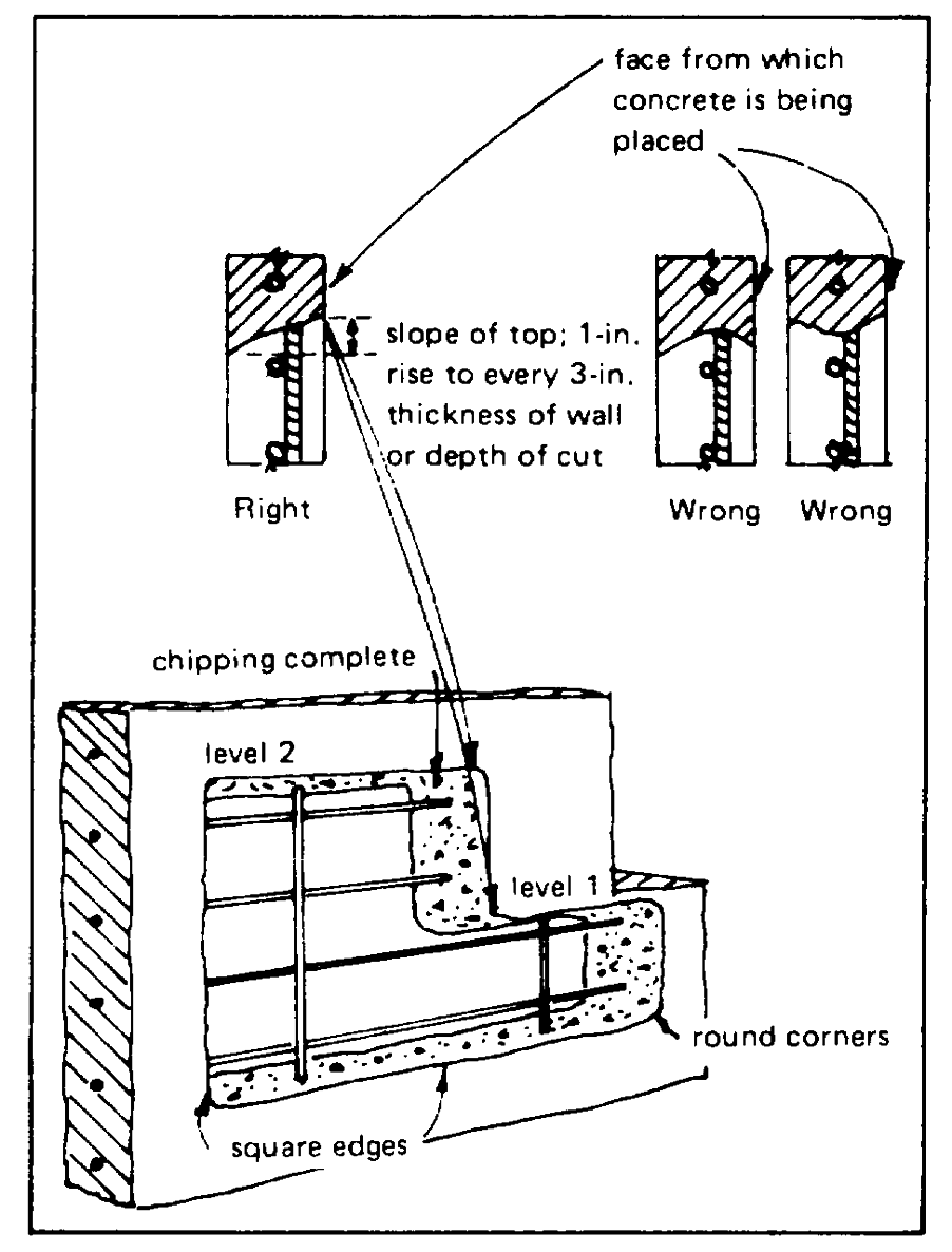
section, spalling and featheredges can be avoided by
having chippers work from both faces. All interior
corners should be rounded to a minimum radius of 1
inch.
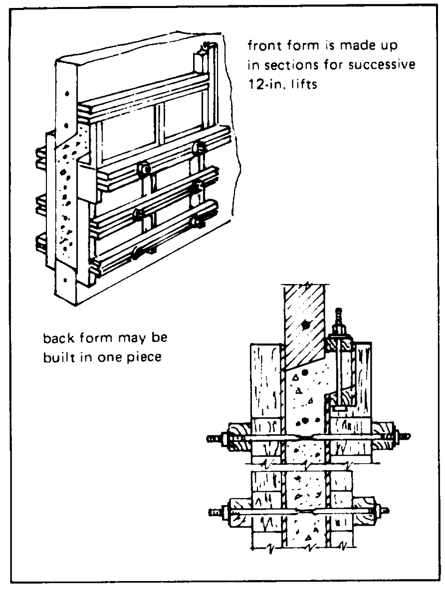
The construction and setting of forms are
important steps in the procedure for satisfactory
concrete replacement where the concrete must be
placed from the side of the structure. Form details for
walls are shown in Figure 3-6. To obtain a tight,
acceptable repair the following requirements must be
observed:
(1)
Front forms for patches more than 18
inches high should be constructed in horizontal sections
so the concrete can be conveniently placed in lifts not
more than 12 inches high. The back form can be built in
one piece. Sections to be set as concreting progresses
should be fitted before concrete placement is started.
(2)
For irregularly shaped holes, chimneys
may be required at more than one level. In some cases,
such as when beam connections are involved, a
chimney may be necessary on both sides of the wall or
beam. In all cases the chimney should extend the full
width of the hole.
(3)
Forms should be substantially constructed
so that pressure can be applied to the chimney cap at
the proper time.
(4)
Forms should be mortartight at all joints
between adjacent sections, between the forms and
Figure 3-5. Excavation of irregular area of defective
concrete, and at the tie-bolt holes to prevent the loss of
concrete where top of hole is cut at two
mortar when pressure is applied to the concrete during
levels.
the final stages of placement. Twisted or stranded
caulking cotton, folded canvas strips, or similar material
Figure 3-5). Where a hole passes through a structural
should be used as the forms are assembled.
element, it may be necessary to fill the hole from both
sides. In this case the slope of the top of the cut should
Immediately before placing the front section of
be modified accordingly.
form for each lift, the surface of the old concrete (at the
sides which will be covered by new concrete) should be
(4)
The bottom and sides of the hole should be cut
coated with a 1/8-inch-thick layer of mortar. This mortar
sharp and approximately square with the face of the
should have the same sand and cement content and the
wall. When the hole goes entirely through the concrete
3-11
sectional area of the hole is greater than 36 and less
than 72 square inches for reinforced concrete repair or
144 square inches for nonreinforced concrete repair, a
no-slump concrete should be placed, thoroughly
vibrated, and power tamped in 3-inch layers. If
practicable, the new concrete should be preshrunk by
letting it stand as long as practicable before it is tamped
into the hole. The mix proportions and the aggregate
gradation should be selected for minimum water
content. The W/C weight ratio should be less than 0.40.
Casting concrete in open-top forms, as used for
the reconstruction of the top of bulkheads and pier-deck
curbs, is a comparatively simple operation. The W/C
weight ratio should not exceed 0.45. No special
features are required in the forms, but they should be
mortartight when vibrated, and should give the new
concrete a finish similar to that of the adjacent areas.
The slump should be as low as practicable, and the
amount of air-entraining agent increased as necessary
to ensure the maximum permissible percentage of
entrained air, despite the low slump. Top surfaces
should be sloped so as to provide rapid drainage.
Manipulation in finishing should be held to a minimum,
and a wood-float finish is preferable to a steel-trowel
finish. Edges and corners should be tooled or
chamfered. Water should not be used to aid in
finishing.
Forms for repairs involving cast-in-place
Figure 3-6. Details of forms for concrete replacement in
concrete can usually be removed the day after casting
bulkheads.
unless form removal would damage the newly placed
concrete. The projections left by the chimneys should
same W/C ratio as the mortar in the replacement
normally be removed the second day. If the trimming is
concrete. The surface should be damp, but not wet.
done earlier, the concrete tends to break back into the
The mortar can be applied by means of an air-suction
repair. These projections should always be removed by
gun, by brushing, or by being rubbed into the surface
working up from the bottom because working down from
with the hand encased in a rubber glove. Concrete
the top tends to break concrete out of the repair.
placement should follow immediately. If the cross-
3-12
3.4.4 SHOTCRETE. Shotcrete is satisfactory for
repairing a deteriorated waterfront structure is: (1)
repairing minor damage to concrete piles and framed
remove all defective concrete, (2) clean all rust off
structures and should be considered whenever there is
exposed reinforcement, (3) roughen all smooth surfaces
enough repair work to justify the cost of the equipment.
and either wire brush or abrasive blast the exposed
Piers, navigation locks, wooden piling, concrete piling,
underlying concrete surfaces, (4) instill wire fabric and
and steel piling are typical applications for shotcrete
ensure that the laps do not project more than 3/4 inch
where waterfront repairs are necessary.
from the surface of the underlying concrete, (5) fix the
profiles, (6) fill out with shotcrete to the original face of
The advantages of shotcrete, compared with
the structure, and (7) apply not less than 2 inches of
either regular concrete or prepacked concrete, are: (1)
shotcrete (the final coat should not be less than 1/2 inch
ease of placement, (2) minimum need for formwork
thick).
and plant equipment, and (3) high strength. The
comparative disadvantages of shotcrete are: (1)
3.4.5 PREPACKED CONCRETE. Prepacked concrete
susceptibility to wide structural variation (composition is
is used on large repair jobs, particularly underwater
dependent on the skill of the nozzle man), (2) drying
placement or where placement of regular concrete
shrinkage rate and coefficient of thermal expansion can
would be either difficult or impossible. This method is
be considerably different than those of the original
used also in restoring old concrete and masonry
concrete in the structure being repaired, and (3)
structures. The advantages of either regular concrete or
relatively high porosity.
prepacked concrete, compared with shotcrete, are:
greater density, greater uniformity, lesser permeability,
Repairs and restorations accomplished by the
lower shrinkage, less dependence on personal skills of
shotcrete method are economical and successful where
equipment operators, less dust, less clean-up work, and
deterioration is shallow and the repaired area is large
more economical. The comparative disadvantages of
and irregular. In regions of severe exposure, periodic
these two methods are that all work on vertical surfaces
protective applications are necessary to seal cracks that
requires formwork, and for extensive restoration the
allow the entry of water. More information can be found
plant required could be considerably more expensive
in References 3-2, 3-3, and 3-4.
than that required for shotcrete placement.
With shotcrete, only that amount of water
Prepacked concrete entails placing coarse
necessary for hydration is added to the mixture of
aggregate in the form and filling the voids in the
aggregate and cement. Thus, shotcrete can be more
aggregate mass with intrusion grout that consists of
dense than regular concrete, an important factor in the
portland cement, a high grade pozzolan, sand, water
resistance of concrete to weathering. The ratio of
and an intrusion aid. The intrusion aid is a chemical
cement to aggregate should never be greater than 1 to
admixture that suspends the solid particles in the grout,
3.5; these proportions will result in a ratio of about 1 to
provides fluidity at low W/C ratios, and undergoes slight
2.5 (by weight) after gunning the shotcrete in place.
expansion before final set. The volume of air entrained
in the intrusion grout is about 9%. The amount in the
The recommended shotcrete procedure for
3-13
hardened concrete depends on the ratio of grout to
It is general practice to use a steel tremie, but a
coarse aggregate, but usually is about 4%. Bonding
rigid rubber hose could be substituted. An aluminum
strengths of prepacked to regular concrete are between
alloy tremie should never be used because an adverse
70% and 100% of that attainable in regular concrete.
chemical reaction may occur to produce inferior
This makes it possible to restore deteriorated concrete
concrete [3.5]
members to near their original strengths or to enlarge
existing members to take additional loads.
The size of the tremie depends on the
maximum size of gravel and on the quantity of concrete
Weakened material should be removed to
to be emplaced; the usual range in diameter is from 8 to
expose sound concrete, and the surfaces of sound
18 inches. Records of underwater construction show
concrete should be roughened by either chipping or
rates of lineal flow between 3/4 and 1 foot per second.
heavy sandblasting before repairing. Space must be
The slump of tremie concrete must be maintained
provided for the replacement or addition of at least 3 to
between 6 and 7 inches.
4 inches of new prepacked concrete. Forms are then
well-anchored to the old concrete, filled with coarse
3.4.7 PUMPED CONCRETE. Pumping freshly mixed
aggregate (of proper gradation for the thickness being
concrete is the most expeditious means of placing
placed), and the grout intruded. When the forms are
concrete in spaces of limited accessibility. The pumping
filled, a closing pressure of about 10 psi is held for
method offers several advantages: (1) High quality
several minutes to drive out all air and water through a
concrete is required because the mixture must be
vent at the highest point. The forms are removed one
workable in order to pass through the pump; (2)
or two days later, and the new concrete is properly
Workable mixtures containing relatively small coarse
cured.
aggregate particles tend to provide a dense concrete;
(3) The pump pressure helps to coat the aggregate
3.4.6 TREMIE CONCRETE. One method of placing
particles more uniformly and, thus, increase the density
concrete underwater, especially at easily accessible
of the resultant concrete; (4) Concrete can be
locations, involves a tremie (a steel tube having a
transferred from a barge directly into wooden forms at
hopper for filling at its upper end). A plug, consisting of
the patching site; and (5) Pumped concrete can be used
either a rubber ball or a wad of burlap that fits snugly
to fill the forms from the bottom upwards, displacing the
inside the tremie, is inserted below a loading hopper
seawater as additional concrete is forced in at the
located at the upper end of the tremie. The freshly
bottom.
mixed concrete, introduced at the hopper, forces the
plug down and displaces the seawater. The tremie is
The pumping method also has some
continually replenished with concrete while the lower
disadvantages: (1) The slump must be carefully
end is kept embedded in the newly deposited concrete.
controlled to prevent segregation as excessively wet
Tremie concrete must be quite workable so that it flows
mixtures will sometimes segregate; (2) Coarse
readily into place.
aggregate should consist of rounded particles as
crushed stone mixtures are comparatively difficult to
3-14
airentrained concrete will cause little reduction in air
content.
The pipeline should be either horizontal or
vertical rather than inclined, wherever possible. With an
inclined pipeline any water bleeding from the freshly
mixed concrete within the pipeline will collect above the
concrete and run down the inside of the pipeline.
Delays as long as 1-1/2 hours can generally be
tolerated if the mixture is moved several feet at least
every 10 minutes (while in the hose or pipeline) until
continuous pumping is resumed.
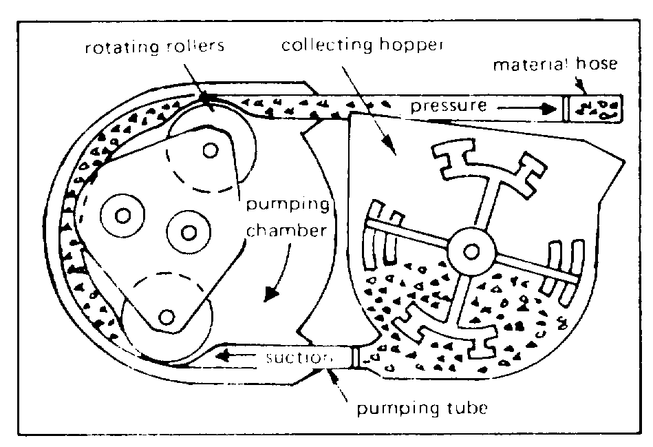
The concrete should be pumped as near to its
final underwater position as possible. The diver who
Figure 3-7. Typical squeeze-type concrete pump.
has control of the discharge end should not permit
lateral flow within the open-top form of more than 2 or 3
pump because the angular particles tend to interlock;
feet. The discharge end of the line has to be buried in
and (3) Porous aggregates (e.g., expanded clay, foamed
the mass of fresh concrete; otherwise, segregation will
slag, pumice, and many corallin, materials) should be
occur at the point where the concrete comes out.
avoided, if denser aggregates are available.
Aluminum pipe should not be used because an adverse
chemical reaction with the concrete will occur. Rubber
The squeeze-type pump (Figure 3-7) is
hose should only be used for discharge lines or for very
preferred for pumping freshly mixed concrete into the
short pumping distances. The pipeline should be
form because few of the pump parts contact the
protected from any excessive heat (solar included).
concrete. This pump is easy to clean and does not
place the concrete under great pressure.
3.4.8 EPOXY RESIN. Cracks and joints in concrete
waterfront structures must be sealed against the
When air-entraining agents are required as
adverse effects of a marine environment as a means of
described in 3.1.2.4, they are dissolved in the mixing
prolonging the lives of such facilities. Various
water before it enters the concrete mixer. Quantities
formulations of epoxy resin compounds are used for
needed per bag of cement are specified by the
sealing, grouting, patching, and waterproofing cracks
manufacturer and are shown on the containers.
and joints in concrete, and as adhesives for bonding
Normally about 2 fluid ounces per bag of cement are
freshly mixed concrete or precast concrete to old
used.
concrete. No formulation can serve as an all-purpose
material for these applications, and so each epoxy
Water-reducing admixtures will also improve the
formulation should be used only for its intended
pumpability of the concrete. If admixtures are used, do
purpose. Proper methods of treating the surfaces of
not decrease the cement composition; to do so would
concrete and
probably cause blockage in the pipeline. Pumping
3-15
reinforcing steel preparatory to applying the epoxy
compound, and correct procedures for using epoxy
compounds are described in detail in References 3-6 through
3.4.9 PROTECTIVE COATINGS. Coating hardened
concrete surfaces (e.g., the decks of piers and wharves) with
protective water repellents may be a good precautionary
measure. A useful guide to coatings for protecting concrete
3-16
CHAPTER 4 - STONE MASONRY STRUCTURES
SECTION 1. INTRODUCTION
4.1.1 BACKGROUND. Throughout the 19th century,
(Figure 4-1). These structures usually incorporate
stone masonry was generally used in constructing
massive gravity walls, the stability of which is a function
graving docks, quay walls, and wharves. As late as the
of their mass. The designers of masonry waterfront
1850s, the cut stones of granite were set in lime mortar;
structures specified greater mass, proportional to the
after that, they were set in portland cement mortar.
expected loads, than is customary with mass concrete
used today. Granite masonry usually develops no
4.1.2 DESIGN. In most instances the quarried and
maintenance problems except at the joints.
trimmed building stone used in graving docks is granite
SECTION 2. METHOD OF INSPECTION
4.2.1 VISUAL. The stone blocks in these old waterfront
width of cracks in adjacent paved areas atop the earth
structures have been subjected to weathering,
behind the walls. If leaks are detected, note the rate of
extraordinary loads, abrasion, and seawater. The best
discharge and whether or not material is suspended in
visual indication of how well they have resisted
the water. Divers should investigate for scour and
weathering is their general appearance. Blocks of high-
undermining, especially outside the closure (Figure 4-2).
quality stone retain their sharp edges and corners and
their delicate tool marks for many years. After a century
4.2.2 SETTLEMENT. If settlement of the structure is
of service, these distinguishing attributes may no longer
suspected, establish points for a level survey; locate
be present.
these points on both sides of each suspected joint and
at both ends of the masonry structure; these points
Empty graving docks should be inspected for
should be related to permanent bench marks
leaking groundwater through the joints in their stone
established previously by the U.S. Coast and Geodetic
floors and sidewalls and for leaking seawater around the
Survey. For a graving dock, these points should be
seals of the closure to the basin. All joints should be
located at the tops of the sidewalls, at the floor adjoining
examined for cracks and erosion. The earth behind the
the sidewalls, along the longitudinal centerline of the
sidewalls should be inspected periodically for
floor, and along the outer rail of the crane track. Note
settlement. Movement of the sidewalls of a graving
any condition that could reveal settlement.
dock or quaywalls is usually revealed by an increase in
4-1
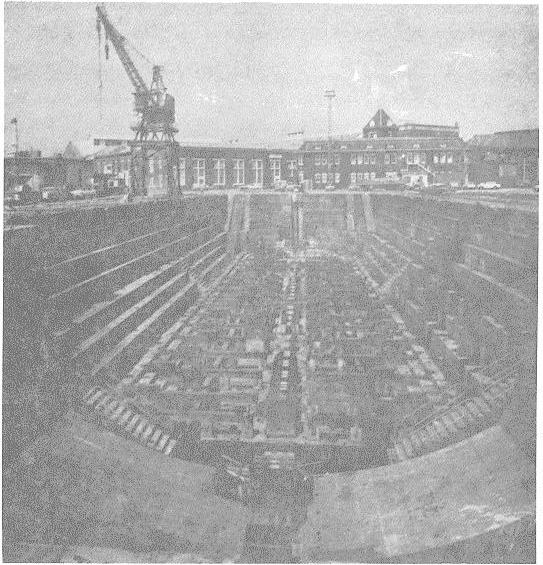
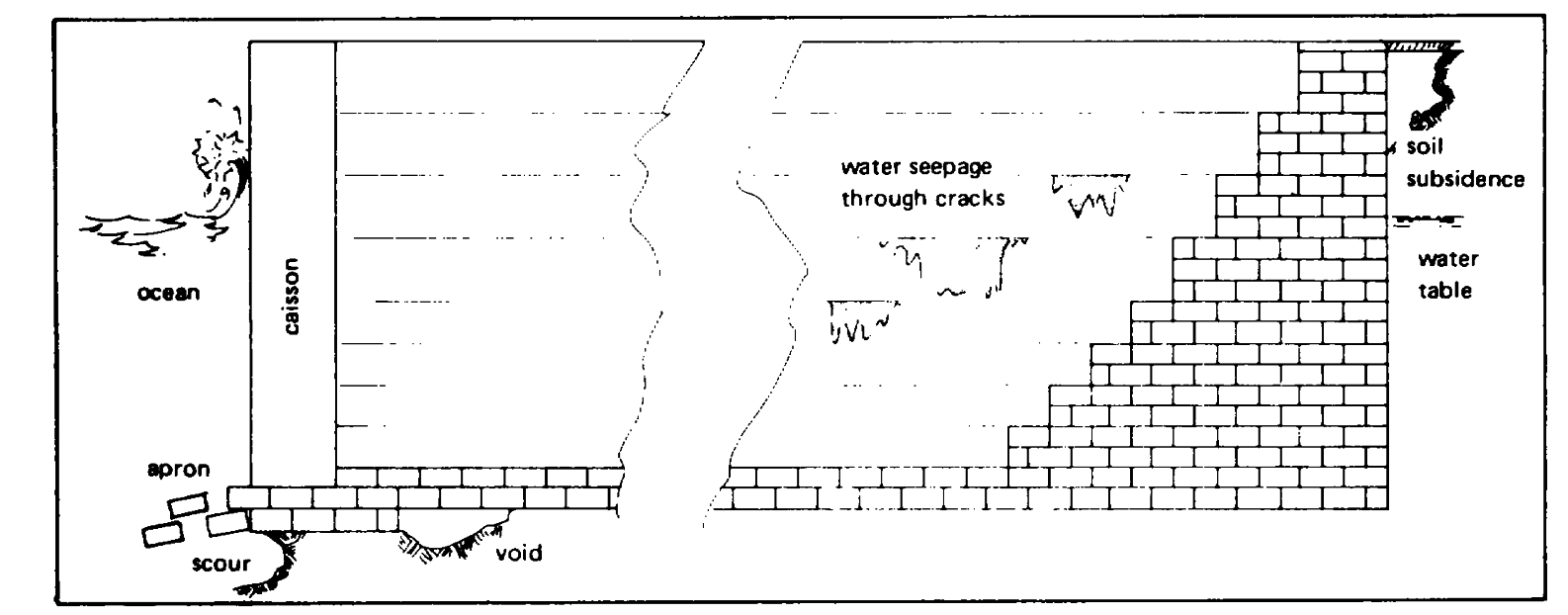
Figure 4-1. Masonry graving dock.
Figure 4-2. Types of deterioration that will require repair.
4-2
4.2.3 DOCUMENTATION . Periodically record and/or
should include the data and a scalar guide to enable the
photograph cracks and related defects to ensure
viewer to better understand the magnitude of the defect.
documentation of progressive failure; each photograph
SECTION 3. METHODS OF REPAIR
4.3.1 ENGINEERING INVESTIGATION . If a masonry
in vertical joints. If the masonry exhibits signs of
quaywall or graving dock has moved as the result of
leakage, hairline cracking can also be present in the
sliding at the foundation, a structural analysis to
horizontal beds of mortar. Spalled mortar can be
determine the cause is necessary before any restoration
caused by many cycles of alternate freezing and
is attempted. An investigation of the settlement may
thawing.
involve pumping dyed water through cracked or leaky
joints to determine the extent of hidden cavities or
4.3.4 TUCK-POINTING. Defective joints can usually be
voids; the existence of a cavity would be confirmed by
repaired by tuck-pointing with portland cement mortar; a
finding the colored water at some drainage outlet. After
skilled stone mason is required. Tuck-pointing only the
such an investigation has yielded the location, depth,
obviously defective joints does not ensure that the
and extent of the cavity or void, a program of grouting
untreated joints will not leak; therefore all joints, vertical
must be planned.
and horizontal, in the face of the wall should be tuck-
pointed. This procedure requires removing and
If any portion of the masonry structure is
replacing all mortar to a depth of at least 5/8 inch
damaged, or if any stone blocks are loose, repairs
throughout every joint. Each joint is raked to a depth
should ensure that the bond between the blocks is
not greater than 1 inch, unless the old mortar is so
restored. If a masonry quaywall or sidewall of a graving
defective that removal to a greater depth is necessary.
dock is cracked due to unequal settlement, restoration
The depth of old mortar removed should be such that
should be delayed until the cause of settlement has
sound mortar will serve as the base for the new mortar.
been corrected.
All exposed sound mortar must have a clean, square-cut
surface. All dust and dirt within the raked joint should be
4.3.2 WEEP HOLES. If there is evidence that water is
washed out by a jet of water. Wherever old mortar is
collecting behind the quaywall, and if weep holes are
raked out deeper than 1 inch, the hollow spots must be
part of the installation, the holes should be cleared to
filled with new mortar first so that a uniform line is
allow drainage. If this procedure is insufficient to relieve
created. The cleaned joints are tuck-pointed with the
the pressure, additional weep holes should be drilled.
portland cement mortar while the masonry is still damp
(not wet) from washing out the raked joints.
4.3.3 SHRINKAGE CRACKS. Shrinkage cracks in joint
mortar appear as hairline cracks; they are usually found
4-3
The mortar is mixed at least 1 hour before use to ensure
provided the cement-base stabilizing mixture contains
prehydration, which stabilizes the plasticity and
an intrusion aid. The consistency of the intrusion
workability of the mortar and minimizes any tendency to
mixture is that of a smooth slurry. This mixture is
shrink after insertion into the joint opening. A suitable