The hard disk drive has short and fascinating history. In 24 years it evolved from a monstrosity with fifty two-foot diameter disks holding five MBytes (5,000,000 bytes) of data to today's drives measuring 3 /12 inches wide and an inch high (and smaller) holding 400 GBytes (400,000,000,000 bytes/characters). Here, then, is the short history of this marvelous device.
Before the disk drive there were drums... In 1950 Engineering Research Associates of Minneapolis built the first commercial magnetic drum storage unit for the U.S. Navy, the ERA 110. It could store one million bits of data and retrieve a word in 5 thousandths of a second..
In 1956 IBM invented the first computer disk storage system, the 305 RAMAC (Random Access Method of Accounting and Control). This system could store five MBytes. It had fifty, 24-inch diameter disks!
By 1961 IBM had invented the first disk drive with air bearing heads and in 1963 they introduced the removable disk pack drive.In 1970 the eight inch floppy disk drive was introduced by IBM. My first floppy drives were made by Shugart who was one of the "dirty dozen" who left IBM to start their own companies. In 1981 two Shugart 8 inch floppy drives with enclosure and power supply cost me about $350.00. They were for my second computer. My first computer had no drives at all.
In 1973 IBM shipped the model 3340 Winchester sealed hard disk drive, the predecessor of all current hard disk drives. The 3340 had two spindles each with a capacity of 30 MBytes, and the term "30/30 Winchester" was thus coined.
In 1980, Seagate Technology introduced the first hard disk drive for microcomputers, the ST506. It was a full height (twice as high as most current 5 1/4" drives) 5 1/4" drive, with a stepper motor, and held 5 Mbytes. My first hard disk drive was an ST506. I cannot remember exactly how much it cost, but it plus its enclosure, etc. was well over a thousand dollars. It took me three years to fill the drive. Also, in 1980 Phillips introduced the first optical laser drive. In the early 80's, the first 5 1/4" hard disks with voice coil actuators (more on this later) started shipping in volume, but stepper motor drives continued in production into the early 1990's. In 1981, Sony shipped the first 3 1/2" floppy drives.
In 1983 Rodime made the first 3.5 inch rigid disk drive. The first CD-ROM drives were shipped in 1984, and "Grolier's Electronic Encyclopedia," followed in 1985. The 3 1/2" IDE drive started its existence as a drive on a plug-in expansion board, or "hard card." The hard card included the drive on the controller which, in turn, evolved into Integrated Device Electronics (IDE) hard disk drive, where the controller became incorporated into the printed circuit on the bottom of the hard disk drive. Quantum made the first hard card in 1985.
In 1986 the first 3 /12" hard disks with voice coil actuators were introduced by Conner in volume, but half (1.6") and full height 5 1/4" drives persisted for several years. In 1988 Conner introduced the first one inch high 3 1/2" hard disk drives. In the same year PrairieTek shipped the first 2 1/2" hard disks.
In 1997 Seagate introduced the first 7,200 RPM, Ultra ATA hard disk drive for desktop computers and in February of this year they introduced the first 15,000 RPM hard disk drive, the Cheetah X15. Milestones for IDE DMA, ATA/33, and ATA/66 drives follow:1994 DMA, Mode 2 at 16.6 MB/s
1997 Ultra ATA/33 at 33.3 MB/s
1999 Ultra ATA/66 at 66.6 MB/s
6/20/00 IBM triples the capacity of the world's smallest hard disk drive. This drive holds one gigabyte on a disk which is the size of an American quarter. The world's first gigabyte-capacity disk drive, the IBM 3380, introduced in 1980, was the size of a refrigerator, weighed 550 pounds (about 250 kg), and had a price tag of $40,000.
2.Main technical specification and parameter of hard diskCapacity
We can see the capacity in two aspects: the total capacity and the capacity of one disk. The whole capacity is made up of each disk capacity.
If we increase the disk capacity, we would not only improve the disk capacity, improve the speed of transmission, but also cut the cost down.
Rotate speed.
Rotate speed is the speed disk rotate. It is measured by RPM (Round Per Minute).The rotate speed of IDE hard disk are 5400RPM, 7200RPM etc.
Average Seek Time
The average seek time gives a good measure of the speed of the drive in a multi-user environment where successive read/write request are largely uncorrelated.
Ten ms is common for a hard disk and 200 ms for an eight-speed CD-ROM.
Average Latency
The hard disk platters are spinning around at high speed, and the spin speed is not synchronized to the process that moves the read/write heads to the correct cylinder on a random access on the hard disk. Therefore, at the time that the heads arrive at the correct cylinder, the actual sector that is needed may be anywhere. After the actuator assembly has completed its seek to the correct track, the drive must wait for the correct sector to come around to where the read/write heads are located. This time is called latency. Latency is directly related to the spindle speed of the drive and such is influenced solely by the drive's spindle characteristics. This operation page discussing spindle speeds also contains information relevant to latency.
Conceptually, latency is rather simple to understand; it is also easy to calculate. The faster the disk is spinning, the quicker the correct sector will rotate under the heads, and the lower latency will be. Sometimes the sector will be at just the right spot when the seek is completed, and the latency for that access will be close to zero. Sometimes the needed sector will have just passed the head and in this "worst case", a full rotation will be needed before the sector can be read. On average, latency will be half the time it takes for a full rotation of the disk.
Average Access Time
Access time is the metric that represents the composite of all the other specifications reflecting random performance positioning in the hard disk. As such, it is the best figure for assessing overall positioning performance, and you'd expect it to be the specification most used by hard disk manufacturers and enthusiasts alike. Depending on your level of cynicism then, you will either be very surprised or not surprised much at all, to learn that it is rarely even discussed. Ironically, in the world of CD-ROMs and other optical storage it is the figure that is universally used for comparing positioning speed. I am really not sure why this discrepancy exists.
Access Time = Command Overhead Time + Seek Time + Settle Time + Latency
The speed with which data can be transmitted from one device to another. Data rates are often measured in megabits (million bits) or megabytes (million bytes) per second. These are usually abbreviated as Mbps and MBps, respectively.
Buffer Size Cache
A small fast memory holding recently accessed data, designed to speed up subsequent access to the same data. Most often applied to processor-memory access but also used for a local copy of data accessible over a network etc.
When data is read from, or written to, main memory a copy is also saved in the cache, along with the associated main memory address. The cache monitors addresses of subsequent reads to see if the required data is already in the cache. If it is (a cache hit) then it is returned immediately and the main memory read is aborted (or not started). If the data is not cached (a cache miss) then it is fetched from main memory and also saved in the cache.
The cache is built from faster memory chips than main memory so a cache hit takes much less time to complete than a normal memory access. The cache may be located on the same integrated circuit as the CPU, in order to further reduce the access time. In this case it is often known as primary cache since there may be a larger, slower secondary cache outside the CPU chip.
The most important characteristic of a cache is its hit rate - the fraction of all memory accesses which are satisfied from the cache. This in turn depends on the cache design but mostly on its size relative to the main memory. The size is limited by the cost of fast memory chips.
The hit rate also depends on the access pattern of the particular program being run (the sequence of addresses being read and written). Caches rely on two properties of the access patterns of most programs: temporal locality - if something is accessed once, it is likely to be accessed again soon, and spatial locality - if one memory location is accessed then nearby memory locations are also likely to be accessed. In order to exploit spatial locality, caches often operate on several words at a time, a "cache line" or "cache block". Main memory reads and writes are whole cache lines.
When the processor wants to write to main memory, the data is first written to the cache on the assumption that the processor will probably read it again soon. Various different policies are used. In a write-through cache, data is written to main memory at the same time as it is cached. In a write-back cache it is only written to main memory when it is forced out of the cache.
If all accesses were writes then, with a write-through policy, every write to the cache would necessitate a main memory write, thus slowing the system down to main memory speed. However, statistically, most accesses are reads and most of these will be satisfied from the cache. Write-through is simpler than write-back because an entry that is to be replaced can just be overwritten in the cache as it will already have been copied to main memory whereas write-back requires the cache to initiate a main memory write of the flushed entry followed (for a processor read) by a main memory read. However, write-back is more efficient because an entry may be written many times in the cache without a main memory access.
When the cache is full and it is desired to cache another line of data then a cache entry is selected to be written back to main memory or "flushed". The new line is then put in its place. Which entry is chosen to be flushed is determined by a "replacement algorithm".
Some processors have separate instruction and data caches. Both can be active at the same time, allowing an instruction fetch to overlap with a data read or write. This separation also avoids the possibility of bad cache conflict between say the instructions in a loop and some data in an array which is accessed by that loop.
Noise & Temperature
It comes from motor. So motor is the key to reduce the noise and temperature. If you can keep the temperature of hard disk down, then you can keep your hard disk effective.
HD consists of platter, control circuit board and interface parts.
A hard disk is a sealed unit containing a number of platters in a stack. Hard disks may be mounted in a horizontal or a vertical position. In this description, the hard drive is mounted horizontally. Electromagnetic read/write heads are positioned above and below each platter. As the platters spin, the drive heads move in toward the center surface and out toward the edge. In this way, the drive heads can reach the entire surface of each platter.
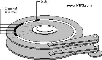
Making Tracks
On a hard disk, data is stored in thin, concentric bands. A drive head, while in one position can read or write a circular ring, or band called a track. There can be more than a thousand tracks on a 3.5-inch hard disk. Sections within each track are called sectors. A sector is the smallest physical storage unit on a disk, and is almost always 512 bytes (0.5 kB) in size.
The figure below shows a hard disk with two platters.

The structure of older hard drives (i.e. prior to Windows 95) will refer to a cylinder/ head/ sector notation. A cylinder is formed while all drive heads are in the same position on the disk. The tracks, stacked on top of each other form a cylinder. This scheme is slowly being eliminated with modern hard drives. All new disks use a translation factor to make their actual hardware layout appear continuous, as this is the way that operating systems from Windows 95 onward like to work..
To the operating system of a computer, tracks are logical rather than physical in structure, and are established when the disk is low-level formatted. Tracks are numbered, starting at 0 (the outermost edge of the disk), and going up to the highest numbered track, typically 1023, (close to the center). Similarly, there are 1,024 cylinders (numbered from 0 to 1023) on a hard disk.
The stack of platters rotate at a constant speed. The drive head, while positioned close to the center of the disk reads from a surface that is passing by more slowly than the surface at the outer edges of the disk. To compensate for this physical difference, tracks near the outside of the disk are less-densely populated with data than the tracks near the center of the disk. The result of the different data density is that the same amount of data can be read over the same period of time, from any drive head position.
The disk space is filled with data according to a standard plan. One side of one platter contains space reserved for hardware track-positioning information and is not available to the operating system. Thus, a disk assembly containing two platters has three sides available for data. Track-positioning data is written to the disk during assembly at the factory. The system disk controller reads this data to place the drive heads in the correct sector position.
4.Logical organization of hard diskA sector, being the smallest physical storage unit on the disk, is almost always 512 bytes in size because 512 is a power of 2 (2 to the power of 9). The number 2 is used because there are two states in the most basic of computer languages - on and off.
Each disk sector is labelled using the factory track-positioning data. Sector identification data is written to the area immediately before the contents of the sector and identifies the starting address of the sector.
The optimal method of storing a file on a disk is in a contiguous series, i.e. all data in a stream stored end-to-end in a single line. As many files are larger than 512 bytes, it is up to the file system to allocate sectors to store the file’s data. For example, if the file size is 800 bytes, two 512 k sectors are allocated for the file. A cluster is typically the same size as a sector. These two sectors with 800 bytes of data are called two clusters.
They are called clusters because the space is reserved for the data contents. This process protects the stored data from being over-written. Later, if data is appended to the file and its size grows to 1600 bytes, another two clusters are allocated, storing the entire file within four clusters.
Figure 3-2 Sectors and Clusters
If contiguous clusters are not available (clusters that are adjacent to each other on the disk), the second two clusters may be written elsewhere on the same disk or within the same cylinder or on a different cylinder - wherever the file system finds two sectors available. A file stored in this non-contiguous manner is considered to be fragmented. Fragmentation can slow down system performance if the file system must direct the drive heads to several different addresses to find all the data in the file you want to read. The extra time for the heads to travel to a number of addresses causes a delay before the entire file is retrieved.
Cluster size can be changed to optimize file storage. A larger cluster size reduces the potential for fragmentation, but increases the likelihood that clusters will have unused space. Using clusters larger than one sector reduces fragmentation, and reduces the amount of disk space needed to store the information about the used and unused areas on the disk.
Most disks used in personal computers today rotate at a constant angular velocity. The tracks near the outside of the disk are less densely populated with data than the tracks near the center of the disk. Thus, a fixed amount of data can be read in a constant period of time, even though the speed of the disk surface is faster on the tracks located further away from the center of the disk..
Modern disks reserve one side of one platter for track positioning information, which is written to the disk at the factory during disk assembly. It is not available to the operating system. The disk controller uses this information to fine tune the head locations when the heads move to another location on the disk. When a side contains the track position information, that side cannot be used for data. Thus, a disk assembly containing two platters has three sides that are available for data.
Hard disk interfaces
Hard disks also come in several flavors such as IDE (actually ATA), SCSI and SATA, as do optical drives. ATA is the most common interface used today. SCSI disks can usually be found on servers.
IDE
Integrated Drive Electronics, more commonly called by its acronym IDE, is an interface for hard drives. IDE is a marketing term; the real standard is called ATA.
EIDE (Enhanced IDE) or ATA-2 was later developed and increased transfer speed, added 32-bit transactions and DMA support.
ATA
ATA stands for Advanced Technology Attachment. The ATA -term is commonly used interchangeably with IDE. The older and more common paraller ATA (P-ATA) is currently being replaced by serial ATA (SATA).
Most PCs have two IDE controllers on the motherboard. One IDE controller can support two devices, so four storage devices is usually the maximum. Paraller ATA interface uses ribbon cables with 40 -pin connectors to connect the hard drives to the motherboard. The cable has usually three connectors. Of these one is connected to the motherboard and the rest two are left for hard drives. If two hard drives are connected to the same controller, one must be defined as master and the other one as slave. This is done with jumpers.
ATA-2 is the real standard for what is widely known as EIDE. ATA-2 introduced higher speed data transfer modes: PIO Modes 3 and 4 plus Multiword DMA Mode 1 and 2. These modes allow the ATA interface to run data transfers up to about 16MB/second.
SATA
Serial ATA, also known as SATA or S-ATA, is a bus used to communicate between the CPU and internal storage devices such as hard drives and optical drives. It is designed to eventually replace the ATA (also known as IDE) bus. Traditional ATA is beginning to be referred to as Parrellel ATA, P-ATA, or PATA to avoid confusion.
The main difference between SATA and PATA is in the cabling. SATA does away with the master/slave relationship of PATA (hence the difference in names), as well as PATA's ungainly ribbon cables. Instead, SATA has much slimmer and easier to manage cables, which will enable better airflow through cases. The connectors are keyed, preventing connectors from being plugged upside down. Truly native SATA drives will have different power connectors also.
A third advantage of SATA is hotplugging.
Currently, SATA has a transfer rate of 150 MB/s, which is only 17 MB/s more than standard PATA. However, with the introduction of SATA II, this is expected to go up to 300 MB/s, with 600 MB/s being released sometime around 2007. The faster bus isn't expected to affect performance in the short term, since hard drive performance is usually bottlenecked by the moving parts of the drive. During the transitional period before true native SATA drives are released, most SATA drives actually have onboard PATA controllers, which connect to SATA by a bridge. This generally causes a 30-50% performance drop. Also, PATA power connectors are still being used.
DMA
DMA (Direct Memory Access) is a function of the memory bus in the computer that lets connected devices like hard disks transfer data to the memory without the intervention of the CPU, thus speeding up the transfer. This is superior to the way PIO works.
There are two distinct types of direct memory access, DMA and bus mastering DMA. The plain DMA relies on the DMA controller on the motherboard to grab the system bus and transfer the data. In bus mastering DMA all this is done by the logic on the interface card itself. Bus mastering allows the hard disk and memory to work without relying on the old DMA controller built into the system, or needing any support from the CPU.
USB
USB (Universal Serial Bus) is a hardware bus using a serial protocol used by many different hardware devices and supported in most computers/mainboards. Originally developed by Compaq, Intel, NEC and Microsoft. It allows many devices to be connected to the bus at the same time, the theoretical maxmium is 127 devices. The maximum data transfer bandwidth is about 12Mbit/s (USB2.0 supports 480 Mbit/sec).
SCSI
SCSI - Small Computer System Interface. Pronounced "scuzzy". It's a specification for a hardware interface for connecting devices such as hard disks and scanners to a computer.
Most PCs have an ATA(IDE) bus instead of SCSI for connecting internal hard disks. SCSI is seen more often in servers, as it tends to be faster and more reliable (though more expensive). Another advantage of SCSI controller is that it requires only one IRQ and can hadle usually at least 7 devices whereas ATA can handle only 2.
Typically, you put a SCSI card in your computer, and then connect internal hard disks with a ribbon cable to some connector on the card. Also, the card will have an external connector which you might also be using simultaneously.
Fiber Channel
Fibre Channel Hard Disk Drive
The Enterprise Virtual Array supports any combination of five different Fibre Channel Hard Disk Drives (HDD) with multiple capacity points and two different rotational speeds. Three drive capacity points are supported at 36 GB, 72 GB, and 146 GB. Two rotational speeds are supported at 10,000 RPM and 15,000 RPM.
The following individual drive capacity/rotational speed combinations are available:
146GB 10,000 RPM Fibre Channel HDD
72GB 15,000 RPM Fibre Channel HDD
72GB 10,000 RPM Fibre Channel HDD
36GB 15,000 RPM Fibre Channel HDD
36GB 10,000 RPM Fibre Channel HDD
Five different Fibre Channel HDDs for the Enterprise Virtual Array provides tremendous flexibility to the target customer base by allowing mixing and matching of capacity and performance to application needs. Application areas seen as potential markets include OLTP, ERP, and any other applications requiring large amounts of online storage.
IEEE
Also called Firewire. it is a less known alternative to USB that (at its time) was better then USB for media related tasks. As of USB2 there have been significant increases, specifically more bandwidth.